
Related Manuals for Sodi Sigma KZ


Summary of Contents for Sodi Sigma KZ
- Page 1 MAN.SIG.EN.02 Configure the kart according to the guide instructions. Use spare parts of Sodi origin.
- Page 2 You have decided to acquire a SODI chassis. We would like to thank you for your trust (in us). Your kart has been developed for performance and safety. It is the outcome of SODIKART’s experience and of the latest research at the highest level of competition.
-
Page 3: Table Of Contents
5.5.2 - More braking power on the front brakes 25 9.1 - SIGMA S3........... 45 5.5.3 - More braking power on the rear brakes . 25 9.2 - SIGMA KZ ..........46 9.3 - SIGMA DD2 ..........47 MAN.SIG.EN.02 USE SPARE PARTS OF SODI ORIGIN... -
Page 4: Safety Instructions
Document MAN.SIG.CEL.FR.01 (original version), damages. which will prevail in the event of a dispute. ► The SODI chassis can only be used on The illustrations are non-contractual. an approved track and by a driver who © Sodikart 2014 . is in possession of a valid membership card of the kart’s federation of his own... -
Page 5: Recap Of All Warnings Included In This Manual
► Never drive with excessively worn pads (minimum totally, and can lead to a serious accident./ Page 40 thickness for the D18 4-piston calipers (front): 4mm)./ Page 27 MAN.SIG.EN.02 USE SPARE PARTS OF SODI ORIGIN 04/2014... -
Page 6: Reception
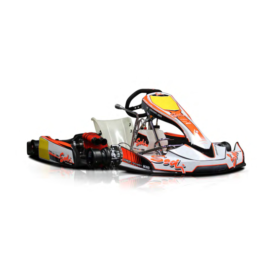
2 - Reception Legend Spoiler Nassau panel Steering column assembly Steering wheel Frame Overflow bottle Left side pod Left side pod support Right side pod 10 Right side pod support 11 Gear lever assembly (KZ only) 12 Rear bumper 13 Fuel tank 14 Seat 15 Rim ●... -
Page 7: Tooling For Assembly And Adjustment
5 T handle socket spanner 13 OU912.003 6 Piston stop centring device OU951.004 7 Master cylinder tool kit OU951.003 8 Brake bleeder OU951.002 9 Special glue LU861.001 ● (*) Supplied with the chassis. MAN.SIG.EN.02 USE SPARE PARTS OF SODI ORIGIN 04/2014... -
Page 8: Assembly
3 - Assembly Step 1 3.1 - Precautions and recommendations ● ● Do●not●overtighten●screws●and●bolts. ● Tightening torque Ø 6 = 10 to 12 mN. ● Tightening torque Ø 8 = 12 to 23 mN. ● Tightening torque Ø 10 = 23 to 47 mN. ●... -
Page 9: Adjustment
● Insert the screw into the stub axle arm. ● Place the washer between the ball joint (1) and the stub axle arm (2). ● Tighten the nut. ● Tighten the assembly. MAN.SIG.EN.02 USE SPARE PARTS OF SODI ORIGIN 04/2014... -
Page 10: Positioning Of The Safety Brake Cable
3.3 - Positioning of the safety brake cable 3.5 - Assembly of the fuel tank and of the overflow bottle Legend Safety cable Brake rod ► Always fit the safety cable clips (1) under the staples of the brake rod (2). Legend Fuel tank Steering column support... -
Page 11: Assembly Of The Seat
● C = 1050 mm ± 10 mm. SIGMA DD2 ● B = 210 mm ± 5 mm (mid-point of the rounded, middle of the seat). ● C = 1040 mm ± 10 mm. MAN.SIG.EN.02 USE SPARE PARTS OF SODI ORIGIN 04/2014... -
Page 12: Assembly Of The Seat Stiffeners
Note: It is possible to install several seat stiffener (left and right): SIGMA S3-SIGMA KZ-SIGMA DD2 : 2 stiffeners left side and 1 right side stiffener. ● For screws and nuts references, refer to the spare parts. -
Page 13: Assembly Of The Bodywork
● Drill the bushings (1) using the holes as a guide and tighten the assembly with the screws (2) and nuts (3). ● For screws and nuts references, refer to the spare parts. Step 3 MAN.SIG.EN.02 USE SPARE PARTS OF SODI ORIGIN 04/2014... - Page 14 Step 5 Step 7 Legend Spoiler Fixing plate Legend Screw Nasseau panel ● Assemble the fixing plates (2) on the spoiler (1) Lower support using screws (3). Upper support Step 6 ● Tighten the nasseau panel (1) on its supports (2) and (3) with screws, nuts, and washers.
-
Page 15: Mounting The Rear Protections
Rear protection Tubes chassis screws and nuts (9). Washer 10 Screw ● Place the rear protection (7) on the chassis tubes (8). ● Place the washers (9) and tighten using the screws (10). MAN.SIG.EN.02 USE SPARE PARTS OF SODI ORIGIN 04/2014... -
Page 16: Mounting The Front Brake Hose (Optional)
3.11 - Mounting the front brake hose (optional) Legend Brake hose Landmark drilling Screw + nut Screw + nut ● Drill the alu board to 6 mm on the landmark (2). ● Place the clamps on the brake hose (1) and tighten the screws and nuts (3). -
Page 17: Commissioning
● Under the influence of drugs and (or) alcohol. ► For your safety and the safety of other pilots, strictly follow the above instructions: not doing so may lead to severe, even fatal injuries. MAN.SIG.EN.02 USE SPARE PARTS OF SODI ORIGIN 04/2014... -
Page 18: Adjustments
4mm + 4mm SIGMA S3 SIGMA DD2 4mm + 2mm Stub axle height 4mm + 4mm + 2mm SIGMA KZ 4mm + 2mm Front tracking width A = 1 rings inside (5mm) A = 6 rings inside (30mm) B = 100mm... - Page 19 2 on the left and 2 on the right. ● These adjustments are given for information. It is advisable to refine these adjustments according to track conditions (weather - grip), driving, engine and tires. ● ● Always●attach●the●stabilisers●to●the●frame● with●a●sleeve●at●each●side. MAN.SIG.EN.02 USE SPARE PARTS OF SODI ORIGIN 04/2014...
-
Page 20: Adjustment Of Front Wheels
5.2 - Adjustment of front wheels Wet track (with front brake) 5.2.1 - Adjustment of front tracking width The adjustment of the front width is realized with several spacers (1 spacer of 15mm, and 3 spacers of 5mm for each stub axle), and 2 hubs type (short hub: 80mm or long hub: 100mm). -
Page 21: Adjustment Of The Caster
● The mark is positioned in front of the screw. (Towards the front of the chassis). Eccentrics on bottom: ● The mark is positioned on the opposite side of the screw. (Towards the rear of the chassis). MAN.SIG.EN.02 USE SPARE PARTS OF SODI ORIGIN 04/2014... -
Page 22: Adjustment Of The Camber
5.2.4 - Adjustment of the camber Standard adjustment ● See "Camber - More positive". ● ● Use●the●eccentrics●at●the●bottom. Increase the camber Description of the eccentric ● Same position as the “More negative” adjustment by replacing the lower 1° eccentric by the 2° eccentric. Reduce the camber Front ●... -
Page 23: Front Wheel Alignment
A=B with a tie rod length on the right side 1.5mm bigger than the tie rod length on the left side. ● Standard adjustment: B-1 ● Recommended in wet conditions: A-1. MAN.SIG.EN.02 USE SPARE PARTS OF SODI ORIGIN 04/2014... -
Page 24: Adjustment Of Rear Wheels
5.3 - Adjustment of rear wheels 5.3.2 - Position of rear axle 5.3.1 - Adjustment of hubs On most tracks, the correct axle position is middle position. This corresponds to a low position of the chassis relative to the ground. ●... -
Page 25: Adjustment Of Seat
► Bad maintenance of the brakes can lead to severe, even fatal injuries. ► Never repair a break system on your own; return it to your local dealer. MAN.SIG.EN.02 USE SPARE PARTS OF SODI ORIGIN 04/2014... -
Page 26: Maintenance
6 - Maintenance Brake fluid.....SUPER BLUE DOT4 Ref : LU842.010 ► The Super Blue brake fluid has been 6.1 - Brakes designed for racing use and is used exclusively for this purpose (forbidden 6.1.1 - Fluids and lubricants on open road). Brake cleaner ....... -
Page 27: Replacing Brake Pads On The D18
4-piston calipers (rear): 6 mm). ► The brake is an essential safety element. If the braking system is defective or you have the slightest doubt, do not put the kart in service. MAN.SIG.EN.02 USE SPARE PARTS OF SODI ORIGIN 04/2014... -
Page 28: Adjusting The Gap Between The Pads And The Disc
6.1.5 - Adjusting the gap between the pads and 6.1.7 - Bleeding the front brake circuit the disc Legend Adjustment screw Disc ● Tighten or loosen the screw (1) to obtain a 1 mm Legend gap between the disc (2) and the pad (3). Bleeder screw Brake pedal Reservoir... -
Page 29: An Air Bubble In The Brake System Can Lead To A Partial Or Total Lost Of Brakes And May Lead To A Serious Or Even Fatal Injury
► Use brake fluid DOT 4 only ► Test the brake after each bleed. MAN.SIG.EN.02 USE SPARE PARTS OF SODI ORIGIN 04/2014... -
Page 30: Bleeding The Rear Brake Circuit
6.1.8 - Bleeding the rear brake circuit ● ● We●recommend●that●you●drain●and●refill●the● brake●circuit●after●every●brake●pad●change.● This●will●allow●you●to●maintain●optimum● braking●performance. ● ● To●bleed●your●brake●system●more●rapidly,● especially●for●a●big●fleet,●we●recommend● the●priming●system●SODIKART●(Ref.● OU951.002). ● ● Store●the●used●brake●fluid●in●labelled● containers●until●it●is●collected●by●a●specialist● waste●disposal●company. ● ● The●brake●liquid●doesn’t●contain●petrol,●so● never●pour●the●liquid●into●a●using●oil●tank. ● ● Brake●fluid●absorbs●water●Make●sure●the● Legend replacement●brake●fluid●comes●from●a● Bleeder screw container●that●has●been●stored●in●good● conditions●and●is●recent. Reservoir ● ● Check●that●the●pedal●is●firm●after●each●... -
Page 31: Bleeding The Steering Wheel Controlled Front Brake Circuit
● Repeat the operation for the front left calliper. ● Top up the brake fluid in the reservoir (4) to its maximum level, and retighten the cap (2). MAN.SIG.EN.02 USE SPARE PARTS OF SODI ORIGIN 04/2014... -
Page 32: Replacing Rear Calliper Seals / 4 Piston Caliper Pistons D18 (Front)
6.1.10 - Replacing calliper seals / 4 piston Reassembly caliper pistons D18 (front) This operation must be performed by a Sodikart dealer. Removing Legend O-ring Piston Gasket Groove Legend ● Apply PFG110 grease to the O-rings (7). ● Check that the bases of the grooves (8) are clean. Brake pad ●... -
Page 33: Replacing Rear Calliper Seals / 4 Piston Caliper Pistons D24 (Rear)
A brake fluid screws (8). leak could appear, causing a serious or fatal accident. ● A - Bleeder screw with ball ● B - Bleeder screw without ball MAN.SIG.EN.02 USE SPARE PARTS OF SODI ORIGIN 04/2014... - Page 34 Reassembly Legend 12 Clip 13 Piston stop ● Place the piston stop clip (12) in the groove of the Legend piston stop (13). 12 Clip ● Check that the piston stop clip (12) is correctly clipped in the groove of the piston stop (13). ●...
-
Page 35: Replacing Master Cylinder Seals And Pistons
WD40 or other greasy products to clean the master cylinder. ► Do not use any cleaning product that could damage the seals. A brake fluid leak could appear, causing a serious or fatal accident. MAN.SIG.EN.02 USE SPARE PARTS OF SODI ORIGIN 04/2014... - Page 36 Reassembly Legend Yoke Piston O-ring Gasket ● Apply PFG110 grease to the O-ring (7) and the gasket (8). ● Place the O-ring (7) in the piston groove (6). ● Install the gasket (8) on the piston (6). ● Apply PFG110 grease to the O-ring (7) the gasket (8), and the piston (6).
-
Page 37: Replacing The Front Master Cylinder Pistons
● Apply PFG110 grease to the piston (5). ● Reinsert the piston (5) in the master cylinder. ● Reinstall the handle (3) and push rod (4) using the screw (1) and nut (2). ● ● Replace●any●defective●parts,●using●only● original●SODIKART●parts. MAN.SIG.EN.02 USE SPARE PARTS OF SODI ORIGIN 04/2014... -
Page 38: Tyres
6.2 - Tyres ● ● Always●change●the●whole●set●whenever●a● tyre●is●changed●(fronts,●rears,●or●all●the●set). 6.2.1 - Tyres change ● ● Always●place●the●tyres●so●that●they●rotate●in● the●direction●indicated●on●the●tyre●wall. ● ● Never●inflate●the●tyres●more●than●4●bars. ● ● Excessive●wear●of●tyres●can●be●result●from● bad●front●wheel●axle●unit●alignment. ● ● Use●tyres●with●a●grip●adapted●to●your●track. ● ● Give●worn●tyres●at●a●specialist●of●tyre● treatment●according●to●local●environmental● regulation. ► Change all damaged rims. A damaged rim may lead to a loss of tyre or loss of pressure and may lead to a serious or even fatal injury. -
Page 39: Table Of The Recommended Tyre Pressures
ROTAX MAX MOJO ROTAX DD2 MOJO NATIONALE MOJO (slick) Wet conditions: ● Little water: slightly drop the pressure from the recommended value. ● Much water: increase the pressure from the recommended value. MAN.SIG.EN.02 USE SPARE PARTS OF SODI ORIGIN 04/2014... -
Page 40: Cleaning The Chassis
6.3 - Cleaning the chassis 6.4 - Maintenance summary The cleaning of the chassis and its components is to be 6.4.1 - Bolting done with a special cleaning product (refer to the ITAKA website). Do not use the product on brake pads and Before each use, check the state of the screws and brake calipers. -
Page 41: Trouble Shooting
1. Are the tyres worn? 2. Are the tyres inflated to the recommended pressures? 3. Is the rear axle adjustment suited to the track conditions? 4. Is the front wheel axle unit adjustment correctly checked? MAN.SIG.EN.02 USE SPARE PARTS OF SODI ORIGIN 04/2014... -
Page 42: Index
8 - Index Inflation system............38 Adjustment screw ........... 27, 28, 33 Axle................24 Key for slotted round nut ..........7 Ball joint ..............8, 9 Bleeder screw ........28, 30, 31, 32, 33 Left side pod ..............6 Brake bleeder ............... 7 Left side pod support ........... - Page 43 Stub axle spacer adjuster ..........7 T handle socket spanner ..........7 T handle wrench allen key ..........7 Tire protection ............. 15 Tube protection ............15 Tyre................38 Tyre iron..............38 MAN.SIG.EN.02 USE SPARE PARTS OF SODI ORIGIN 04/2014...
- Page 44 Track: Trial: Pilot: Date: Time: TRACK CHASSIS State of the track: Stub axle height: Temperature: Caster / Camber: Parallelism: ENGINE Seat popsition: Carburator type: ● Height: ● Distance axle: Adjustments: ● Distance fork: Exhaust type: Masses: Gear ratio: Axle type: Length: Stiffeners: Chain length :...
-
Page 45: Homologation
Le marquage indiqué sur le tube transversal arriére doit rester clairement visible en permanence The marking located on the rear strut must be clearly visible at all times Copyright © 2008 by CIK-FIA. All rights reserved. Copyright © 2008 by CIK-FIA. All rights reserved. MAN.SIG.EN.02 USE SPARE PARTS OF SODI ORIGIN 04/2014... -
Page 46: Sigma Kz
9.2 - SIGMA KZ Homologation N° Homologation N° FICHE D’HOMOLOGATION 43/CH/14 43/CH/14 HOMOLOGATION FORM DESSIN TECHNIQUE DU CADRE - Échelle 1:10 TECHNICAL DRAWING OF FRAME – Scale 1:10 COMMISSION INTERNATIONALE Le dessin technique sert pour identifier la structure et la géométrie principale du cadre. (dimensions et numérotation des tubes selon tableau section B) The technical drawing is used for the identification of the structure and the main geometry of the frame. -
Page 47: Sigma Dd2
Photo of the frame from the back with the section of support for the RTPS the support for the RTPS (Rear Tire Protection System) (Rear Tire Protection System) PAGE 3 of 3 PAGE 3 of 3 MAN.SIG.EN.02 USE SPARE PARTS OF SODI ORIGIN 04/2014...
Need help?
Do you have a question about the Sigma KZ and is the answer not in the manual?
Questions and answers