
Related Manuals for Sodi ST32 BV


Summary of Contents for Sodi ST32 BV
- Page 1 USER MAINTENANCE GUIDE JANUARY 2010 This document can not be reproduced or released without the sodikart authorization. CONFIGURE THE KART ACCORDING TO THE GUIDE INSTRUCTIONS USE SPARE PARTS OF SODIKART ORIGIN...
-
Page 2: Table Of Contents
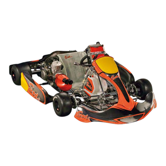
USER GUIDE ST32BV SUMMARY ST32BV SAFETY INSTRUCTIONS PREPARING THE ASSEMBLY 1- GETTING ST32BV OUT OF THE PACKING 2- TOOLS FOR ASSEMBLY 3- MAINTENANCE PRODUCTS SEQUENCE OF ASSEMBLY 4- ASSEMBLY OF THE STEERING COLUMN AND OF THE STEERING WHEEL 5- ASSEMBLY OF THE FUEL TANK AND OF THE OVERFLOW BOTTLE 6- ASSEMBLY OF THE SEAT AND OF THE SEAT STIFFENERS 10-12 7- ASSEMBLY OF THE KG BODY WORK... - Page 3 USER GUIDE ST32BV You have decided to acquire a SODI chassis. We would like to thank you for choosing the SODI ST32BV. Your kart has been developed for performance and safety. It is the outcome of SODIKART’s experience and of the latest research at the highest level of competition.
-
Page 4: Safety Instructions
The SODI chassis can only be used on an approved track and by a driver who is in possession of a valid membership card of the go-kart’s federation of his own country. -
Page 5: Getting St32Bv Out Of The Packing
USER GUIDE ST32BV 1- GETTING ST32BV OUT OF THE PACKING ST32BV FRAME SPOILER NASSEAU PANEL STEERING COLUMN ASSEMBLY STEERING WHEEL OVERFLOW BOTTLE LEFT SIDE POD RIGHT SIDE POD SUPPORT SEAT RIGHT SIDE POD FUEL TANK LEFT SIDE POD SUPPORT GEAR LEVER RIMS ASSEMBLY REAR BUMPER... -
Page 6: Maintenance Products
USER GUIDE ST32BV 2-TOOLING FOR ASSEMBLY AND ADJUSTMENT DESIGNATION DIAMETER PART NUMBER T handle wrench allen key OU 911.002 T handle wrench allen key 5 mm OU 911.003 T handle wrench allen key 6 mm OU 911.004 T handle wrench allen key 8 mm OU 911.005 T handle socket spanner... -
Page 7: Sequence Of Assembly
SEQUENCE OF ASSEMBLY AND INSTRUCTIONS STEERING COLUMN AND STEERING WHEEL (chapter 4). FUEL TANK AND OVERFLOW BOTTLE (chapter 5). SEAT AND STIFFENNERS (chapter 6). KG SODI BODYWORK (chapter 7). NOTE: RECOMMENDED TIGHTENING TORQUES: Do not overtighten screws and bolts Ø6 = 10 to 12 m.N Ø8 = 12 to 24 m.N... - Page 8 USER GUIDE ST32BV 4- ASSEMBLY OF THE STEERING COLUMN AND STEERING WHEEL. THE SET CONSISTS IN: One plastic steering column support (1). One steering wheel support (2). Two nassau panel supports (3). One steering column (4). ...
- Page 9 USER GUIDE ST32BV 4.4 TIGHTENING THE PLASTIC STEERING COLUMN SUPPORT. After completing the above steps : Tighten the screw (8). 4.5 ASSEMBLY OF THE STEERING WHEEL. STRAIGHT PART FORWARD Tighten the steering wheel (1) with the 3 screws, on the steering wheel support (2). ...
-
Page 10: Assembly Of The Fuel Tank And Of The Overflow Bottle
USER GUIDE ST32BV 5- ASSEMBLY OF THE FUEL TANK AND OF THE OVERFLOW BOTTLE. Insert the fuel tank between the steering column support (1) and the steering column (2) (see pictures ) Tighten with the fly nut (3) ... - Page 11 USER GUIDE ST32BV 6-ASSEMBLY OF THE SEAT AND SEAT STIFFENERS. Measurements given below correspond to the standard adjustment of the seat, recommended by SODIKART, for the ST32BV. 4 fixing points Get the seat supports (1) closer, or wider, depending on the seat size. Use the shims of the seat fixing kit to get a good fit.
- Page 12 USER GUIDE ST32BV 2 DISTANCE BETWEEN THE REAR AXLE AND THE MIDDLE OF THE ROUND REAR EDGE OF THE SEAT. Measure from the middle rounded edge 200 mm (7.87inch) 6-3 DISTANCE BETWEEN THE AXIS OF THE LEFT SIDE STUB AXLE FORK AND THE MIDDLE OF THE REAR ROUNDED EDGE OF THE SEAT.
- Page 13 USER GUIDE ST32BV 6-4 ASSEMBLY OF THE SEAT STIFFENERS. ASSEMBLY OF THE LOWER END (PIC 1) Put the seat stiffener lower end (1) in place. Put the bolt (2) in place and pre-tighten. For screws and bolts references, refer to the Pict.
-
Page 14: Assembly Of The Kg Body Work
USER GUIDE ST32BV 7- ASSEMBLY OF THE KG BODYWORK. ASSEMBLY OF THE SIDE POD ON ITS SUPPORTS Place the side pod (1) on the side pod support (2). Place the screws (3) through the side pod (1) and the side pod support (2). - Page 15 USER GUIDE ST32BV ASSEMBLY OF THE SPOILER Assemble the spoiler fixation kit (1) between the spoiler upper support (2) and the spoiler lower support (3) with two screws and two nuts. Place the flanges (4) between the spoiler support (2) and (3), then lock.
-
Page 16: Starting Your St32Bv
USER GUIDE ST32BV 8- STARTING YOUR ST32BV SAFETY INSTRUCTIONS TO THE PILOTS WARNING YOUR KART CAN ONLY BE DRIVEN ON A TRACK APPROVED BY CIK/FIA, OR YOUR LOCAL FEDERATION AND BY A DRIVER WHO IS IN POSSESSION OF A VALID MEMBERSHIP CARD OF THE GO-KART’S FEDERATION OF HIS OWN COUNTRY. - Page 17 USER GUIDE ST32BV 9- STANDARD ADJUSTMENTS OF THE ST32BV 4mm+4mm STUB AXLE HEIGHT 4mm +2mm 2 rings inside (10mm) 2 rings inside (20mm) FRONT TRACKING WIDTH REAR TRACKING WIDTH 1360 à 1370 1400 REAR AXLE POSITION POSITION OF MASSES Eccentrics 1° Eccentrics 4°...
- Page 18 USER GUIDE ST32BV 10- ADJUSTMENT OF FRONT WHEELS 10.1 ADJUSTMENT OF FRONT TRACKING WIDTH The adjustment of the front width is realized with several spacers (1 spacer of 15mm, and 3 spacers of 5mm for each stub axle.), and 3 hubs type (short hub: 60mm, long hub: 80mm or extra-long hub: 100mm).
- Page 19 USER GUIDE ST32BV 10.2 ADJUSTMENT OF FRONT WHEEL HEIGHT DRY TRACK Place one 4mm spacer on top and one 4 mm + one 2 mm spacer at the bottom (1). (1) DRY TRACK 4+2mm WET TRACK Place one 4 mm + one 4 mm spacers on top, and one 2 mm spacer at the bottom (2). ...
- Page 20 USER GUIDE ST32BV 10.3-ADJUSTMENT OF THE CAMBER AND OF THE CASTER DESCRIPTION OF THE ECCENTRIC. diam. 4 mm pin on the fork Marked slot 1 for 1° Eccentric ADJUSTMENT OF THE CASTER HIGH CASTER LOW CASTER FRONT FRONT FIG 2 FIG 1 RIGHT RIGHT...
- Page 21 USER GUIDE ST32BV ADJUSTMENT OF THE CAMBER USE THE ECCENTRICS AT THE BOTTOM: MORE POSITIVE MORE NEGATIVE FIG 3 FIG 4 LEFT RIGHT LEFT RIGHT Eccentrics at the bottom: Eccentrics at the bottom : The mark is positioned towards the ...
- Page 22 USER GUIDE ST32BV Lay the kart on a trolley. 2. Place the adjustment tool (1) (refer to the ITAKA catalogue). Loosen the lock nuts on each tie rod (2). Attention: on the stub axle side, lock nuts are right hand; on the steering column side, lock nuts are left hand.
- Page 23 USER GUIDE ST32BV 10.5- ADJUSTMENT OF TIE RODS ADJUSTMENT B-1 Standard adjustment. ADJUSTMENT A-1 Recommended in wet conditions. - 22 – EDITION : JANUARY 2010 MAN038.011...
- Page 24 USER GUIDE ST32BV 11- ADJUSTMENT OF REAR WHEELS 11-1 ADJUSTMENT OF HUBS Lay the kart on a trolley. AXLE 2. Remove the two wheels. 3. Measure the distance , from the basis of the hub to the axle edge. 4. Loosen the CHC (4) screws to allow the sliding of the hub on the axle.
- Page 25 USER GUIDE ST32BV 11-2 POSITION OF REAR AXLE A large ground clearance means more grip. A low ground clearance means more sliding. In most conditions, the correct axle position is the low ground clearance one. This corresponds to a high position of the axle , relative to the frame. 11-3 TYPE OF AXLE The stiffness of the axle plays an important part in the behavior of the kart.
- Page 26 USER GUIDE ST32BV AXLES DIAMETER 50 FLEXIBLE (Disadvised with the ST32 BV) MEDIUM STIFF EXTRA STIFF - 25 – EDITION : JANUARY 2010 MAN038.011...
- Page 27 USER GUIDE ST32BV 12- ADJUSTMENT OF SEAT POSITION OF THE SEAT The position of the center of gravity has also a key influence on the behavior of the kart. One can monitor this center of gravity by changing the position of the seat. You will find the best position of the seat, adapted to your size and weight, by trial-and error.
-
Page 28: Adjustment Of The Brake Distributor
USER GUIDE ST32BV 13-ADJUSTMENT OF THE BRAKE DISTRIBUTOR THE BRAKE DISTRIBUTOR ALLOW TO MONITOR THE BRACKING POWER BETWEEN THE FRONT AND REAR BRAKES. STANDARD ADJUSTMENT The brake distributor is positioned on the middle of the axle (3). This adjustment corresponds to the standard setting for the distributor of the braking power between the front and the rear brakes. -
Page 29: Tyres
USER GUIDE ST32BV 14- TYRES 14-1 CHANGING THE TYRES Lay the kart on a trolley. 2. Lay the wheel on the tire removal tool (OU942.002) 3. Once the edges of the tire are separated from the rim on both sides, remove the tire with the tool (2). - Page 30 USER GUIDE ST32BV 14-2 TABLE OF THE RECOMMENDED TYRE PRESSURES (in bar). PRESSURES SLICK TYRES COLD 20° WARM CATEGORIES BRAND TYPE FRONT REAR FRONT REAR KF1 – SLICK SOFT BRIDGE 0.55 0.55 0.75 0.75 KF1 – SLICK MEDIUM BRIDGE 0.55 0.55 0.75 0.75...
- Page 31 USER GUIDE ST32BV 15- CHANGING BRAKE PADS Unscrew piston adjustment screw to its back stop (1). Remove the 4 screws with springs (2). Remove the safety pin (3). Remove the pads; insert the new ones (4). Insert the safety pin (3).
- Page 32 USER GUIDE ST32BV 16- BLEEDING THE BRAKE SYSTEM 1- Take a petrol hose and put it on the bleed screw (3). 2- Press the brake pedal (1) and maintain the pressure. 3- Open the bleed screw (3); liquid and air bubbles come out. 4- Close the bleed screw (3).
- Page 33 USER GUIDE ST32BV 16-2 FRONT BRAKES: 1- Take a fuel hose and place it on bleeding plug (3). 2- Press the brake pedal (1) and maintain the pressure. 3- Loosen the bleeding plug (3). 4- Air and liquid go out.. 5- Tighten the bleeding plug (3).
-
Page 34: Cleaning The Chassis
USER GUIDE ST32BV 17- CLEANING THE CHASSIS The cleaning of the chassis and its components is to be done with a special cleaning product • (refer to the ITAKA catalogue). Do not use the product on brake pads and brake calipers. Avoid products which are not recommended in the ITAKA catalogue. - Page 35 USER GUIDE ST32BV 18- MAINTENANCE RECAP: Screws and bolts (general): Before each use, check the state of the screws and bolts. Pay a special attention to the ones directly linked to the safety of the kart : Stub axle screw. •...
-
Page 36: Trouble Shooting
USER GUIDE ST32BV 19- TROUBLE SHOOTING. Brakes do not work: Is the pedal working correctly (not blocked)? 2. Is the cap of the fluid reservoir tight? 3. Is the level of the brake fluid correct? 4. Are the hoses correctly connected? 5. - Page 37 TRACK: DATE: TRIAL TIMES Tyre type: Diameter: PILOT: TRIAL: TIME: TRACK: PRESSURE START State of the track: °C CHASSIS: Stub axle height : Caster and camber : Partial 1 Partial 2 Partial 3 Partial 4 Parallelism : Seat position : Height : Dist- axle : Dist- fork :...
Need help?
Do you have a question about the ST32 BV and is the answer not in the manual?
Questions and answers