
Related Manuals for SkyWave IDP 800 Series


Summary of Contents for SkyWave IDP 800 Series
- Page 1 IDP 800 Terminal Series Hardware Guide T209, Version 01 The electronic version of this document allows you to use the built-in Hyperlinks and bookmarks when using Adobe Reader © SkyWave Mobile Communications Inc. Mar 2013...
-
Page 2: Legal Notice
This documentation is provided on an as-is basis without any warranty of any kind. You assume the entire risk as to the results or performance of the software. Under no circumstance shall SkyWave be held liable for any direct, indirect, consequential, or incidental damages arising from the use or inability to use the software or documentation. -
Page 3: Table Of Contents
3.2.1 External Voltage Input ....................11 3.2.2 Power Consumption ....................... 12 3.2.2.1 Power Consumption Scenario .....................13 3.2.3 Power Off Controls ......................13 3.2.4 Power Input Options ...................... 14 3.2.5 Load Dump Circuitry ..................... 15 © SkyWave Proprietary T209, Version 01... - Page 4 4.5.1 Install the Batteries ......................43 4.5.2 Recharge the Batteries ....................45 4.5.2.1 When to Power Off the Terminal ..................47 4.5.2.2 How to Power On the Terminal ..................47 Mount the Terminal ......................47 4.6.1 Drill Mounting Holes ..................... 48 T209, Version 01 © SkyWave Proprietary...
- Page 5 APPENDIX H Cable Assembly Instructions ................. 79 Required Tools and Materials ..................... 79 Cable Assembly Steps ........................ 79 APPENDIX I IDP 800 Series to IDP 600 Series Adaptor Cable ......... 84 Revision History .......................... 87 Acronyms/Glossary ........................88 Index… ............................89 ©...
-
Page 6: List Of Figures
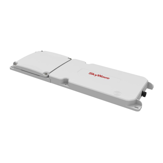
IDP 800 Terminal Series - Hardware Guide List of Figures Figure 1 IDP-800 with Battery Compartment................1 Figure 2 SkyWave's IsatData Pro Network ................2 Figure 3 Remote Standard Antenna Side Connector ..............3 Figure 4 Remote Standard Antenna Bottom Connector ............3... - Page 7 Rivet Hole Locations ....................76 Figure 57 IDP 800 Series Blunt Cut Cable ................77 Figure 58 Face View of IDP 800 Series Blunt Cut Cable Connector ........78 Figure 59 Raw Cable Details ..................... 78 Figure 60 Basic Connector Parts for Soldering Configuration ..........79 Figure 61 Recommended Stripping Length ................
- Page 8 Table 23 LED Flash Rates ......................35 Table 24 Order Part Numbers ....................63 Table 25 IDP 800 Series Mating Blunt-Cut Cable Color Code ..........78 Table 26 Cable Connector Pin-Out ..................85 T209, Version 01 viii © SkyWave Proprietary...
-
Page 9: Preface
This document is for technical readers. It provides information to ensure successful installation and operation of IDP 800 series terminals. Errata Sheet Refer to the SkyWave Customer Support website for a possible Errata Sheet available after the release of this document. Always check the site for the most current documentation releases. -
Page 10: Product Safety Datasheets
Safety Precautions The mobile device must comply with all safety precautions relating to the operation, usage, service and repair of the terminal. SkyWave assumes no liability for the customer’s failure to comply with any of these precautions. Caution warnings appear throughout this document. -
Page 11: Installation Warning
SkyWave’s directors, officers, employees, agents and assigns and for such purposes SkyWave is or shall be deemed to be acting as agent or trustee on behalf of and for the benefit of such companies and persons Limited Liability SkyWave’s liability is limited to the cost of repair or replacement of any of SkyWave’s... -
Page 12: Warranty
This warranty is limited to the repair and/or replacement of any defective components experienced under normal specified operating use and storage conditions, at SkyWave’s discretion. It does not cover any damages caused or associated with the product’s misuse. The end-user’s only remedy or recourse is against the Solution Provider, and any experience with defective products should be communicated to your Solution Provider. -
Page 13: Product Overview
IDP 800 Terminal Series - Hardware Guide 1 Product Overview The IDP 800 series low profile terminal contains an integrated antenna, an application card, a satellite modem for communicating with the satellite, a panel connector for optimal external power input, RS-232, three (3) configurable input/output ports and; a serviceable battery compartment. -
Page 14: Terminals
Internet-based application services provided by SPs or by integrating existing customer enterprise software to receive information from the Gateway. 1.2 Terminals The IDP 800 series of SkyWave mobile satellite terminals operate on the IsatData Pro network. Terminals include an omni-directional (integrated or remote) antenna, satellite modem, GPS, programmable microcontroller, a side connector and three I/O (input/output) feeds capable of monitoring and controlling external sensors and devices. -
Page 15: Remote Antennas
IDP 800 Terminal Series - Hardware Guide 1.3 Remote Antennas The IDP 800 series supports two optional remote satellite antenna models: the standard antenna with an elevation angle of 20 to 90° and the low elevation antenna from -15 to 90°. -
Page 16: Terminal Key Features And Benefits
1.4 Terminal Key Features and Benefits CAUTION Do not rely solely on the terminal for emergency (SOS) calls. The IDP 800 series terminals have the following key features and benefits: External power input Motion detection/accelerometer Magnetically activated power on/off switch ... -
Page 17: Operating Modes
1.6.2 Satellite Modem For the most part, the satellite modem operates independently of the application controller. Consequently, power consumed by the satellite modem must be added separately to determine a terminal's overall power consumption. © SkyWave Proprietary T209, Version 01... -
Page 18: Gps
LED On/Off The LED can be enabled by the software. I/O Active/Inactive The I/O can be configured as an input or output. Power consumption consumed by the I/O is defined in section 3.2.2. T209, Version 01 © SkyWave Proprietary... -
Page 19: Charge Operating Modes
The terminal is operating from external power. It never charges a (not charging) non-rechargeable battery. Rechargeable batteries are not charged if the battery is topped up or the battery temperature is out of range. © SkyWave Proprietary T209, Version 01... - Page 20 IDP 800 Terminal Series - Hardware Guide THIS PAGE INTENTIONALLY LEFT BLANK T209, Version 01 © SkyWave Proprietary...
-
Page 21: Compliance
IEC 60950-22:2005 (1st Edition) - Safety IEC 60950-1:2005 (2nd Edition); Am 1:2009 CAUTION This certification is void if batteries other than those specified in Section 3.8.1 are used. IEC 62311 - Radiation safety © SkyWave Proprietary T209, Version 01... - Page 22 European Union's (EU) Directive 2002/95/EEC "Restriction of Hazardous Substances" (RoHS) in Electronic and Electrical Equipment. European directive OJ L 78, 26.3.1991, p. 38. Directive as amended by Commission Directive 98/101/EC (OJ L 1, 5.1.1999, p. 1). T209, Version 01 © SkyWave Proprietary...
-
Page 23: Specifications
Storage Temperature -40° to +85°C excluding batteries 3.1.2 Battery Temperature SkyWave has tested and certified the IDP-800 based on the batteries. The table below defines the battery's temperature specifications from the manufacturer's datasheet. Rechargeable Batteries Non-rechargeable Batteries Battery Chemistry... -
Page 24: Power Consumption
If the terminal is in Power Off mode, then all peripherals are off and the current draw is zero (0). Table 6 Power Off Values Power Off Current Power Off 11.6 µA (battery power) 17 µA (external power) T209, Version 01 © SkyWave Proprietary... -
Page 25: Power Consumption Scenario
IDP 800 Terminal Series - Hardware Guide 3.2.2.1 Power Consumption Scenario Power consumed by the IDP-800 is a fairly involved. SkyWave has provided a Power Estimator on the support site to help customer estimate power and battery life for their particular applications. -
Page 26: Power Input Options
Table 8 defines the IDP-800's operating mode as a function of the external voltage and internal voltage. As external and input voltages changes, the terminal has an automatic switchover that does not affect the terminal's operation. T209, Version 01 © SkyWave Proprietary... -
Page 27: Load Dump Circuitry
3.3V to 6.3 V. Terminal starts to transmit. This is when the antenna's power amplifier is turned The maximum in-rush specifications @ 12 V DC are shown in Table 9. PowerOffThreshold is defined in section 3.2 © SkyWave Proprietary T209, Version 01... -
Page 28: Reverse Polarity
RS-232 Tx I/O 01 I/O 02 I/O 03 3.2.10 Input/Output The terminal's three (3) configurable I/O lines each operate independently in one of following modes: Digital input with weak (1 MΩ) pull down T209, Version 01 © SkyWave Proprietary... - Page 29 Each of the configurable I/O lines can generate an interrupt in order to wake up the processor from the Power Save mode. To generate the interrupt, the interrupt line should be configured and enabled. © SkyWave Proprietary T209, Version 01...
-
Page 30: Input/Output Specifications
Typical input impedance Nominal input range Resolution (12 bits) Proportional measurement error INL error Ignition Sense Mode Input current (for Vin > 4 V) µA kΩ Typical input impedance (for Vin < 4 V) T209, Version 01 © SkyWave Proprietary... -
Page 31: Rf Connector
The IDP-800 is optionally available to support a remote antenna. The remote antenna terminal variant uses an SMA panel connector. The terminal must only be used with an active SkyWave antenna. Refer to APPENDIX A for antenna order part numbers. -
Page 32: Serial Interfaces
Serial Rx Input High Threshold (Vcc 3.3 V) Serial Tx Low Output -3.7 (loaded with 3 k to ground) Serial Tx High Output (loaded with 3 k to ground) ESD Performance RS-232 pins (Tx, Rx) ±15 T209, Version 01 © SkyWave Proprietary... -
Page 33: Rf Specifications
Remote Standard Antenna Parameter Value Maximum EIRP 7.0 dBW Elevation angle 20 degrees 3.6.4 Remote Low Elevation Antenna Parameter Value Maximum EIRP 5.0 dBW Elevation angle -15 degrees Maximum transmit antenna gain 2.5 dBic © SkyWave Proprietary T209, Version 01... -
Page 34: Gps
Warm Start Hot Start Sensitivity Tracking -159 dBm Hot Start -156 dBm Cold Start -147 dBm Accuracy Horizontal Position (CEP) 2.5 m Velocity 0.1 m/s Heading 0.5 degrees CEP, 50%, 24 hours static, -130 dBm T209, Version 01 © SkyWave Proprietary... -
Page 35: Internal Battery
IDP 800 Terminal Series - Hardware Guide 3.8 Internal Battery 3.8.1 Battery Type SkyWave has tested and certified the terminal with the batteries listed in Table 18. The specifications in Table 18 have been extracted from the manufacturer's specifications. CAUTION Use only SkyWave approved batteries listed below. -
Page 36: Battery Type Identification
IDP-800 and battery covers for the non-rechargeable (red dots) and rechargeable (green dots) terminals. The color dots on the lid and in the battery compartment must match. Figure 12 Non-Rechargeable Terminal Red dots on battery cover and battery compartment T209, Version 01 © SkyWave Proprietary... -
Page 37: Charger
3.8.4 Charger The IDP-800 internal charger only supports rechargeable NiMH battery chemistries. Only use approved SkyWave NiMH batteries in the IDP-800. The IDP-800 charger operates independently of the Lua framework. Consequently, charging can occur in any operating mode. The charging algorithm is outlined in Figure 14 and described in detail later in this section. -
Page 38: Charger Stages Initiation
The internal battery cannot be continuously charged. However, it is important to ensure that the internal battery has a maximum charge when external power is disconnected. Charging is initiated in the following cases providing the temperature range is valid. External Power applied. T209, Version 01 © SkyWave Proprietary... -
Page 39: Temperature Monitoring
Fast-charge current is second charging stage. The charger enters this stage once the battery voltage is over 12 V. The charger remains in the fast-charge stage for 4 hours or until the dV/dT threshold is exceeded. © SkyWave Proprietary T209, Version 01... -
Page 40: Accelerometer
The IDP-800 has an internal 3D accelerometer to detect motion in any axis. Figure 15 shows the positive axes for the accelerometer. As the battery compartment temperature is to measure temperature, the maximum temperature is reduced from the safety recommendation provided by the battery manufacturer. T209, Version 01 © SkyWave Proprietary... -
Page 41: Figure 15 Accelerometer Axis
Accelerometer Specification Parameter Condition Units Resolution 3.91 Acceleration software selectable ±2 Range software selectable ±4 software selectable ±8 software selectable ±16 Bandwidth Selectable via digital interface 1000 Filtering Sensitivity LSB/g LSB/g LSB/g 16 g LSB/g © SkyWave Proprietary T209, Version 01... -
Page 42: Non-Volatile Storage
The IDP-800 has 8MB compared to 4MB on IDP-600 series terminal. It is strongly recommended that applications restrict usage to 4MB memory as the additional 4MB should be reserved for future Lua framework features. T209, Version 01 © SkyWave Proprietary... -
Page 43: Mechanical
13.6.2 after a dust and sand bombardment test as detailed in IEC 60529, section 13.4. Drop Test The terminal meets all its specifications after a handling drop test as specified in SAE J1455, section 4.11.3.1. 3.12 Mechanical All dimensions are shown in millimeters. © SkyWave Proprietary T209, Version 01... -
Page 44: Terminal
Value Mass Transceiver without batteries (excludes mounting bracket) ~0.94 kg Transceiver with rechargeable batteries (excludes mounting bracket) ~1.27 kg Transceiver with non-rechargeable batteries (excludes mounting bracket) ~1.14 kg Enclosure Material Lexan EXL 9330 Resin T209, Version 01 © SkyWave Proprietary... -
Page 45: Remote Antenna
2 x 72.4 4 x 5.500 (HOLE) 126.2±0.2 2 x 112.8 35.5±0.2 46.5±0.2 4 x 15.9 Note: Centre antenna cable hole is for bottom connector antenna only. Figure 20 Remote Standard Antenna Height Dimensions 25±0.3 © SkyWave Proprietary T209, Version 01... -
Page 46: Figure 21 Remote Low Elevation Antenna Height Dimensions (Mm)
Figure 21 Remote Low Elevation Antenna Height Dimensions (mm) 76±0.3 Parameter Value Mass Remote Standard Antenna 360 g (Side entry with 5 m cable) Remote Low Elevation Antenna 365 g (Side entry with 5 m cable) Enclosure Material Xenoy 5220U T209, Version 01 © SkyWave Proprietary... -
Page 47: Led
5 seconds seconds Already Powered On Entering Fast 50 milli- 250 milli- 5 seconds Power Off seconds seconds The LED can be optionally controlled by the Lua Framework. Refer to [T204] for further details. © SkyWave Proprietary T209, Version 01... - Page 48 IDP 800 Terminal Series - Hardware Guide THIS PAGE INTENTIONALLY LEFT BLANK T209, Version 01 © SkyWave Proprietary...
-
Page 49: Installation
IDP 800 Terminal Series - Hardware Guide 4 Installation The following section contains SkyWave's recommended installation guidelines for the Solution Provider (SP). These recommendations should be incorporated into installation guidelines for end users. CAUTION The installer is responsible for following all safety guidelines during product installation. -
Page 50: Mobile Identification
4.2.2 Mobile Identification Each mobile device has a unique mobile ID used by SkyWave to register it on the IsatData Pro network. This is a 15-digit alphanumeric identifier in the format NNNNNNNNSKYXXXX. The mobile ID is located both on the bottom of the terminal, and on the battery end, as well as on the shipping box. -
Page 51: Figure 24 Manage Mobile Devices
Keep a copy (APPENDIX E) of the terminal's mobile ID along with the server access ID and password you receive in the activation report email (Figure 25) from SkyWave Customer Support. You need these to communicate remotely with the terminal. -
Page 52: Required Materials
Qty 6 - M4 (8-32) nuts with 18-8 stainless steel flat and lock washers Waterproof sealing tape Qty 1 - Custom cable SkyWave recommends that the Solution Provider supply the end-user with a custom built cable. 4.2.5 Required Tools You require the following tools to install a terminal. -
Page 53: Remote Antenna Mounting Guidelines (Optional)
20 cm away from humans. CAUTION Cable management and connector strain relief must be incorporated in the installation. SkyWave highly recommends securing the cable at regular intervals along its length as part of © SkyWave Proprietary T209, Version 01... -
Page 54: Identify The Fuse Panel Location (Optional)
If you ordered a terminal with rechargeable batteries the label on the underside of the terminal shows NiMH, while the non-rechargeable battery label shows Li/FeS label inside the battery compartment also identifies the cell chemistry. T209, Version 01 © SkyWave Proprietary... -
Page 55: Install The Batteries
4. Insert the batteries paying close attention to battery orientation (Figure 28). If your terminal has not been factory set to automatically power on, then use the magnet fob to power on the terminal. © SkyWave Proprietary T209, Version 01... -
Page 56: Figure 28 Battery Orientation (Non-Rechargeable Shown)
APPENDIX A for part number. Figure 29 Gasket and Gasket Wall Ensure the gasket is securely attached to the gasket wall 6. Position the battery cover onto the battery compartment, lining-up the straight edges (Figure 30). T209, Version 01 © SkyWave Proprietary... -
Page 57: Recharge The Batteries
Rechargeable batteries should be fully charged (4 hours) prior to initial use. The batteries can be recharged by connecting either an external power cable (ST100165) or an IDP 800 AC power adapter cable (ST100164). © SkyWave Proprietary T209, Version 01... -
Page 58: Figure 32 Led, Target, And Connector Cap
Do not use a wrench. A tactile click is felt when the collar is properly engaged. 3. Plug the AC power adapter into a wall outlet. 4. Charge the batteries for at least 4 hours. T209, Version 01 © SkyWave Proprietary... -
Page 59: When To Power Off The Terminal
Magnet Fob Magnet Sensor 4.6 Mount the Terminal The IDP 800 series terminals can be installed with or without mounting brackets (APPENDIX A). Users can also build their own custom bracket (Section 4.6.2). CAUTION Painting terminals or antennas may interfere with their performance. -
Page 60: Drill Mounting Holes
M4 (8-32) screws and torque to 1.4 N-m (12 in-lb). 4. Continue with the steps, below, for Apply Dielectric Grease. 4.6.2 Custom Bracket Guidelines SkyWave recommends customers follow the guidelines below if building their own custom bracket. All hardware must be 18-8 stainless steel. -
Page 61: Mount The Remote Antenna (Optional)
4. Apply waterproof sealing compound, such as RTV silicone, around the drill holes so water does not seep into the asset. CAUTION Adhesive or silicone cannot block the air vent features shown in Figure 35. Figure 35 Air Vent Feature Do Not Block These Features © SkyWave Proprietary T209, Version 01... -
Page 62: Adhesive Mount
Failure to follow the manufacturer's guidelines could result in the remote antenna separating from the mounting surface. CAUTION Adhesive or silicone cannot block the air vent features shown in Figure 36. Figure 36 Air Vent Feature Do Not Block These Features T209, Version 01 © SkyWave Proprietary... -
Page 63: Silicone Side Connector Mount
The two vertical slots shown in Figure 37 are vent features and must not be filled with silicone. Figure 37 Apply Silicone to Remote Antenna Do Not Block These Features 8. Place some weight on the remote antenna while the silicone cures. © SkyWave Proprietary T209, Version 01... -
Page 64: Silicone Bottom Connector Mount
SMA cable connector. For a right angle SMA cable connector, drill a minimum hold diameter of 29 mm. Refer to the note in step 7 if the right angle hole is considered too large. T209, Version 01 © SkyWave Proprietary... -
Page 65: Figure 39 Drill Mounting Hole
Torque the connector finger tight plus a 45 degree rotation using an 8 mm wrench. Figure 40 Attach Cable to Terminal 5. Apply silicone around the hole in the asset and to the bottom surface of the remote antenna. © SkyWave Proprietary T209, Version 01... -
Page 66: Figure 41 Apply Silicone To Hole In Asset
Also note that the silicone used to mount the antenna must be fully cured before the cable can be installed from the inside otherwise the seal and mounting are compromised. T209, Version 01 © SkyWave Proprietary... -
Page 67: Route The Main Cable (Optional)
Ensure the power cable will not be pinched, kinked or worn down by any objects or moving parts such as the door hinges. It is very important to secure the cable at many points along its path. © SkyWave Proprietary T209, Version 01... -
Page 68: Figure 44 Sample Cable Placement In A Vehicle Cab
Where possible route the cable through existing holes in the floor or the firewall of the engine compartment. 3. Route the cable starting from the terminal to the fuse panel or battery source. Note: SkyWave recommends that you tape cable ends to prevent dirt from collecting on the contacts. T209, Version 01... -
Page 69: Apply Dielectric Grease
Do not use a wrench. A tactile click is felt when the collar is properly engaged. Figure 46 Cable Connector and Locking Collar 6. Wipe off any extra lubricant around the connector. © SkyWave Proprietary T209, Version 01... -
Page 70: Protect The Cables And Cable Connectors
Protect the Cables and Cable Connectors CAUTION Cable management and connector strain relief must be incorporated in the installation. SkyWave highly recommends securing the cable at regular intervals along its length as part of the installation to prevent cable wear and eliminate strain on the terminal connector. -
Page 71: Register The Terminal
Note: The IDP 800 series terminals must complete registration to operate. Once you apply power, the terminal goes into satellite search mode to acquire the SkyWave IsatData Pro network. This activity may take a few minutes to complete. If you experience difficulties, refer to Section 5 for troubleshooting suggestions. -
Page 72: Cleaning Instructions
Note: The terminal will not register until it has a clear line of sight to the satellite. 2. The SkyWave IsatData Pro network records the registration message and forwards the registration message to the user’s application. The SkyWave IsatData Pro network sends an acknowledgement message over the satellite to the terminal. -
Page 73: Troubleshooting The Terminal
Replace the device, if the above checks fail to uncover the problem. 5.2 Shipping Terminals Back to SkyWave If it is necessary to ship the terminal back to SkyWave, follow the SkyWave RMA process. Note: Remove all batteries from the terminal prior to returning the terminal. Do not return the batteries with the shipment as doing so may complicate the shipping documentation and labeling requirements. - Page 74 IDP 800 Terminal Series - Hardware Guide THIS PAGE INTENTIONALLY LEFT BLANK T209, Version 01 © SkyWave Proprietary...
-
Page 75: Appendix A Order Part Numbers
VHB Rail Bracket ST100187 Mating Connector with Solder Cup Kit ST100137 Contact your Account Executive for additional products and ordering codes. Some antennas come in various cable lengths. Contact your Account Executive for additional details. © SkyWave Proprietary T209, Version 01... -
Page 76: Appendix B Activation Information
IDP 800 Terminal Series - Hardware Guide Activation Information APPENDIX B Server User Name: ________________________________________________________ Password: _______________________________________________________________ Terminal Type/ Description Location Mobile ID (NNNNNNNNSKYXXXX) T209, Version 01 © SkyWave Proprietary... -
Page 77: Appendix C Replacing Lithium Batteries
48), avoiding the location shown in Figure 49. A flat screwdriver inserted into the slots on the vertical sides and end face of the terminal may assist cover removal. Figure 48 Battery Cover - Sides © SkyWave Proprietary T209, Version 01... -
Page 78: Figure 49 Battery Cover - Areas To Avoid
6. Replace the gasket (SkyWave part number: ST100188). Refer to APPENDIX E for gasket replacement instructions. 7. Position the loaded battery cover onto the terminal, with the curved end of the cover facing the end of the terminal. -
Page 79: Appendix D Reinstalling Or Replacing A Terminal
3 seconds and then remove. The LED emits a few short flashes. Refer to [T204] for LED operation information and flash rates. © SkyWave Proprietary T209, Version 01... -
Page 80: Appendix E Replacing A Battery Gasket
CAUTION Damaged gaskets must be replaced. (SkyWave part number: ST100188) The black battery compartment gasket is accessible with the battery cover removed. The gasket is secured by hook features on the outside of the gasket wall and matching loop features on the gasket (Figure 50). -
Page 81: Figure 51 Fit Loops Over The Hooks
IDP 800 Terminal Series - Hardware Guide Figure 51 Fit Loops over the Hooks CAUTION Ensure that the black gasket on the terminal remains fully in place on the gasket wall along the entire perimeter of the battery compartment. © SkyWave Proprietary T209, Version 01... -
Page 82: Appendix Fvhb Rail Bracket Installation
2. Attach the lanyard to the center stud, matching the location shown in Figure 52, and following the order below: Flat washer Lanyard (not required if using the rivet option below) Split washer Hex nut T209, Version 01 © SkyWave Proprietary... -
Page 83: Figure 52 Vhb Rail Bracket And Lanyard
Figure 53 Lanyard Attached to Terminal 4. Secure the terminal in place by assembling the flat washer, split washer, and hex nut to the remaining five studs. 5. Torque the hex nuts to 1.4 N-m (12 in-lb). © SkyWave Proprietary T209, Version 01... -
Page 84: Figure 54 Assembled Terminal With Vhb Rail Bracket And Lanyard
55) back from the vehicle nose. In most cases it is best to locate the terminal on the surface between two roof bows. The lanyard dictates the distance from the driver's side edge of the vehicle, approximately 15 cm. Note: Do not remove the VHB tape protective backing in this step. T209, Version 01 © SkyWave Proprietary... -
Page 85: Select A Mount Option
You require the following tools and materials for the installation. These items do not ship with the kit. Clean shop cloths 50\50 mixture of isopropyl alcohol and water 3M rubber and vinyl spray adhesive 80 © SkyWave Proprietary T209, Version 01... - Page 86 VHB on the bracket and the mounting surface. This is especially important if the mounting surface is plastic or painted metal. 3. Wait a few minutes until the mounting location is dry. T209, Version 01 © SkyWave Proprietary...
- Page 87 24 hours at 15°C. Higher temperatures will shorten the cure time - minimum cure time is 30 minutes at 65°C. 8. Drill through the hole provided at each end of the brackets (four places) with a 4.9 mm drill bit (Figure 56). © SkyWave Proprietary T209, Version 01...
-
Page 88: Figure 56 Rivet Hole Locations
~1.27 kg Transceiver with non-rechargeable batteries (excludes mounting bracket) ~1.14 kg Magnet mount bracket (brackets, magnets and fasteners) ~0.50 kg VHB mount bracket (brackets and fasteners) ~0.42 kg Enclosure Material Lexan EXL 9330 Resin T209, Version 01 © SkyWave Proprietary... -
Page 89: Appendix G Idp 800 Series Blunt Cut Cable
I/O lines, and one each for ground and input voltage. The cable has an over-molded connector, a floating drain wire that is terminated to ground. Figure 57 IDP 800 Series Blunt Cut Cable Specifications Parameter... -
Page 90: Figure 58 Face View Of Idp 800 Series Blunt Cut Cable Connector
IDP 800 Terminal Series - Hardware Guide Figure 58 Face View of IDP 800 Series Blunt Cut Cable Connector Table 25 IDP 800 Series Mating Blunt-Cut Cable Color Code Position Color Wire Gauge Functionality Black 22 AWG Ground Yellow 24 AWG... -
Page 91: Appendix H Cable Assembly Instructions
(Figure 61) and remove any foil shielding. CAUTION Be careful not to nick the wire insulation. For cables exposed to extreme temperatures and sun, select a cable with a thermal rating of -40°C to +85°C and a UV resistant jacket. © SkyWave Proprietary T209, Version 01... -
Page 92: Figure 61 Recommended Stripping Length
5. Push the red O-ring inside the back side of the back shell (Figure 63). Figure 63 O-ring 6. Verify the red gasket is present and oriented with the flat face visible in the front side of the back shell as shown in Figure 64. T209, Version 01 © SkyWave Proprietary... -
Page 93: Figure 64 Red Gasket
8. Ensure the O-ring is in place over the connector body as shown in Figure 66. Figure 66 O-Ring over Connector Body 9. Use silicone sealant to completely fill the end of the connector and the area between the wires (Figure 67). © SkyWave Proprietary T209, Version 01... -
Page 94: Figure 67 Silicone In The Connector
Figure 69 Cable Exit Area 13. Assemble the sealing nut over the back shell until the cable grip makes full contact with the perimeter of the cable jacket (Figure 70). Wipe away any excess sealant. T209, Version 01 © SkyWave Proprietary... -
Page 95: Figure 70 Assembled Sealing Nut
IDP 800 Terminal Series - Hardware Guide Figure 70 Assembled Sealing Nut © SkyWave Proprietary T209, Version 01... -
Page 96: Appendix Iidp 800 Series To Idp 600 Series Adaptor Cable
IDP 800 Series to IDP 600 Series Adaptor Cable APPENDIX I This cable (ST100143-001) allows an IDP 800 series terminal to be installed in place of an IDP 600 series terminal. The cable has seven connections. The RS-485 connections on the IDP 600 series terminal are left unconnected. -
Page 97: Figure 72 Idp 800 Series Mating Connector End Pin-Out
IDP 800 Terminal Series - Hardware Guide Figure 72 IDP 800 Series Mating Connector End Pin-Out Figure 73 IDP 600 Series Connector End Pin-Out Key Feature Table 26 Cable Connector Pin-Out IDP 800 Position IDP 600 Position Wire Gauge 22 AWG... - Page 98 IDP 800 Terminal Series - Hardware Guide THIS PAGE INTENTIONALLY LEFT BLANK T209, Version 01 © SkyWave Proprietary...
-
Page 99: Revision History
Revision History Version Date Details Mar 2013 Official customer release 0.22 Mar 2013 Limited customer release 0.18 Dec 2012 Limited customer release 0.12, 0.14, Nov 2012 Limited customer release 0.15 Oct 2012 Limited customer release © SkyWave Proprietary T209, Version 01... -
Page 100: Acronyms/Glossary
Electrostatic Discharge Federal Communications Commission ground Global Positioning System input/output International Electrotechnical Commission kilogram-force centimeter kgf·cm light-emitting diode radio frequency Restriction of Hazardous Substances RoHS Radio and Telecommunications Terminal Equipment R&TTE receive Solution Provider transmit T209, Version 01 © SkyWave Proprietary... -
Page 101: Index
IsatData Pro network connectors ..........16 description ..........1 dimensions ..........32 features ............ 1 features............ 4 maximum messages from-mobile.... 1 user serviceable parts ........ xii maximum messages to-mobile ....1 warranty ............ xii key slot © SkyWave Proprietary T209, Version 01... - Page 102 www.SkyWave.com...
Need help?
Do you have a question about the IDP 800 Series and is the answer not in the manual?
Questions and answers