
Related Manuals for SkyWave IDP-782


Summary of Contents for SkyWave IDP-782
- Page 1 IDP-782 Hardware Guide T213, Version 02 The electronic version of this document allows you to use the built-in hyperlinks and bookmarks when using Adobe Reader © SkyWave Mobile Communications Inc. Jun 2015...
-
Page 2: Legal Notice
This documentation is provided on an as-is basis without any warranty of any kind. You assume the entire risk as to the results or performance of the software. Under no circumstance shall SkyWave be held liable for any direct, indirect, consequential, or incidental damages arising from the use or inability to use the software or documentation. -
Page 3: Table Of Contents
IDP-782 - Hardware Guide TABLE OF CONTENTS Legal Notice Contact Information TABLE OF CONTENTS List of Figures List of Tables Preface What's New? Purpose Audience Errata Sheet Notation Reference Safety Disclaimer Safety Precautions Installation Warning Installer Responsibility Limited Liability Warranty... - Page 4 3.2.2.1 Accelerometer Power Consumption 3.2.3 Load Dump Protection 3.2.4 Inrush Currents 3.2.5 Cellular Antenna 3.2.6 SIM Holders 3.3 Connectors 3.3.1 IDP-782 Connector Pin Assignment 3.4 Input/output Interface Specifications 3.4.1 Digital Input 3.4.2 Digital Output 3.4.2.1 Push-pull 3.4.2.2 Open Drain 3.4.3 Analog Input 3.4.4 Open Drain Outputs...
- Page 5 3.8.4 Headset Speaker 3.9 Backup Battery 3.10 Memory 3.11 Environmental 3.12 Sensors 3.12.1 Temperature Sensor 3.12.2 Accelerometer 3.13 IDP-782 GPRS - Cellular Module 3.14 IDP-782 HSPA - Cellular Module 3.15 Mechanical 3.15.1 Transceiver 3.15.2 Cellular Antenna 3.15.3 Satellite Antenna 3.15.3.1 Standard Antenna 3.15.3.2 Low Elevation Antenna...
- Page 6 IDP-782 - Hardware Guide 4.3.3 Determine Terminal Orientation for Accelerometer Use 4.4 Mount the Antennas 4.4.1 Screw Mount 4.4.2 Adhesive Mount 4.4.2.1 Silicone Side Connector Mount 4.4.2.2 Silicone Bottom Connector Mount 4.4.3 Cellular Antenna 4.5 Route the Main Cable 4.5.1 Protect the Cables and Cable Connectors 4.6 Connect to Power...
-
Page 7: List Of Figures
IDP-782 - Hardware Guide List of Figures Figure 1: IDP-782 Figure 2: System Architecture Figure 3: Connector Positioning Figure 4: Dual SIM Access Door Figure 5: LEDs Figure 6: Cellular Antenna Figure 7: Standard Satellite Antenna Figure 8: Low Elevation Satellite Antenna... - Page 8 IDP-782 - Hardware Guide Figure 30: Accelerometer and Terminal Orientation Figure 31: Apply Silicone to Antenna Figure 32: Weight on the Antenna Figure 33: Drill Mounting Hole Figure 34: Attach Cable to Terminal Figure 35: Apply Silicone to Hole in Asset...
- Page 9 IDP-782 - Hardware Guide Figure 60: Locking Clip (removed) and Plastic Housing Figure 61: Transceiver Electrical Mating Connector Pins (front view) Figure 62: Mating Connector Electrical Cable (front view) Figure 63: Mating Cable T213, Version 02 © SkyWave Proprietary...
-
Page 10: List Of Tables
IDP-782 - Hardware Guide List of Tables Table 1: Terminal with Backup Battery Temperature Specifications Table 2: Terminal Input Currents Table 3: Additional Terminal Input Currents Table 4: Electrical Pin Assignment Table 5: Hardware GPS and Dual GPS/GLONASS Specifications Table 6: Internal Backup Battery... -
Page 11: Preface
IDP-782 satellite-cellular terminal. Errata Sheet Refer to the SkyWave Customer Support website for updates or for an Errata Sheet that might be available after the release of this document. Always check the website for the most current documentation. -
Page 12: Safety Disclaimer
SkyWave recommends that this product be installed by the authorized distributor from whom it has been purchased. By carrying out the installation of the product, the installer assumes exclusive responsibility for, and agrees to indemnify SkyWave from, any injury or damage of any kind arising from the installation. T213, Version 02... -
Page 13: Installer Responsibility
SkyWave’s directors, officers, employees, agents and assigns and for such purposes SkyWave is or shall be deemed to be acting as agent or trustee on behalf of and for the benefit of such companies and persons. -
Page 14: Warranty
A fault report is required for each unit returned under warranty. Please contact SkyWave’s Customer Support for additional information. User Serviceable Parts The IDP-782 contains two SIM card holders and may also have SIM cards installed (not supplied by SkyWave). Battery Safety Warnings Do not short circuit or expose the battery to temperatures above the maximum rated temperature. -
Page 15: Product Overview
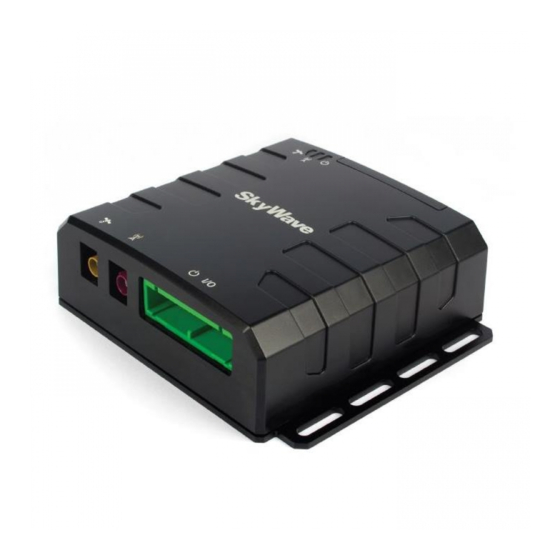
IDP-782 - Hardware Guide 1 Product Overview The IDP-782 (Figure 1) is a high-performance satellite-cellular communication terminal consisting of: A transceiver unit An IsatData Pro satellite modem for communicating with the satellite An integral GPS/GLONASS subsystem I/O interface for wired sensors and devices... -
Page 16: Overview Of The Messaging System
Default acknowledged messages Global service Service is provided to end users by Solution Providers (SPs) who use the SkyWave IsatData Pro network to offer particular applications and/or services to their clients. The SPs link their application services to the satellite terminals by connecting to the IsatData Pro gateway. This acts as the communications hub of the system, routing traffic to and from the terminals and the various service providers. -
Page 17: Terminal
Terminals are suitable for the AVL market. Feature-rich software tools make application design easy, and shorten the design and testing time. SkyWave also provides consulting services to SPs to help program the terminals and get customer applications running quickly. -
Page 18: Transceiver Unit
I/Os (input/output) capable of monitoring and controlling external sensors and devices. Ideal for mobile applications, it is also suitable for fixed installations. A variant of the IDP-782 is available with a rechargeable backup battery. Refer to APPENDIX A for details. -
Page 19: Figure 3: Connector Positioning
IDP-782 - Hardware Guide Figure 3: Connector Positioning An anti-tamper SIM door on the back side of the unit (Figure 4) provides easy access to the two SIM card holders. A mini-B USB connector located next to the SIM door provides a serial port for programming and debugging. -
Page 20: Cellular Antenna
IDP-782 - Hardware Guide Figure 5: LEDs 1.3.2 Cellular Antenna Terminals use a quad-band adhesive glass mount antenna, designed for installation on the interior of a vehicle windshield. It connects to the transceiver unit with a 2.5 m cable terminated with a violet colored FAKRA connector. -
Page 21: Figure 7: Standard Satellite Antenna
IDP-782 - Hardware Guide The IDP-782 is available with either the standard satellite antenna (Figure 7) or the low elevation satellite antenna (Figure 8). Figure 7: Standard Satellite Antenna Figure 8: Low Elevation Satellite Antenna T213, Version 02 © SkyWave Proprietary... -
Page 22: Compliance
IDP-782 - Hardware Guide 2 Compliance Unless noted otherwise, the information below refers to terminals without backup battery. Inmarsat Type Approval Industry Canada ICES-003 RSS-170, Issue 2, Spectrum Management and Telecommunications Policy, Radio Standard (IDP- 180/IDP190) RSS-102,radiation safety per Safety Code 6 (compliance shown by computation) - Page 23 IDP-782 - Hardware Guide UN 38.3 Transportation Compliance PTCRB Compliant for terminals without backup battery Compliance for terminals with backup battery is pending T213, Version 02 © SkyWave Proprietary...
-
Page 24: Specifications
IDP-782 - Hardware Guide 3 Specifications 3.1 Temperature Parameter Value -40° to +85°C Operating Temperature -40° to +85°C excluding batteries Storage Temperature excluding batteries -40° to +85°C Reverse Polarity Protection -40 V maximum 3.1.1 Backup Battery Temperature Table 1 defines the backup battery's temperature specifications. -
Page 25: Table 2: Terminal Input Currents
IDP-782 GPRS - Tx 850 MHz band; burst current peak 392.3 mA 50 MHz band; average current 112.9 mA IDP-782 HSPA - 2G Tx 850 MHz band; GPRS; burst current 557.7 mA peak 850 MHz band; GPRS; average current OFF 153.5 mA... -
Page 26: Accelerometer Power Consumption
IDP-782 - Hardware Guide Table 3: Additional Terminal Input Currents Mode of Operation Port Condition Current Sleep mode Main serial port (cable connected) 0.070 mA AUX serial port (trace enabled and cable connected) 0.033 mA USB main port 37.9 mA... -
Page 27: Sim Holders
For detailed instructions on the connector contact crimp, assembly and extraction, refer to the manufacturer’s website . APPENDIX F provides mating cable assembly instructions and mating connector, crimp, and tool part numbers. 3.3.1 IDP-782 Connector Pin Assignment Table 4 maps to the layout shown in Figure 9. http://www.te.com/commerce/DocumentDelivery/DDEController , document ID/document number: 411-5761, document title: 040II SERIES MULTI-LOCK CONNECTOR MK-II 72POS. -
Page 28: Input/Output Interface Specifications
IDP-782 - Hardware Guide Figure 9: Transceiver View of Connector Table 4: Electrical Pin Assignment AUX_ AUX_ Output Output MIC_B SPK_B CAN_L RS485 RS485 SPK_ RS232 RS232 I/O 04 I/O 03 I/O 02 I/O 01 Main_ Main_ MIC_A CAN_H 1_WIRE... -
Page 29: Digital Input
IDP-782 - Hardware Guide I/O 04 provides dedicated overcurrent/short circuit protection circuitry when operated in the open drain, switch-to-ground mode. The other I/Os do not have this circuitry therefore I/O 04 is recommended for applications requiring overcurrent/short circuit protection. Simplified block diagrams of the I/O when configured as digital inputs, digital outputs, and analog inputs are shown in the figures below (Figure 10, Figure 11, and Figure 12). -
Page 30: Digital Output
IDP-782 - Hardware Guide Parameter Min. Typical Max. Units Input low range 1.05 Input high range 1.95 Input current with weak pull-down µA (weak 1 MΩ pull-down still in place); = 3.0 V Input source current with pull-up µA = 0.0 V) Input sink current with pull-down µA... -
Page 31: Push-Pull
IDP-782 - Hardware Guide 3.4.2.1 Push-pull In the push-pull configuration the output is driven directly from the microprocessor. Parameter Min. Typical Max. Units Output high voltage - open circuit 2.65 3.15 2.85 3.15 Output high voltage (sourcing 25 µA) 2.50 2.80... -
Page 32: Open Drain Outputs
IDP-782 - Hardware Guide Figure 12: Analog Input Parameter Min. Typical Max. Units Input impedance MΩ Minimum measurement voltage Maximum measurement voltage 2.75 Normal input range Resolution (12 bits) Proportional measurement error INL error Absolute limits 3.4.4 Open Drain Outputs The terminal provides two open drain outputs (output05 and output06) that can be used to turn on various devices such as relays, lights or audible alarms. -
Page 33: Pass-Through Mode
IDP-782 - Hardware Guide Figure 13: Open Drain Outputs Parameter Typical Max. Units Sink Current Applied Voltage Voltage output (sink current = 250 mA) 0.34 3.4.5 Pass-Through Mode A terminal can be configured for pass-through mode when there is no application firmware present. A block diagram of pass-through mode is shown in Figure 14. -
Page 34: Serial Interfaces
IDP-782 - Hardware Guide Figure 14: Pass-Through Mode Signals The terminal's I/O lines are configured as per Figure 14 when in pass-through mode. The modem's serial data and the EVENT_NOTIFICATION pins are connected to the terminal's external connector. 3.5 Serial Interfaces... -
Page 35: Rs-485
IDP-782 - Hardware Guide Interrupting service for receive, transmit. Receive and transmit message queue management. The terminal incorporates a controller area network interface with signaling rates up to 1 Mbps. Note: You must provide a termination resistor externally to the terminal. -
Page 36: Rs-232
IDP-782 - Hardware Guide 3.5.3 RS-232 The RS-232 interface defaults to the following settings: 9600 bit/s, 1 start, 8 data, 1 stop bit, and no parity. The baud rate is configurable up to 115,200 bps. The electrical characteristics of the interface are: Parameter Min. -
Page 37: Usb
IDP-782 - Hardware Guide 3.5.5 USB The terminal incorporates a USB to 4 port UART bridge chip. Both RS-232 serial ports can be switched through the bridge to the USB port. The USB port is accessible via a Mini-B connector on the rear of the terminal. -
Page 38: Audio
IDP-782 - Hardware Guide Table 5: Hardware GPS and Dual GPS/GLONASS Specifications Parameter GLONASS Time to First Fix 1 Cold Start Warm Start Hot Start Sensitivity Tracking -162 dBm -158 dBm Hot Start -156 dBm -156 dBm Cold Start -148 dBm... -
Page 39: Hspa Audio
IDP-782 - Hardware Guide Parameter Min. Typical Max. Units Speaker Differential output voltage Common mode output voltage 1.25 Output current limit Output load resistance Ω Signal to noise (16 Ω load, input signal = 0 dBFS) Signal to noise (32 Ω load, input signal = 0 dBFS) 3.8.2 HSPA Audio... -
Page 40: Headset Speaker
IDP-782 - Hardware Guide 3.8.4 Headset Speaker Parameter Min. Typical Max. Units Speaker Impedance (1 kHz) Ω Power Handling Capacity Operating Frequency 20000 3.9 Backup Battery Terminals with backup batteries are shipped in shelf mode with the backup battery disabled. External power must be applied to exit shelf mode and begin charging the battery to its maximum capacity. -
Page 41: Memory
IDP-782 - Hardware Guide 3.10 Memory Parameter Value SRAM 8 Mb Flash 16 Mb 3.11 Environmental Parameter Description Vibration The terminal meets all its specifications during exposure to random vehicular vibration levels per SAE J1455, section 4.9.4.2 figures 6, 7, and 8, and MIL-STD-810G, section 514.6, figure 514.6C-1. -
Page 42: Sensors
IDP-782 - Hardware Guide 3.12 Sensors 3.12.1 Temperature Sensor Parameter Value Range -40 to +85°C Accuracy ±2°C (-25 to +85°C) ±3°C (below -25°C) 3.12.2 Accelerometer The terminal has a 3D accelerometer to detect motion in any axis. In low power applications frequent GPS fixes can dominate the power budget. To reduce the power budget effects of GPS fixes, the accelerometer can be used to detect if motion has occurred. -
Page 43: Idp-782 Gprs - Cellular Module
IDP-782 - Hardware Guide 3.13 IDP-782 GPRS - Cellular Module Type u-blox SARA-G3 series (SARA-G350) GPRS Module GSM 850/900/1800/1900 MHz Output Power Class 4: 33 dBm for EGSM850/900 Class 1: 30 dBm for GSM 1800/1900 Input Power Peak current of 1.5 A typical. -
Page 44: Mechanical
IDP-782 - Hardware Guide Output Power GPRS Class 4: 33 dBm for GSM/E-GSM bands Class 1: 30 dBm for DCS/PCS bands Edge Class E2 (27 dBm) for GSM/E-GSM bands Class E2 (26 dBm) for DCS/PCS bands HSPA Class 3 (24 dBm) for WCDMA/HSDPA/HSUPA mode Input Power Peak currents of 1.8 A typical, 2 A maximum. -
Page 45: Cellular Antenna
IDP-782 - Hardware Guide 3.15.2 Cellular Antenna Parameter Value Mass 80 g including cable Dimensions 116.0 x 21.5 x 4.3 mm (LxWxH) Cable length 2.5 m Mounting Adhesive backing 3.15.3 Satellite Antenna Figure 15: Satellite Antenna (standard and low elevation) - Bottom View (mm) T213, Version 02 ©... -
Page 46: Standard Antenna
IDP-782 - Hardware Guide 3.15.3.1 Standard Antenna Parameter Value Mass Side entry with 5 m cable: 360 g Enclosure Material Lexan EXL 9330 Color Code 8T9D076 (white) ® Sealing Gasket Material Santoprene Figure 16: Standard Antenna Height Dimensions (mm) 3.15.3.2 Low Elevation Antenna... -
Page 47: Figure 17: Low Elevation Antenna Height Dimensions (Mm)
IDP-782 - Hardware Guide Figure 17: Low Elevation Antenna Height Dimensions (mm) T213, Version 02 © SkyWave Proprietary... -
Page 48: Installation
IDP-782 - Hardware Guide 4 Installation The following section contains recommended installation guidelines for the Solution Provider (SP). These recommendations should be incorporated into installation guidelines for end users. The installer is responsible for following all safety guidelines during product installation. -
Page 49: Required Tools
#1 and #2 Philips screwdriver 4.2.4 Mobile Identification Each terminal has a unique mobile ID used by SkyWave to register it on the IsatData Pro network. This is a 15-digit alphanumeric identifier in the format NNNNNNNNSKYXXXX. The mobile ID is located on the bottom of the terminal and on the shipping box. -
Page 50: Figure 19: Remove Sim Card Door
IDP-782 - Hardware Guide SIM card, activated for use with a cellular network, from a Service Provider serving the area the terminal operates in. The SIM card must support operation on 1.8 V or 3 V. The terminal does not support 5 V SIM cards. -
Page 51: Led Location And Operation
IDP-782 - Hardware Guide Figure 21: Sample SIM Card Orientation 5. Push gently until the card is all the way in (Figure 22). Use the main SIM card holder slot (Figure 23) if using only a single SIM card. Figure 22: SIM Card Installed Figure 23: SIM Card Holders 6. -
Page 52: Figure 24: Led Location
IDP-782 - Hardware Guide Figure 24: LED Location Terminal Power - Red Indicates that the terminal has external power. This LED is on continuously (solid red) when power is applied. Satellite Status - Yellow Indicate satellite communications status as follows: Figure 25 and Figure 26 show the power on LED flashing sequence. -
Page 53: Led User Control
IDP-782 - Hardware Guide When the LED is under the control of the LSF, the flashing patterns shown in Table 7 are used to indicate the current state of the modem. Table 7: Modem State LED Flashing Patterns Modem Flashing Pattern... -
Page 54: Activate The Terminal
4.2.6 Activate the Terminal To send or receive any message you must activate the terminal on the IsatData Pro network. 1. Log in to https://support.skywave.com, type your user name (registered email) and password, and then click GO. Contact SkyWave Customer Support at support@skywave.com... -
Page 55: Determine A Suitable Mounting Location
IDP-782 - Hardware Guide Figure 28: Sample Activation Report 4.3 Determine a Suitable Mounting Location Before installing the terminal, consider the important guidelines provided below. Most users install the terminals in a vehicle. It is very important for installers to install the terminals in a safe and secure way to avoid danger or damage to persons or property. -
Page 56: Standard Antenna Mounting Guidelines
This information is used later to setup the accelerometer service. Example 1: If the transceiver is mounted horizontally under the vehicle dash such that the white SkyWave logo is facing down and the cables are exiting towards the driver, then record “Top facing down and connectors facing back”. -
Page 57: Cellular Antenna Mounting Guidelines
IDP-782 - Hardware Guide Figure 29: Antenna Cable Bend Radius Mount on a surface that is free from dirt, grime, water and grease to avoid damaging the mounting surface or the vehicle’s paint. Mount so that the cable end faces the rear of the vehicle. -
Page 58: Mount The Antennas
IDP-782 - Hardware Guide Figure 30: Accelerometer and Terminal Orientation 4.4 Mount the Antennas Two mounting options are available for the satellite antenna: screw mount or silicone mount. 4.4.1 Screw Mount If mounting an antenna the following tools and materials are required:... -
Page 59: Adhesive Mount
IDP-782 - Hardware Guide Cable management and connector strain relief must be incorporated in the installation. Secure the cable no more than 15 cm from the antenna enclosure and at regular intervals along its length as part of the installation to prevent cable wear and eliminate strain on the terminal connector. -
Page 60: Silicone Bottom Connector Mount
IDP-782 - Hardware Guide Figure 31: Apply Silicone to Antenna 4. Place some weight on the antenna while the silicone cures. Figure 32: Weight on the Antenna Cable management and connector strain relief must be incorporated in the installation. Secure the cable no more than 15 cm from the antenna enclosure and at regular intervals along its length as part of the installation to prevent cable wear and eliminate strain on the terminal connector. -
Page 61: Figure 33: Drill Mounting Hole
IDP-782 - Hardware Guide 1. Find a location for the antenna following the guidelines provided in Section 4.3.1. 2. Drill a 12 to 19 mm hole in the asset surface (Figure 33) when using a straight SMA cable connector. For a right angle SMA cable connector, refer to step 7. -
Page 62: Figure 35: Apply Silicone To Hole In Asset
IDP-782 - Hardware Guide Figure 35: Apply Silicone to Hole in Asset 6. Lower the antenna onto the mounting surface. The straight SMA cable connector can be lowered straight down onto the mounting surface. The right angle SMA cable connector, not shown, must be pivoted down onto the mounting surface to fit the right angle cable and connector through a larger clearance hole. -
Page 63: Cellular Antenna
IDP-782 - Hardware Guide 8. Place some weight on the antenna while the silicone cures. Figure 37: Weight on the Antenna Cable management and connector strain relief must be incorporated in the installation. Secure the cable no more than 15 cm from the antenna enclosure and at regular intervals along its length as part of the installation to prevent cable wear and eliminate strain on the terminal connector. -
Page 64: Route The Main Cable
4.5.1 Protect the Cables and Cable Connectors Cable management and connector strain relief must be incorporated in the installation. SkyWave highly recommends securing the cable at regular intervals along its length as part of the installation to prevent cable wear and eliminate strain on the connector. -
Page 65: Connect To Power
Section 2 Compliance. The installer is responsible for complying with local electrical codes. Note: SkyWave recommends that if possible you wait until the terminal is unblocked (has a full view of the sky) before powering on the terminal. -
Page 66: Can Bus Connection
To connect the terminal CAN bus serial interface to the CAN bus of the vehicle, SkyWave recommends an induction sensor, which allows the terminals' CAN bus interface to read information from the CAN bus without damaging the vehicle wires. -
Page 67: Figure 41: Connect The Satellite Antenna
IDP-782 - Hardware Guide Figure 41: Connect the Satellite Antenna 2. Connect the cellular antenna (Figure 42) to the violet colored FAKRA connector on the terminal by pushing until you hear a click. Figure 42: Connect the Cellular Antenna 3. Connect the power and I/O cable to the terminal by pushing until you hear a click. -
Page 68: Figure 43: Connect The I/O Power Cable
IDP-782 - Hardware Guide Figure 43: Connect the I/O Power Cable 4. Mount the terminal using cable ties, or washers and screws. You can use cable ties as long as the terminal remains flat and is either parallel or perpendicular to the ground, for proper operation of the internal accelerometer. -
Page 69: Terminals With A Terminal Shroud
IDP-782 - Hardware Guide 4.7.2 Terminals with a Terminal Shroud In order for the transceiver to be IP65 compliant, the terminal shroud must be assembled as per the following instructions. If you are not using a terminal shroud, continue to section 4.8 1. -
Page 70: Figure 47: Rf Cable Through The Terminal Shroud Opening
5. Cut the smallest hole possible to pass the green I/O connector through the I/O cable portion of the terminal shroud. Note: If the other end of the cable is smaller than the green I/O connector, SkyWave recommends passing the smaller end through the hole from inside to outside to limit the size of the hole required. -
Page 71: Figure 49: Connect The Connectors To The Terminal
IDP-782 - Hardware Guide Figure 49: Connect the Connectors to the Terminal 8. Insert the terminal in the terminal shroud as shown in Figure 50. Ensure the shroud sits properly over the terminal. Figure 50: Terminal in Shroud 9. Apply outdoor grade silicone, for maximum protection, around the perimeter of the terminal shroud opening, over the small reset hole, and around any mounting hardware (Figure 51). -
Page 72: Figure 51: Apply Silicone
IDP-782 - Hardware Guide Figure 51: Apply Silicone Figure 52: Reset Button 10. Inject outdoor grade silicone inside the cable openings of the terminal shroud and massage the terminal shroud to remove any bubbles. 11. Attach a cable tie around each opening and tighten around the cables (Figure 53). -
Page 73: Figure 53: Cable Ties And Silicone
IDP-782 - Hardware Guide Figure 53: Cable Ties and Silicone 13. If mounting the terminal with mounting hardware, pierce holes in the terminal shroud using the mounting slot indicators on the shroud (Figure 54). Figure 54: Mounting Slot Indicators 14. If mounting the terminal with cable ties, or washers and screws, insert the mounting hardware through the pierced holes and then mount the terminal. -
Page 74: Disconnect The Fakra Connector
Note: The terminals must complete registration to operate. When you apply power, the terminal goes into satellite search mode to acquire the SkyWave IsatData Pro network. This activity may take a few minutes to complete. If you experience difficulties, refer to Section 5 for troubleshooting suggestions. -
Page 75: Cleaning Instructions
IDP-782 - Hardware Guide 4.10 Cleaning Instructions The transceiver and cellular antenna are for indoor use, and under normal circumstance should not require any cleaning. However, if cleaning is required, wipe with a damp cloth using a mild detergent. Do not immerse in water, and ensure that water does not enter through the connector openings. -
Page 76: Troubleshooting The Terminal
Verify with your SP that the terminal is assigned to your account and registered (that it is sending and receiving) and that the SkyWave IsatData Pro network is operating properly. Check the condition of the power cable. The IDP-782 features a red power LED to indicate power is available. -
Page 77: Appendix A Order Part Numbers
5 m antenna cable for bottom connector antenna (above) ST301044-AFC 5 m right angle antenna cable for bottom connector antenna (above) ST301044-ARC Accessories Terminal development cable ST100320-001 Refer to the SkyWave Catalog for additional accessories or contact your SkyWave Account Manager. T213, Version 02 © SkyWave Proprietary... -
Page 78: Appendix B Activation Information
IDP-782 - Hardware Guide APPENDIX B Activation Information Server User Name: ________________________________________________________ Password: _______________________________________________________________ Terminal / Mobile ID IMEI Number/ ICCID Location Description (NNNNNNNNSKYXXXX) Number T213, Version 02 © SkyWave Proprietary... -
Page 79: Appendix C Satellite Antenna Dimensions
IDP-782 - Hardware Guide APPENDIX C Satellite Antenna Dimensions Before drilling check the template against actual hardware for dimensional accuracy. If it is not correct, DO NOT USE THIS TEMPLATE. Use the physical antenna hardware as a template. Cable management and connector strain relief must be incorporated in the installation. -
Page 80: Appendix D Terminal Shroud
IDP-782 - Hardware Guide APPENDIX D Terminal Shroud The optional terminal shroud protects the cable connectors that connect to the transceiver unit. The terminal shroud has two (2) pass through features for the following cables: RF cables Power and I/O cables... -
Page 81: Appendix E Remove The Fakra Housing For Cable Installation (Optional)
IDP-782 - Hardware Guide APPENDIX E Remove the FAKRA Housing for Cable Installation (optional) To remove the FAKRA housing, so it can fit through a small hole, follow the steps below. 1. Remove the locking clip (Figure 58) from the plastic housing using a small pair of electronics pliers. -
Page 82: Appendix F Mating Cable Assembly Instructions
IDP-782 - Hardware Guide APPENDIX F Mating Cable Assembly Instructions The following section provides the information required to assemble a terminal power/interface cable. Protect the connector pins during assembly and installation. Mating Connector and Terminal Pins Part Numbers The mating connector and crimp contact part numbers are shown in Table 9. -
Page 83: Cable Selection
It is important to do field testing with RF environments before finalizing the cable design. Tools Wire Cutter Wire Stripper Crimping Tool Fine-tip Soldering Iron Solder For production cable assembly, SkyWave recommends the crimping and extraction tools listed in Table 10. T213, Version 02 © SkyWave Proprietary... -
Page 84: Table 10: Crimping And Extraction Tools
Cable management and connector strain relief must be incorporated in the installation. SkyWave highly recommends securing the cable at regular intervals along its length as part of the installation to prevent cable wear and eliminate strain on the terminal connector. Damage to the terminal connector interface or cable might result leading to hardware failure. -
Page 85: Acronyms/Glossary
IDP-782 - Hardware Guide Acronyms/Glossary Controller Area Networks COFETEL Comisión Federal de Telecomunicaciones (Federal Telecommunications Commission of Mexico) direct current EGSM Enhanced GSM Electrostatic Discharge encapsulating security payload Federal Communications Commission ground GPRS General Packet Radio Service Global Positioning System... - Page 86 IDP-782 - Hardware Guide R&TTE Radio and Telecommunications Terminal Equipment receive Satellite Earth Stations and Systems Subscriber Identification module Solution Provider SRAM Static Read and Write Memory transmit Universal Serial Bus Vbatt Power supply voltage T213, Version 02 © SkyWave Proprietary...
-
Page 87: Revision History
IDP-782 - Hardware Guide Revision History Version Date Details 1.02 May 2015 Limited Customer Release Jan 2015 Official Customer Release Jan 2015 Limited Customer Release Nov 2014 Limited Customer Release Identificação ANATEL Representante no Brasil Orbcomm do Brasil Telecomunicações Ltda Fone: 51 9515 3417 email: laggazio.hercules@orbcomm.com...
Need help?
Do you have a question about the IDP-782 and is the answer not in the manual?
Questions and answers