Sign In
Upload
Manuals
Brands
SkyWave Manuals
Touch terminals
IDP 800 Series
SkyWave IDP 800 Series Manuals
Manuals and User Guides for SkyWave IDP 800 Series. We have
1
SkyWave IDP 800 Series manual available for free PDF download: Hardware Manual
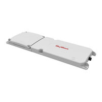
SkyWave IDP 800 Series Hardware Manual (102 pages)
Brand:
SkyWave
| Category:
Touch terminals
| Size: 2 MB
Table of Contents
Legal Notice
2
Table of Contents
3
Contact Information
2
List of Figures
6
Preface
9
Purpose
9
Audience
9
Errata Sheet
9
Notation
9
Reference
9
Battery Safety Warnings
9
Product Safety Datasheets
10
Safety Disclaimer
10
Safety Precautions
10
Installation Warning
11
Installer Responsibility
11
Limited Liability
11
Warranty
12
User Serviceable Parts
12
1 Product Overview
13
Overview of the Messaging System
13
Figure 1 IDP-800 with Battery Compartment
13
Terminals
14
Figure 2 Skywave's Isatdata Pro Network
14
Remote Antennas
15
Figure 3 Remote Standard Antenna Side Connector
15
Figure 4 Remote Standard Antenna Bottom Connector
15
Figure 5 Remote Low Elevation Antenna Side Connector
15
Terminal Key Features and Benefits
16
Pass-Through Mode
16
Operating Modes
17
Application Controller
17
Satellite Modem
17
Figure 6 Pass-Through Mode
17
Table 1 Application Controller Operating Modes
17
Gps
18
Application Peripherals
18
Table 2 Satellite Modem Operating Modes
18
Table 3 Application Peripherals
18
Charge Operating Modes
19
Table 4 Charge Operating Modes
19
2 Compliance
21
3 Specifications
23
Temperature
23
Terminal Temperature
23
Battery Temperature
23
Electrical
23
External Voltage Input
23
Power Consumption
24
Table 5 Operational Power Consumption Values
24
Table 6 Power off Values
24
Power Consumption Scenario
25
Power off Controls
25
Table 7 Power Consumption Scenario
25
Power Input Options
26
Figure 7 Magnet Fob on the Magnet Sensor
26
Load Dump Circuitry
27
Fuse
27
In-Rush Current
27
Table 8 Power Input Options
27
Reverse Polarity
28
Power Connector
28
Connector Pin-Out
28
Input/Output
28
Figure 8 Mating Terminal Connector Pin Assignment
28
Table 10 Reverse Polarity
28
Table 11 Terminal Connector
28
Table 12 Terminal Electrical Pin Assignment
28
Table 9 In-Rush Current Specifications @ 12 V
28
Input/Output Specifications
30
RF Connector
31
Antenna Cut Detection
31
Pass-Through Mode
31
Figure 9 Pass-Through Mode Signals
31
Table 13 RF Connector
31
Table 14 Pass-Through Mode Power
31
Serial Interfaces
32
Table 15 Pass-Through Mode Timing Specifications
32
Table 16 Pass-Through Mode Power Consumption
32
RF Specifications
33
Frequency
33
Terminal with Integrated Antenna
33
Remote Standard Antenna
33
Remote Low Elevation Antenna
33
Gps
34
Table 17 GPS Specifications
34
Internal Battery
35
Battery Type
35
Table 18 Approved Skywave Batteries
35
Battery Type Identification
36
Battery Lid Matching
36
Figure 10 Rechargeable (Nimh) Battery Label
36
Figure 11 Non-Rechargeable
36
Figure 12 Non-Rechargeable Terminal
36
Charger
37
Figure 13 Rechargeable Terminal
37
Charger Stages Initiation
38
Figure 14 Charging Flowchart
38
Temperature Monitoring
39
Charging Stages
39
Table 19 Charger Initiation Parameters
39
Table 20 Battery Temperature Specifications
39
Accelerometer
40
Table 21 Charging Stage Specifications
40
Figure 15 Accelerometer Axis
41
Table 22 Accelerometer Specification
41
Non-Volatile Storage
42
Environmental
42
Mechanical
43
Terminal
44
Figure 16 IDP-800 Top View Enclosure Dimensions
44
Figure 17 IDP-800 Side View Enclosure Dimensions
44
Figure 18 IDP-800 Connector View Enclosure Dimensions
44
Remote Antenna
45
Figure 19 Remote Standard and Low Elevation Antenna - Bottom View (MM)
45
Figure 20 Remote Standard Antenna Height Dimensions
45
Figure 21 Remote Low Elevation Antenna Height Dimensions (MM)
46
Led
47
Table 23 LED Flash Rates
47
4 Installation
49
Getting Started
49
Prepare for the Installation
49
Shipping Box Contents
49
Mobile Identification
50
Activate the Terminal
50
Figure 22 Mobile ID Location
50
Figure 23 Remote Antenna Serial Number Label Location (Standard Antenna Shown)
50
Figure 24 Manage Mobile Devices
51
Figure 25 Sample Activation Report
51
Required Materials
52
Required Tools
52
Determine a Suitable Mounting Location
52
Remote Antenna Mounting Guidelines (Optional)
53
Identify the Fuse Panel Location (Optional)
54
Prepare the Batteries
54
Figure 26 Remote Antenna Cable Bend Radius
54
Figure 27 Battery Cover Screws
55
Install the Batteries
55
Figure 28 Battery Orientation (Non-Rechargeable Shown)
56
Figure 29 Gasket and Gasket Wall
56
Figure 30 Battery Cover
57
Figure 31 Apply Pressure Around the Battery Cover
57
Recharge the Batteries
57
Figure 32 LED, Target, and Connector Cap
58
Figure 33 Locking Collar and Key Slot
58
How to Power on the Terminal
59
When to Power off the Terminal
59
Mount the Terminal
59
Figure 34 Magnet Fob
59
Custom Bracket Guidelines
60
Drill Mounting Holes
60
Mount the Remote Antenna (Optional)
61
Screw Mount
61
Figure 35 Air Vent Feature
61
Adhesive Mount
62
Figure 36 Air Vent Feature
62
Figure 37 Apply Silicone to Remote Antenna
63
Silicone Side Connector Mount
63
Figure 38 Weight on the Antenna
64
Silicone Bottom Connector Mount
64
Figure 39 Drill Mounting Hole
65
Figure 40 Attach Cable to Terminal
65
Figure 41 Apply Silicone to Hole in Asset
66
Route the Main Cable (Optional)
67
Figure 42 Apply Silicone to Terminal
67
Figure 43 Weight on the Antenna
67
Figure 44 Sample Cable Placement in a Vehicle Cab
68
Apply Dielectric Grease
69
Figure 45 Apply Silicone Lubricant to Connector
69
Figure 46 Cable Connector and Locking Collar
69
Protect the Cables and Cable Connectors
70
Apply Power
70
Power on the Battery Terminal
70
Connect to External Power (Optional)
70
Figure 47 Cable Management
70
Register the Terminal
71
Cleaning Instructions
72
5 Troubleshooting the Terminal
73
Terminal Does Not Register or Report
73
Shipping Terminals Back to Skywave
73
APPENDIX A Order Part Numbers
75
Table 24 Order Part Numbers
75
APPENDIX B Activation Information
76
APPENDIX C Replacing Lithium Batteries
77
Figure 48 Battery Cover - Sides
77
Figure 49 Battery Cover - Areas to Avoid
78
APPENDIX D Reinstalling or Replacing a Terminal
79
APPENDIX E Replacing a Battery Gasket
80
Figure 50 Gasket Hook and Loop Features
80
Figure 51 Fit Loops over the Hooks
81
APPENDIX Fvhb Rail Bracket Installation
82
Installation Guidelines
82
Attach the Bracket and Prepare the Surface
82
Figure 52 VHB Rail Bracket and Lanyard
83
Figure 53 Lanyard Attached to Terminal
83
Figure 54 Assembled Terminal with VHB Rail Bracket and Lanyard
84
Select a Mount Option
85
Figure 55 Installation Location for VHB Rail Bracket and Lanyard
85
Figure 56 Rivet Hole Locations
88
APPENDIX G IDP 800 Series Blunt Cut Cable
89
Figure 57 IDP 800 Series Blunt Cut Cable
89
Figure 58 Face View of IDP 800 Series Blunt Cut Cable Connector
90
Figure 59 Raw Cable Details
90
Table 25 IDP 800 Series Mating Blunt-Cut Cable Color Code
90
APPENDIX H Cable Assembly Instructions
91
Required Tools and Materials
91
Cable Assembly Steps
91
Figure 60 Basic Connector Parts for Soldering Configuration
91
Figure 61 Recommended Stripping Length
92
Figure 62 Cable with Sealing Nut and a Back Shell
92
Figure 63 O-Ring
92
Figure 64 Red Gasket
93
Figure 65 Wires and Solder Cups
93
Figure 66 O-Ring over Connector Body
93
Figure 67 Silicone in the Connector
94
Figure 68 Silicone in the Grommet
94
Figure 69 Cable Exit Area
94
Figure 70 Assembled Sealing Nut
95
APPENDIX Iidp 800 Series to IDP 600 Series Adaptor Cable
96
Figure 71 IDP 800 Series to IDP 600 Series Adaptor Cable
96
Figure 72 IDP 800 Series Mating Connector End Pin-Out
97
Figure 73 IDP 600 Series Connector End Pin-Out
97
Table 26 Cable Connector Pin-Out
97
Revision History
99
Acronyms/Glossary
100
Index
101
Advertisement
Advertisement
Related Products
SkyWave IDP-680
SkyWave IDP-690
SkyWave IDP-782
SkyWave IDP 700 Series
SkyWave IDP 100 Series
SkyWave ORBCOMM IDP-280
SkyWave ORBCOMM IDP-290
SkyWave Categories
Touch terminals
Modem
Conference System
Transceiver
More SkyWave Manuals
Login
Sign In
OR
Sign in with Facebook
Sign in with Google
Upload manual
Upload from disk
Upload from URL