
Related Manuals for Grant Spira Series


Summary of Contents for Grant Spira Series
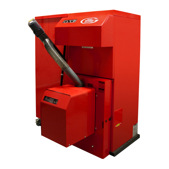
- Page 1 Grant Spira 5-18kW, 6-26kW and 9-36kW Condensing Wood Pellet Boiler User, Installation and Servicing Instructions UK | DOC 0042 | Rev 2.0 | October 2015...
- Page 2 All good sold are subject to our official Conditions of Sale, a copy of which may be obtained on application. © Grant Engineering (UK) Limited 2015. No part of this manual may be reproduced by any means without prior written consent.
-
Page 3: Table Of Contents
User Instructions - contents For the Installation and Servicing Instructions, please refer to page 20. Introduction About your Boiler General Pellet Hoppers Bulk Pellet Stores Boiler Operation Cleaning About your Fuel Boiler Controls Boiler Control Panel Burner Control Panel Burner Control Panel Error Messages Service Indicator Active Symbols... -
Page 4: Introduction
If you have a bulk pellet store you will have either a bulk store auger, or a Grant SpiraVAC vacuum system, to move the pellets from the bulk store to the pellet hopper as and when required. Check with your installer regarding which system you have fitted. If you have the Grant SpiraVAC system, please refer to the instructions provided with that system for details of its operation. -
Page 5: Boiler Operation
(if fitted) will need to be re-primed before the pellet hopper is automatically filled from the bulk store. If a Grant SpiraVAC vacuum system is fitted refer to the Instructions supplied with the system to restart the pellet supply to the pellet hopper. - Page 6 Meets EN Plus Grade A1. Correct diameter and length with no dust and minimum bark content. Figure 3-1: Correct grade of pellets Pellets not pressed correctly causing them to easily disintegrate. DO NOT USE! The auger will be unable to consistently deliver these pellets from the hopper to the burner, resulting in pellet lighting problems.
-
Page 7: Boiler Controls
CLEANING AUTO/TEST switch: When pressed and held in the TEST position, it allows the installer or Grant service engineer to manually operate and test the automatic cleaning systems in both heat exchangers. When released, it will automatically return to the default AUTO position to allow the boiler cleaning system to perform automatically. -
Page 8: Burner Control Panel
The burner control panel is located on the upper front part of the red burner cover. This control panel is used by the Installer or Grant Service Engineer to check and set the burner and boiler settings during commis- sioning or servicing. -
Page 9: Error Messages
(400 hours of pellet auger running time) has elapsed. This equates to the consumption of 4.8 tonnes of pellets. The boiler must be serviced either annually, or when you see the ‘SERVICE’ message on the burner control panel display, whichever comes first. Contact you Grant Approved Installer and arrange for your boiler to be serviced. 5.4 Active Symbols There are eight symbols on the left hand side of the burner control panel display. -
Page 10: Pellet Feed Thermostat
6 Pellet Feed Tube Thermostat This is a built-in safety device, mounted on the pellet feed tube (on the top of the burner) to automatically shut down the burner if the temperature on the pellet feed tube (between the pellet auger and the burner) exceeds a safe level. If this device should operate, it can be manually reset once the boiler and pellet feed tube has cooled down. -
Page 11: Lighting The Boiler
Step 7 Disconnect the two plugs from each other and the auger will stop. Refit the pellet delivery hose onto the pellet feed tube of the burner. WARNING Ensure that the pellet delivery hose forms an air tight seal each end and that the hose is not damaged. -
Page 12: If You Boiler Fails To Light
9 If your Boiler Fails to Light If you experience a problem with your boiler, it may be due to something quite simple and by making a few checks you can quickly rectify it for yourself. If your boiler fails to light, please follow the procedure given below, starting with STEP 1: STEP 1 Is the burner control panel display blank? NO - go to STEP 2... - Page 13 Is the bulk store auger (if fitted) fully primed? Refer to Section 2 – Bulk pellet stores. • If a Grant SpiraVAC vacuum system is fitted, is it delivering pellets to the pellet hopper? Refer to Instructions supplied with the SpiraVAC system.
-
Page 14: Emptying The Ash Pan
10 Emptying the Ash Pan It is essential that the ash pan (located inside the boiler combustion chamber) is periodically emptied. This simple task must be carried out by the user at MONTHLY intervals for the FIRST THREE MONTHS after the boiler is installed. - Page 15 Step 6 Figure 10-5: Opening combustion chamber door Lift the handle to disengage the catch and fully open the combustion chamber door. Refer to Figure 10-5. WARNING Figure 10-6: Removal of ash pan from boiler The interlock on the combustion chamber door automatically disconnects the power supply to the burner if the door is opened.
-
Page 16: Cleaning And Servicing Your Boiler
12 Ventilation As an ‘open flued’ appliance, your Grant Spira boiler draws the air it requires for combustion from the room in which it is located. In turn, this air comes from outside via a permanently open air vent (or vents) correctly sized to meet the air requirements of your boiler. -
Page 17: Frost Protection
The Grant Guarantee on the boiler shell (heat exchanger) requires that the heating system is flushed or chemically cleaned, following installation, and the required quantity of corrosion inhibitor is added to the heating system water. Grant strongly recommends that an in-line magnetic filter (either a Grant Mag-One or equivalent*) is fitted in the heating system pipework. -
Page 18: Service Log
17 Service Log Service 1 Service 2 Service 3 Service 4 Service 5 Heating System System pressure – check/top up Pressure relief valve operation - check Expansion vessel charge pressure – check Magnetic filter – inspect/clean Corrosion inhibitor in system – check Flue System Flue terminal –... - Page 19 This page is intentionally left blank...
- Page 20 Installation and Servicing Instructions - contents 1 Introduction 6 Sealed Systems 10.10 Flue Gas Analysis 10.11 Customer Handover How the Condensing Sealed System Wood Pellet Boiler Operates Requirements 10.12 Commissioning Report Form 73 10.13 Commissioning Check List Boiler Description Filling the Sealed System Boiler Models Venting the Pump 11 Servicing...
-
Page 21: Introduction
1 Introduction Figure 1-1: Grant Spira Condensing Wood Pellet Boiler and Intermediate Hopper This manual is intended to guide WARNING NOTE Installers who have completed the Grant Wood Pellet Boiler Installer training course on the installation, Warning of possible human injury... -
Page 22: Boiler Description
The Grant Spira boiler uses a drop feed controlling the feed rate of pellets. type burner with modulated heat output. The fan in the burner propels hot... -
Page 23: Boiler Components
Refer Figure 1-2: Boiler control panel to commissioning in Section 10. All the Grant pellet hoppers are for The burner is equipped with a self WARNING indoor use only and must be positioned cleaning device to prevent a build up of in a dry environment. -
Page 24: Boiler Cleaning And Servicing
Servicing top rear panel. This can be removed, as Grant Spira condensing wood pellet required, to allow the fitting of the Grant boilers are equipped with an automatic The amount of ash produced varies SpiraVac pellet feed system. Refer to... -
Page 25: Technical Data
2 Technical Data 2.1 Boiler and Hopper Technical Data Units 5-18 6-26 9-36 Ma ximum heat output Btu/h 61 400 88 700 122 800 Flow connection 1” BSP (female) 1” BSP (female) 1¼” BSP (female) Return connection 1” BSP (female) 1”... - Page 26 Units 5-18 6-26 9-36 The settings in the table below are Weight boiler - less burner and fan box (empty) based on the boiler using the Grant fixed angle pellet feed auger at 45° with Weight burner 25.5 25.5 25.5 an auger motor fixed speed of 8.1 rpm.
- Page 27 2.4 Boiler and Hopper Dimensions and Clearances 2.4.1 Single Boiler with Left Hand Hopper Front view Side View Air vent Wash system Flow connection Return connection Condensate drain Hopper wiring centre Rear view Plan view Figure 2-1: Boiler and hopper dimensions and clearances – single boiler with left hand hopper Spira wood pellet Dimensions boiler model...
- Page 28 2.4.2 Single Boiler with Right Hand Hopper Side view Front view Air vent Wash system Flow connection Return connection Hopper wiring centre Drain cock Plan view Rear view Figure 2-2: Boiler and hopper dimensions and clearances – single boiler with right hand hopper Spira wood pellet Dimensions boiler model...
- Page 29 2.4.3 Double Boiler with Central Hopper 1232 Air vent Air vent Wash system Wash Flow Flow system connection connection Return connection Hopper wiring Return centre Condensate connection drain Drain Drain cock cock 1231 Rear 1232 view Front view 1232 1232 Plan view Side view Figure 2-3: Boiler and hopper dimensions and clearances –...
-
Page 30: Pellet Specification, Storage And Delivery
3.1 Pellet Specification Grant Spira boilers are designed to ONLY run on EN Plus Grade A1 wood pellets that comply with BS EN ISO 17225-2:2014 and meet the following criteria. Failure to use approved pellets will invalidate the product guarantee. -
Page 31: Pellet Storage
3.3 Pellet Storage 3.3.1 Pellet Hoppers and Pellet Feed Auger All Grant Spira boilers are supplied with a pellet hopper. Refer to Section 1.4.4 for further details of the hoppers. All Grant hoppers are supplied with either one or, on a double boiler hopper, two 1.2 m pellet feed augers,... - Page 32 6 metres in length, as a longer auger can damage the pellets. Grant UK offer a range of eight bulk pellet augers, from 2.5m to 6m in length in 0.5m steps, as given in the following...
-
Page 33: Installation Information
For the 11-44, 12-52, 15-62 and 18-72 models (‘double boiler’ installations), To achieve the maximum efficiency Installation of a Grant Spira wood possible from the Grant Spira wood the appliance comes supplied on two pellet boiler and hopper must be... - Page 34 Sealed Systems 4.9 Wash System If plastic pipe is to be used, the installer The Grant Spira boiler is supplied must check with the plastic pipe with an automatic cleaning system to manufacturer that the pipe to be used...
- Page 35 With hopper located between two boilers (in a ‘double boiler’ installation) - the right hand boiler must have the pellet feed tube pointing to the left, and the left hand boiler must have the pellet feed tube pointing to the right. To fit the pellet feed tube to the burner: •...
-
Page 36: Burner
4.15 Completion the pellet delivery hose is easily fitted. Figure 4-8: Auger plug connection Please ensure that the Grant Spira Ensure the pellet delivery hose is not Commissioning form (supplied with the kinked in any way. -
Page 37: General Requirements
All condensate disposal pipes condensate is slightly acidic with a pH ‘TIME CLEAN PERIOD’ (time boiler connected to a Grant Spira boiler must value of around 6. Provision must be cleaning is in operation) must not have a minimum ‘nominal’ diameter of... -
Page 38: Inspection And Cleaning
5.5 Condensate Trap If connecting the condensate discharge into a waste system Grant Spira condensing boilers are or soil stack, either internally or supplied with condensate trap. This externally, a second trap must be trap must be used. No alternative trap... -
Page 39: Sealed System
10. Drain tap * 3 port valve (alternative to 2 zone valves) Figure 6-1: Sealed heating system components All Grant Spira boilers are suitable for providing the connecting pipe is not should be fitted in the flow pipework use with sealed systems complying less than 13 mm diameter. -
Page 40: Filling The Sealed System
An automatic air vent should be fitted to 6.4 Pressure Relief (Safety) NOTE the highest point of the system. Valve Operation Check the operation of the pressure If thermostatic radiator valves are fitted relief (safety) valve as follows: to all radiators, a system by-pass must The air charge pressure may be 1. -
Page 41: Flue Terminal Position And
Biomass twin-wall insulated flue system wind exposure, surrounding tall • 850mm²/kW for balance of must used with the Grant Spira boilers. buildings, or adjacent trees can appliance rated output. cause adverse wind effects. If design air permeability ≤5.0m³/ •... - Page 42 Adjacent building Regulated building Figure 7-1: Flue terminal positions Point where flue passes through weather surface (Notes 1, 2) Clearances to flue outlet At or within 600mm of the ridge At least 600mm above the ridge Elsewhere on a roof At least 2300mm horizontally from the nearest point on the (whether pitched or flat) weather surface and:...
-
Page 43: Flue System Specification
Refer to Section 8.3 for connection details. The Grant ‘Biomass’ 125mm (5in) flue system is a fully insulated stainless The flue system must include the Grant steel twin-wall flue finished with a Black Inspection Pipe (product code: WPB/IP) Polyester Powder paint finish. - Page 44 Wall Support Side Plates (Grant NOTE Ref. WPW/WS or WPB/WS) or a pair of Cantilever brackets (Grant Ref. WPB/ CANT), which are fastened to the wall, The adjustable section is NOT to provide support at either the base, or load bearing, therefore adequate part way up, a vertical section of flue.
- Page 45 Support Plate. When passing through the locking band MUST still be used of the Grant ‘Biomass’ flue system a second upstairs floor (in a 3-storey to secure the two flue components (product code: WP/SLE).
-
Page 46: Flue Notice Plate
A suitable self-adhesive WPKIT8/125 installation, must be removed before notice plate is supplied with the Grant WPKIT10/125 10 m connecting the flue liner. ‘Biomass’ flue system and this must... -
Page 47: Typical Flue Systems
7.8 Typical Flue Systems Rain cap Uni flashing Rain cap Extension Uni flashing Support plate Rain cap Ventilated firestop plate Wall bracket 1000mm extension Cantilever 45° bend Wall sleeve Support plate Adjustable extension 45° bend Extension Support plate Ventilated firestop plate Wall support side plate Adjustable extension Adjustable extension... -
Page 48: Flue Component Dimensions
7.9 Flue Component Dimensions 333mm 500mm 200mm 1000mm Straight pipe length Adjustable pipe length Product Nominal length Effective length Product Nominal length Effective length code (mm) (mm) code (mm) (mm) WPB/EXT200 WPB/ADJ250 75 - 250 mm 50 - 230mm Complete with locking band. WPB/EXT333 Telescopes over pipe below. -
Page 49: Flue System Components
7.10 Flue System Components WPB/WB300 - Wall bracket (50 - 300mm) WPB/IP - Inspection pipe Support plate (2 pieces) WPB/CA - Flue adaptor WPB/CANT - Cantilever (570mm) WPB/WB60 - Wall bracket (60mm) WPB/AP - Anchor plate WPB/FP - Firestop plate (1 piece) WPB/GB - Guy wire bracket... - Page 50 WPB/UF200 - Uni flashing (80 - 200mm) WPB/WS - Wall support side plate WPB/TP - Intermediate top plate WP/SLE - Wall sleeve (45°) Also requires WPB/TC or WPW/TC x 2) WPB/RC - Rain cap WPB/SC - Storm collar WPB/LBEXT - Structural locking band WP/PFL - Pitched lead flashing WPB/TC - Trim collar for Wall Sleeve (45°) WPB/RS - Roof support (stainless steel) band...
-
Page 51: Flexible Flue Liner
7.11 Flexible Flue Liner Flexible Flue Liner Kit Contents 6/8/10 metre liner, Anchor plate/flex adaptor, Flue system to flex adaptor, Rain cap, Locking band x 3, Viton gasket x 3, Lubricant, Packing list and instructions Rain cap Anchorplate to flue adaptor Rain cap Flexible flue liner... -
Page 52: General Requirements
Connections The Grant Spira Condensing Wood Pellet boiler requires a 230 V ~50 Hz All Grant Spira boiler pellet hoppers are electrical supply. The unit must be fitted with two in-line 5A fuses. These connected to a mains power supply... -
Page 53: Boiler/Hopper Plug
6-way plug to the double hopper into the top left corresponding connection on the rear of the second boiler. Ensure it flying lead from either the Grant is fully pushed home. SpiraVac system or Grant bulk pellet store auger. Ensure that the... -
Page 54: Heating System Controls
8-8 as appropriate for connection details. to the boiler and controls must be electrical switching equipment and fitted with a 13A fuse when a Grant must be earthed; also any bulk SpiraVac vacuum system is fitted; hopper system fitted should also be otherwise a 5A fuse is required. -
Page 55: Wiring Diagrams
8.6 Wiring Diagrams Fan Box Assembly Plug from Hopper Plug No 4 (5 way) Plug No 5 (5 way) L3 N L2 L1 L3 N L2 L1 Flue Fan Solenoid Valve BOILER CASING REAR UPPER LEFT REAR UPPER RIGHT L3 N L2 L1 L3 N L2 L1... - Page 56 Figure 8-6: Burner wiring diagram...
- Page 57 Figure 8-7: Hopper wiring diagram – single boiler hopper...
- Page 58 Figure 8-8: Hopper wiring diagram – double boiler hopper...
- Page 59 1.5mm² between junction Programmer ESKIT box and hopper* Four-way plug (comes fitted N L2 to four-way socket on rear of Grant Spira Hopper) NOTE All cable to be 0.75mm minimum unless otherwise shown. *See Figure 8-11 for wiring Pressure Switch Kit for use with plastic pipe in installation Figure 8-9: Heating system controls –...
- Page 60 Grant Spira Hopper) *See Figure 8-11 for wiring Pressure Switch Kit for use with plastic pipe in installation Figure 8-11: Connection of Grant low water pressure switch (product code: MPCBS62) Figure 8-10: Heating system controls – Y-plan type system connection diagram...
-
Page 61: Burner Operation
9 Burner 9.1 Burner Operation 9.2 Burner Operating Modes ‘PELLET BURNER FIRING’: Power 100% (operation code 13) Flame is fully The burner controls the pellet feed ‘BOILER WAIT THERMOSTAT’: developed and boiler is operating on auger, flue fan, boiler temperature and (operation code 03) Boiler is in standby full power. -
Page 62: Burner Operating Sequence
9.3 Burner Operating Sequence Flow Chart of Operation of Wood Pellet Boiler Temp >set point less the ‘Delta Restart’ Temp or Switched Live Input Off Wait Boiler Thermostat Switch live Temp < set point less the ‘Delta Restart’ Wait Pre Load Brazier Activated Temp and Switched Live Input On (Pressure Switch Check) -
Page 63: Burner Display Screen
9.4 Burner Display Screen Active symbols = Heating demand (from control system) = Burner fan operational = Pressure switch closed = Ignition element operational = Feed auger operational = Photocell lux reading >’Flame On’ setting = n/a = Error 9.5 Burner Control Buttons The burner has six control buttons, these perform the following tasks. -
Page 64: Burner Menu Navigation
9.6 Burner Menu Navigation Chart and Factory Default Settings SET POINT RANGE 55°- 75°C X = BURNER CONTROLS BUTTON H2o XX°C SET 75°C RESET PELLET BU CODE menu 1-4 MEnu MEnu TEMP DELTA 5° INSTAL INSTAL INSTAL MANUFACT... - Page 65 9.7 Burner Menu 9.7.1.1 ‘menu 1-4- H2o’ sub folder 9.7.1 ‘INSTAL’ menu folder contains three parameters stored within ‘INSTAL’ represents the Installer folder. Using the main menu flow chart shown this folder: It enables the installer access relevant in Section 9.6 navigate the menus using •...
- Page 66 Grade A1 (BS EN ISO 17225-2) serviced. Press button 3 (‘SET’) pellets MUST be used with the Grant 9.7.1.3 ‘menu 3-4- CLEAN’ followed by button 4 (‘RESET’) five Spira boilers. These pellets must be times to exit the menu.
- Page 67 9.7.3 VIEW Menu Folder 9.7.4 USER Menu Folder ‘VIEW’ folder displays the function or ‘USER’ folder; allows the user change status of the boiler. the language on the burner display. To access the menu displays within To access the menu displays within the ‘VIEW’...
-
Page 68: Equipment Required
10.3.1 Control Panel solenoid valve at the rear of the the Grant Spira wood pellet boiler the Isolate the electrical power to the boiler. following equipment is required: hopper and boiler. -
Page 69: Safety Device Checks
By hand from bags, or the top edges running ‘front to • Automatically from a bulk pellet back’. store, via a bulk auger or Grant SpiraVac vacuum pellet feed Secondary Heat Exchanger system. • Check the two jet sprays are not blocked. -
Page 70: Priming The Pellet Feed
control panel. Refer to Section 1.1 for required flow and return temperatures. 10.7 Priming the Pellet Feed Auger The pellet feed auger MUST be fully primed BEFORE attempting to start the boiler. Prime the auger as follows: • Disconnect the 6-way plug (No.3), Figure 10-5: Location of thermostat Figure 10-7: Combustion door catch from the pellet feed auger, from the... -
Page 71: Lighting The Boiler
NOTE If the boiler ON/STANDBY switch is set to STANDBY during the initial pellet pre-load period, the pellet feed will stop. The burner will then complete the shut-down sequence before it can start-up again, even if the ON/STANDBY switch is reset to Figure 10-10: Connection of the two plugs Figure 10-11: Draught test point... -
Page 72: Flue Gas Analysis
Check the draught and, if required, 10.10 Flue Gas Analysis adjust the position of the weight to Check the %CO in the flue gases at achieve a draught within the required maximum output as follows: range of 0.1 to 0.15mbar (0.04 and 0.06 •... -
Page 73: Customer Handover
User Instructions supplied with minutes to see if the maximum and returned to Grant UK and the remaining the boiler/s. The use of the heating minimum values are 12% and 10% third copy retained by the Installer. -
Page 74: Checks Before Servicing
11 Servicing 11.3 Heating System 11.1 General display before proceeding further. It is essential that the Grant Spira boiler • Isolate the electrical supply to the Check the boiler for any indication of is serviced at regular intervals of no... -
Page 75: Flue System
11.4 Flue System 11.6 Boiler CAUTION 11.4.1 Flue Terminal 11.6.1 Control Panel Check the flue terminal and ensure that When cleaning the fan blades it is not blocked or damaged. WARNING ensure they are all thoroughly cleaned. Uneven cleaning will result in the fan being ‘out of balance’... - Page 76 11.6.2 Heat exchangers Secondary heat exchanger – clean • Check the operation of the as follows: automatic cleaning of the heat Shut off the cold water supply to the • Disconnect the flexible hose from exchanger. Refer to Section 10.3.3. wash system.
-
Page 77: Burner Brazier
11.7 Burner Brazier WARNING WARNING DO NOT ATTEMPT TO FORCE THE BRAZIER OPEN WITHOUT Ensure that electrical supply to the OPERATING THE SERVO MOTOR hopper and boiler is isolated before RELEASE SWITCH. proceeding. • With the brazier open, dismantle 11.7.1 Removal of Burner the brazier to thoroughly clean all To clean the burner thoroughly it will be parts as follows, referring to Figure... -
Page 78: Burner Components
Reassemble the brazier using the 11.8 Burner Components To remove the element from the tube, following procedure: grasp the black grommet and pull out 11.8.1 Burner Fan of the tube. Do NOT pull on the element • Fit the moveable brazier base Check the burner fan inlet is clear of power cable. -
Page 79: Refitting The Burner
11.9 Refitting the Burner 11.10 Condensate Disposal 11.11 Cleaning Function Test System Before re-fitting the burner, check the Test the automatic heat exchanger condition of the burner door gasket. 11.10.1 Condensate Trap cleaning functions as follows: Replace if necessary. Disconnect the condensate disposal •... -
Page 80: Burner Settings
Primary heat exchanger 11.12 Burner Settings 11.14 Combustion Checks Check the shaker unit (located in the With the electrical power to the hopper To ensure safe and efficient operation top of the primary heat exchanger) is and boiler Switched on, and the burner of the boiler, it is essential that the boiler operating freely and that the spirals ON/STANDBY switch set to STANDBY,... -
Page 81: Fault Finding
12 Fault Finding 12.1 General If a fault occurs with the boiler, the display screen on the burner control panel helps to identify the nature and cause of that fault. There are THREE basic screen displays Figure 12-1: Normal screen display that can be seen in the event of a fault, as follows: •... -
Page 82: Normal Screen Display
Rectify as necessary. Using a pellet hopper only – (with ON/STANDBY switch is set to ON), the When used with a Grant SpiraVac refer toggle switch set to ‘HOPPER ONLY’) burner screen display shows a cursor to instructions supplied with unit. -
Page 83: No Screen Display
12.3 No Screen Display - Boiler will not fire – blank screen Primary Fault Secondary follow on checks BLANK DISPLAY SCREEN Are all plugs Is electrical Has the boiler Has the pellet Is the Is the power Check continuity Is the ribbon Replace burner correctly fitted? supply switched... - Page 84 Note 7 - Is the fuse on the PCB OK? Remove fuse from holder on PCB and check. Replace if necessary. Fuse type F5AL250V. Refer to Figure 12-6. Figure 12-6: Location of fuse on PCB...
-
Page 85: Boiler Overheat Thermostat
12.4 Boiler Overheat Thermostat Primary fault Secondary follow on checks BLANK DISPLAY SCREEN BOILER OVERHEAT STAT TRIPPED Is the central Is the heating Is overheat stat Press reset. Is the system Is there any Remove any heating system thermistor correctly capillary in good Is there now circulating pump... - Page 86 Note 1 - Is heating system and Note 3 - Is there continuity between Note 4 - is the circulating pump boiler full of water and vented? the overheat thermostat terminals? operational? The central heating system must be free With electrical supply isolated, reset With the burner ON/STANDBY switch of any air locks.
-
Page 87: Pellet Feed Tube Thermostat
12.5 Pellet Feed Tube Thermostat Primary fault Secondary follow on checks BLANK DISPLAY SCREEN PELLET FEED TUBE STAT TRIPPED When pellet feed Is the pellet Is the pellet Is the ash pan Is the Is the condensate Is the flue used Is the flue fan tube has cooled delivery hose... - Page 88 Only the Grant ‘Biomass’ flue system on the baffle removed, by the user can be used with the Grant Spira at MONTHLY intervals for the FIRST wood pellet boilers. Check that the THREE MONTHS. After this the ash...
-
Page 89: Failed Pellet Lighting
Fill hopper with Fully prime pellet Is the auger Is hopper outlet Is the correct Check power to In burner menu Contact GRANT correct grade of auger operating? blocked or full of grade of pellets element. Check is reset ‘TIME... - Page 90 EN ISO 17225-2 must be used with the (i.e. whilst the ‘STEP AUTO’ function Grant UK Spira boilers. Refer to Section is 41 in the ‘VIEW’ menu), if the LUX Using a pellet hopper only – if there are value fails to reach 2 after a time of 3.1 for detailed pellet specification.
-
Page 91: Servo Motor Blocked
Check from the brazier. To open the brazier the ON/STANDBY switch back to with Grant UK for correct setting. manually, operate the release switch STANDBY. When the burner has on the servo motor. Refer to Section... -
Page 92: Probe Fault
12.8 Probe Fault H2o 60˚C SET 75˚C PROBE FAI Primary fault Secondary follow on checks PROBE FAULT Are all three Is the heating Is thermistor Replace burner plugs thermistor connected to thermistor correctly fitted? damaged? control PCB? Note 1 Note 2 Note 3 Correctly fit Replace... -
Page 93: Air Pressure Error
12.9 Air Pressure Error H2o 60˚C SET 75˚C AIR PRESS Primary fault Secondary follow on checks AIR PRESSURE ERROR Reset error Restart the Is the burner fan Is the fan Is air Is the burner by pressing the boiler does the operational? blocked? pressure switch... - Page 94 Note 1 - Does fault occur during Note 2 - Is the burner fan Note 3 - Is the air pressure switch lighting sequence? operational? operational? During the ‘PRE-LOAD’ operation, the During the ’PELLET BURNER FIRING’ Check that air supply tube is correctly burner controls check that burner fan is operation the burner controls checks connected to the pressure switch...
-
Page 95: Spare Parts
13 Spare Parts 13.1 Boiler Figure 13-1: Boiler components – exploded view... -
Page 96: Boiler Parts List
13.2 Boiler Parts List Item Description Product code Qty - 5-18kW Qty - 6-26kW Qty - 9-36kW Rear lower panel WPS34 5 way mains connection - male fixed WPS35 Rear upper panel WPS36 5 way mains connection - female detechable WPS37 5 way flue fan / cleaning solenoid connection - male WPS38... - Page 97 Boiler Parts List continued Item Description Product code Qty - 5-18kW Qty - 6-26kW Qty - 9-36kW Solenoid valve WPS76 Primary heat exchanger spiral baffle WPS77 WPS78 Spiral hanger WPS79 Shaker assembly mounting flange WPS80 Spring anchor - movable WPS81 Cleaning mechanism spring WPS82 WPS83...
- Page 98 13.3 Burner Figure 13-2: Burner – exploded view...
-
Page 99: Burner Parts List
Boiler water thermistor WPS25 Burner back plate and base WPS27 Burner cover WPS28 Special - contact Grant UK Special - contact Grant UK Cleaning mechanism spring WPS82 Special - contact Grant UK Special - contact Grant UK Back plate for photocell... -
Page 100: 110Kg Pellet Hopper
13.5 110kg Pellet Hopper Figure 13-3: 110kg Pellet hopper components - exploded view 13.6 200kg Pellet Hopper Parts List Figure 13-4: 200kg Pellet hopper components - exploded view... -
Page 101: 140Kg Pellet Hopper
13.7 140kg Pellet Hopper Parts List Figure 13-5: 140kg Pellet hopper components - exploded view 13.8 Pellet Hopper Parts List Item Description Product code Qty - 110kg Qty - 200kg Qty - 140kg Castor wheel (c/w brake) WPS146 Caster wheel flange WPS147 Right side panel Special... -
Page 102: Clean Air Act And Declaration Of Conformity
Your local authority is responsible for implementing the Clean Air Act 1993 including designation and supervision of smoke control areas and you can contact them for details of Clean Air Act requirements” The Grant Spira 5-18, 6-26, 9-36 Condensing Wood Pellet Boiler has been recommended as suitable for use in smoke control areas when burning EN Plus A1 pellets. -
Page 103: Health And Safety Information
15 Health and Safety Information Under the Consumer Protection Act 14.1 Insulation Materials 14.2 Sealant and Adhesive 1987 and Section 6 of the Health Material types: Material Types: and safety at Work Act 1974, we Ceramic fibre board, mineral wool. Silicone elastomer. -
Page 104: Guarantee
This two year guarantee only applies caused by the plumbing or heating Grant Engineering (UK) Limited. if the boiler is registered with Grant system, e.g. contamination of parts due • Heating system components, such Engineering (UK) Limited within thirty... - Page 105 Grant removed on the regular service to prevent not covered by either the manufacturer’s Engineering (UK) Limited must be nuisance stoppage of the boiler.
- Page 106 Notes...
- Page 107 This page is intentionally left blank...
- Page 108 GRANT ENGINEERING (UK) LTD Hopton House, Hopton Industrial Estate, Devizes, Wiltshire. SN10 2EU Telephone: +44 (0)1380 736920 Fax: +44 (0)1380 736991 Email: info@grantuk.com Website: www.grantuk.com...
Need help?
Do you have a question about the Spira Series and is the answer not in the manual?
Questions and answers