Table of Contents
Advertisement
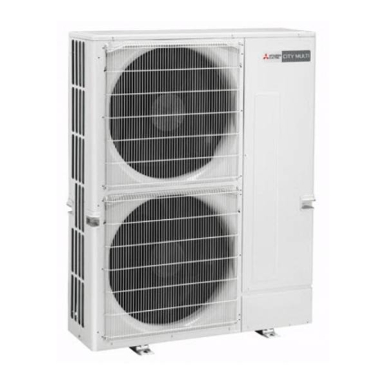
SPLIT-TYPE, HEAT PUMP AIR CONDITIONERS
TECHNICAL & SERVICE MANUAL
[Model name]
<Outdoor unit>
PUMY-P100VHM
PUMY-P125VHM
PUMY-P140VHM
OUTDOOR UNIT
NOTE :
· This service manual describes technical data of outdoor unit.
As for indoor units, refer to its service manual.
· RoHS compliant products have <G> mark on the spec name plate.
· For servicing of RoHS compliant products, refer to the RoHS PARTS LIST.
[Service Ref.]
PUMY-P100VHM
PUMY-P125VHM
PUMY-P140VHM
CONTENTS
1. SAFETY PRECAUTION····································2
2. OVERVIEW OF UNITS······································5
3. SPECIFICATIONS ·············································7
4. DATA ·································································8
5. OUTLINES AND DIMENSIONS ······················18
6. WIRING DIAGRAM ·········································19
8. TROUBLESHOOTING ····································30
9. ELECTRICAL WIRING····································70
10. REFRIGERANT PIPING TASKS·····················73
11. DISASSEMBLY PROCEDURE························77
12. PARTS LIST ····················································82
13. RoHS PARTS LIST ·········································85
Model name
indication
14. OPTIONAL PARTS··························Back Cover
August 2006
No. OC376
REVISED EDITION-A
HFC
utilized
R410A
Revision:
· PUMY-P100VHM and
PUMY-P140VHM are
added in REVISED
EDITION-A.
· RoHS PARTS LIST has
been added.
· Some descriptions have
been modified.
· Please void OC376.
Advertisement
Table of Contents

Related Manuals for Mitsubishi Electric PUMY-P100VHM


Summary of Contents for Mitsubishi Electric PUMY-P100VHM
-
Page 1: Table Of Contents
SPLIT-TYPE, HEAT PUMP AIR CONDITIONERS August 2006 No. OC376 REVISED EDITION-A utilized R410A TECHNICAL & SERVICE MANUAL [Service Ref.] [Model name] Revision: · PUMY-P100VHM and <Outdoor unit> PUMY-P140VHM are PUMY-P100VHM added in REVISED PUMY-P100VHM EDITION-A. PUMY-P125VHM · RoHS PARTS LIST has PUMY-P125VHM been added. -
Page 2: Safety Precaution
SAFETY PRECAUTION 1-1. CAUTIONS RELATED TO NEW REFRIGERANT Cautions for units utilizing refrigerant R410A Use new refrigerant pipes. Do not use refrigerant other than R410A. Avoid using thin pipes. If other refrigerant (R22 etc.) is used, chlorine in refrige- rant can cause deterioration of refrigerant oil etc. Use a vacuum pump with a reverse flow check Make sure that the inside and outside of refrige- valve. - Page 3 [1] Cautions for service (1) Perform service after collecting the refrigerant left in unit completely. (2) Do not release refrigerant in the air. (3) After completing service, charge the cycle with specified amount of refrigerant. (4) When performing service, install a filter drier simultaneously. Be sure to use a filter drier for new refrigerant.
- Page 4 Cautions for refrigerant piping work New refrigerant R410A is adopted for replacement inverter series. Although the refrigerant piping work for R410A is same as for R22, exclusive tools are necessary so as not to mix with different kind of refrigerant. Furthermore as the working pressure of R410A is 1.6 time higher than that of R22, their sizes of flared sections and flare nuts are different.
-
Page 5: Overview Of Units
OVERVIEW OF UNITS 2-1. UNIT CONSTRUCTION Outdoor unit PUMY-P100VHM PUMY-P125VHM PUMY-P140VHM Indoor Capacity Type 20 ~ Type 125 Type 20 ~ Type 140 unit that Number of units 1~ 6 unit 1~ 8 unit can be connected Total system wide capacity... -
Page 6: Unit Specifications
2-2. UNIT SPECIFICATIONS (1) Outdoor Unit Service Ref. PUMY-P100VHM PUMY-P125VHM PUMY-P140VHM Cooling (kW) 11.2 14.0 15.5 Capacity Heating (kW) 12.5 16.0 18.0 Motor for compressor (kW) Cooling / Heating capacity indicates the maximum value at operation under the following condition. -
Page 7: Specifications
SPECIFICATIONS PUMY-P100VHM PUMY-P125VHM PUMY-P140VHM Cooling Capacity 11.2 14.0 15.5 Heating Capacity 12.5 16.0 18.0 Input ( Cool ) 3.34 4.32 5.35 Input Current ( Cool ) 15.4/14.8/14.1, 15.4 20.0/19.1/18.3, 20.0 24.7/23.6/22.7,24.7 Power factor ( Cool ) 98.4 98.4 98.4 Input ( Heat ) 3.66... -
Page 8: Data
DATA 4-1. COOLING AND HEATING CAPACITY AND CHARACTERISTICS 4-1-1. Method for obtaining system cooling and heating capacity: To obtain the system cooling and heating capacity and the electrical characteristics of the outdoor unit, first add up the ratings of all the indoor units connected to the outdoor unit (see table below), and then use this total to find the standard capacity with the help of the tables on 4-2.STANDARD CAPACITY DIAGRAM. - Page 9 4-2. STANDARD CAPACITY DIAGRAM 4-2-1. PUMY-P100VHM *Before calculating the sum of total capacity of indoor units,please convert the value into the kW model capacity following the formula on 4-1-1. Capacity ( kW ) Power Consumption ( kW ) Current ( A ) /220V...
- Page 10 Capacity ( kW ) Power Consumption ( kW ) Current ( A ) /220V Current ( A ) /230V Current ( A ) /240V Total capacity of Cooling Heating Cooling Heating Cooling Heating Cooling Heating Cooling Heating indoor units* 11.10 12.38 3.27 3.62...
- Page 11 4-2-2. PUMY-P125VHM *Before calculating the sum of total capacity of indoor units,please convert the value into the kW model capacity following the formula on 4-1-1. Capacity(kW) Power Consumption(kW) Current(A)/ 220V Current(A)/ 230V Current(A)/ 240V Total capacity of Cooling Heating Cooling Heating Cooling Heating...
- Page 12 Capacity(kW) Power Consumption(kW) Current(A)/ 220V Current(A)/ 230V Current(A)/ 240V Total capacity of Cooling Heating Cooling Heating Cooling Heating Cooling Heating Cooling Heating indoor units* 3.92 3.98 18.1 18.4 17.3 17.6 16.6 16.9 13.10 14.88 3.96 4.02 18.3 18.6 17.5 17.8 16.8 17.0 13.20...
- Page 13 4-2-3. PUMY-P140VHM *Before calculating the sum of total capacity of indoor units,please convert the value into the kW model capacity following the formula on 4-1-1. Capacity ( kW ) Power Consumption ( kW ) Current ( A ) /220V Current ( A ) /230V Current ( A ) /240V Total capacity of Cooling...
- Page 14 Capacity ( kW ) Power Consumption ( kW ) Current ( A ) /220V Current ( A ) /230V Current ( A ) /240V Total capacity of Cooling Heating Cooling Heating Cooling Heating Cooling Heating Cooling Heating indoor units* 14.60 16.80 4.92 5.23...
- Page 15 Individual capacity under stated conditions = total capacity under the stated conditions o total capacity at the rated time (3)Capacity correction factor curve Figure 2. PUMY-P100VHM Figure 1. PUMY-P100VHM PUMY-P125VHM PUMY-P125VHM PUMY-P140VHM...
- Page 16 4-3-2. Correcting Capacity for Changes in the Length of Refrigerant Piping (1) During cooling, to obtain the ratio (and the equivalent piping length) of the outdoor units rated capacity and the total in-use indoor capacity, first find the capacity ratio corresponding to the standard piping length from Figure 3, and then multiply by the cooling capacity from Figure 1 to obtain the actual capacity.
- Page 17 4-4. NOISE CRITERION CURVES PUMY-P100VHM SPL(dB) MODE LINE PUMY-P125VHM SPL(dB) MODE LINE COOLING COOLING HEATING HEATING NC-70 NC-70 NC-60 NC-60 NC-50 NC-50 NC-40 NC-40 NC-30 NC-30 APPROXIMATE APPROXIMATE THRESHOLD OF THRESHOLD OF HEARING FOR NC-20 HEARING FOR NC-20 CONTINUOUS CONTINUOUS...
-
Page 18: Outlines And Dimensions
OUTLINES AND DIMENSIONS PUMY-P100VHM Unit : mm PUMY-P125VHM PUMY-P140VHM... -
Page 19: Wiring Diagram
WIRING DIAGRAM PUMY-P100VHM PUMY-P125VHM PUMY-P140VHM SYMBOL NAME SYMBOL NAME SYMBOL NAME SYMBOL NAME Terminal Block <Power Supply> P.B. Power Circuit Board MULTI.B. Multi Controller Board CNAC Connector <To Noise Filter Circuit Board> Terminal Block <Transmission> Fuse <6.3A> CNDC Connector <To Noise Filter Circuit>... -
Page 20: Necessary Conditions For System Construction
NECESSARY CONDITIONS FOR SYSTEM CONSTRUCTION 7-1. TRANSMISSION SYSTEM SETUP... - Page 21 7-2. REFRIGERANT SYSTEM DIAGRAM Unit:mm<inch> PUMY-P100VHM PUMY-P125VHM PUMY-P140VHM Refrigerant flow in cooling Refrigerant flow in heating High pressure sensor Service Thermistor (TH7) (63HS) High pressure port Stop valve (Outdoor temperature) switch (63H) 4-way valve Refrigerant Gas pipe Solenoid <5/8> Strainer...
-
Page 22: System Control
7-3. SYSTEM CONTROL Example for the System • Example for wiring control cables, wiring method and address setting, permissible lengths, and the prohibited items are listed in the standard system with detailed explanation. The explanation for the system in this section : Use one single outdoor unit and multiple outdoor units for M-NET remote control system. - Page 23 • Name, Symbol and the Maximum Remote controller Units for Connection Symbol Name Maximum units for connection Outdoor unit Indoor unit One OC unit can be connected to 1-8 IC units (P100VHM : 1-6 IC units) M-NET remote Maximum two RC for one indoor unit, Maximum 16 RC for one OC controller Permissible Lengths Prohibited items...
- Page 24 B. Example of a group operation system with two or more outdoor units and a M-NET remote controller. (Address settings are necessary.) (51) (01) (02) (05) (06) M1M2 S M1 M2 S M1 M2 S M1 M2 S M1 M2 S M1 M2 S (101) (105)
- Page 25 • Name, Symbol, and the Maximum Units for Connection [ 500 meters (1.25mm • Max length via outdoor units : L [ 200 meters (1.25mm • Max transmission cable length : L [ 10 meters (0.5 to 1.25mm • Remote controller cable length : R If the length exceeds 10 meters, use a 1.25 mm shielded wire.
- Page 26 C. Example of a MA remote controller system (address setting is not necessary.) NOTE : In the case of same group operation, need to set the address that is only main indoor unit. Example of wiring control cables Wiring Method and Address Setting 1.
- Page 27 Permissible Lengths Prohibited items The MA remote controller and the Maximum transmission cable length [ 200m (1.25 mm M-NET remote controller cannot be used together with the indoor unit MA remote controller cable length [ 200m (0.3 ~ 1.25 mm of the same group.
- Page 28 D. Example of a group operation with two or more outdoor units and a MA remote controller. (Address settings are necessary.) (51) (01) (02) (05) (06) TB15 TB15 TB15 TB15 M1M2 S M1 M2 M1 M2 S M1 M2 S M1 M2 S M1 M2 S (53)
- Page 29 • Name, Symbol, and the Maximum Units for Connection [ 500 m (1.25 e or more) Max length via outdoor unit (M-NET cable): L and L [ 200 m (1.25 e or more) Max transmission cable length (M-NET cable): L and L and L and L...
-
Page 30: Troubleshooting
TROUBLESHOOTING 8-1. CHECK POINTS FOR TEST RUN 8-1-1. Procedures of test run (1) Before test run, make sure that following work is completed. • Installation related : Make sure that the panel of cassette type and electrical wiring is done. Otherwise electrical functions like auto vane will not operate normally. - Page 31 8-1-2. Special Function Operation and Settings (for M-NET Remote Controller) • It is necessary to perform “group settings” and “paired settings” at making group settings of different refrigerant systems (multiple outdoor unit). (A) Group settings: Enter the indoor unit controlled by the remote controller, check the content of entries, and clear entries, etc.
- Page 32 (2) Address check: Refer to section (1) regarding address entry. a) In making group settings: • Turn off the remote controller: Press the remote controller's ON/OFF button to stop operation (the indicator light will go off). • Locate the indoor unit address display mode: Press the FILTER and k buttons on the remote controller simultaneously and hold for two seconds.
- Page 33 8-1-3. Countermeasures for Error During Test Run • If a problem occurs during test run, a code number will appear in the temperature display area on the remote controller (or LED on the outdoor unit), and the air conditioning system will automatically cease operating. Determine the nature of the abnormality and apply corrective measures.
- Page 34 Display Meaning and detecting method Check points Causes 1 Over-heated compressor operation is 1 Check intake super heat. Abnormal high discharging temperature 1102 Abnormal if discharge temperature thermistor caused by shortage of refrigerant Check leakage of refrigerant. 2 Defective operation of stop valve (TH4) exceeds 125: or 110: continuously Charge additional refrigerant.
- Page 35 Display Meaning and detecting method Check points Causes 1 Gas leakage, Gas shortage 1 Check the refrigerant amount. Refrigerant shortage abnormality 1501 2 When heating operation, scant When the conditions of below detecting mode 1 or 2 are satisfied during the 2 Check the operation condition and refrigerant operation (When heating, compressor operation.
- Page 36 Display Meaning and detecting method Check points Causes 1 Malfunction of drain pump 1 Check if drain-up machine works. 2502 Malfunction of drain pump (DP) 1 Suspensive abnormality, if thermistor of 2 Defective drain 2 Check drain function. drain sensor is let heat itself and tempe- Clogged drain pump rature rises slightly.
- Page 37 Display Meaning and detecting method Check points Causes 1 Connector (CN50) contact failure Drain sensor (THd, DS) abnormality Check whether the indoor controller 2503 When the drain sensor detects short/open (insertion failure) board connector (CN50) is while the operation. disconnected or not. 2 Thermistor wiring disconnection or half Check whether the thermistor wiring is disconnected or not.
- Page 38 Display Meaning and detecting method Check points Causes 1 Decrease of power supply voltage 1 Check the facility of power supply. Abnormality such as overvoltage or voltage 4220 2 Disconnection of compressor wiring 2 Correct the wiring (U·V·W phase) to shortage 3 Defective 52C compressor.
- Page 39 Display Meaning and detecting method Check points Causes 5101 Suction temperature thermistor (TH21) abnormality 1 Connector (CN20) contact failure Check whether the connector When controller detects short (high (CN20) in the indoor controller board temp.)/open (low temp.) in thermistor is connected or not. during the operation, the operation stops 2 Thermistor wiring disconnection or Check whether the thermistor wiring...
- Page 40 Display Meaning and detecting method Check points Causes 5102 Liquid pipe temperature thermistor (TH22) abnormality When the thermistor detects short/open 1) Connector (CN21) contact failure Check whether the connector during the operation, the operation stops (CN21) in the indoor controller board and the operation changes to protect mode is connected or not.
- Page 41 Display Meaning and detecting method Check points Causes 5103 Gas pipe temperature thermistor (TH23) abnormality 1) Connector (CN29) contact failure Check whether the connector (CN29) When the thermistor detects short/open in the indoor controller board is after 3 minutes-continuous thermo ON connected or not.
- Page 42 Display Meaning and detecting method Check points Causes 5106 Outdoor temperature thermistor (TH7) abnormality 1) Connector (TH7) contact failure Check whether the connector (TH7) in the multi controller board is When controller detects short/open in connected or not. thermistor during the operation, the outdoor unit stops once and restarts operation in 3 minutes.
- Page 43 Display Meaning and detecting method Check points Causes 5201 Pressure sensor (63HS) abnormality When detected pressure in high-pressure 1) High-pressure sensor failure Check the high-pressure sensor. sensor is 1 MPa or less during the operation, the compressor stops and restarts operation in 3 minutes. When the detected pressure is 1 MPa or 2) Internal pressure decreases by gas Check the internal pressure.
- Page 44 Display Meaning and detecting method Check points Causes 6603 Transmission bus busy error Over error by collision 1) The transmission processor cannot Check whether the transmission line be transmitted since a short cycle of the indoor unit, fresh master, Abnormality when the state, which cannot voltage of the noise etc.
- Page 45 From the preceding page. Display Meaning and detecting method Check points Causes No ACK (Acknowledgement) 6607 Factor that not related to origin Abnormality which controller of the 1) Since the address switch was Turn off power supply of outdoor unit, sending side detects when there is no changed with the passed current ,the indoor unit fresh master and lossnay...
- Page 46 Display Meaning and detecting method Check points Causes 3) When the cause of displayed address 1) When operating with multi 6607 and attribute is on the remote controller refrigerant system indoor units, the side indoor units transmits the signal to the remote controller after the other (The indoor unit detects when there is no refrigerant system outdoor unit is...
- Page 47 From the previous page. Display Meaning and detecting method Check points Causes 6607 2) When synchronized operating with other refrigerant system lossnay, the indoor units transmit the signal to the lossnay after the lossnay and same refrigerant system outdoor unit is turned off or turned on again in 2 minutes, and detects abnormality.
- Page 48 Display Meaning and detecting method Check points Causes 6831 Signal reception abnormality (Remote Defect of the transmission and reception circuit of the remote controller. 6834 controller) Perform a check of the remote Following symptoms are regarded as controller. abnormality. Defect of the transmission and According to the results, perform the reception circuit of the indoor controller following process.
- Page 49 Display Meaning and detecting method Check points Causes 7101 Capacity code error When the connected indoor unit models The indoor unit models is not possible Check the model code registration cannot be connected, <7101> is displayed. to connect. switch (indoor controller board SW2) in the connected indoor unit.
-
Page 50: Remote Controller Diagnosis
8-2. REMOTE CONTROLLER DIAGNOSIS · MA remote controller is equipped with the diagnosis function If the air conditioner cannot be operated from the remote controller, diagnose the remote controller as explained below. First, check that the power-on indicator is lit. If the correct voltage (DC12 V) is not supplied to the remote controller, the indicator will not light. - Page 51 8-3. REMOTE CONTROLLER TROUBLE CENTRALLY CONTROLLED 1Hr. ON OFF ˚C CLOCK CHECK FILTER CHECK MODE ˚C TEST RUN STAND BY ERROR CODE NOT AVAILABLE FUNCTION DEFROST “ ” indicator: Appears when current is carried. TEMP. ON/OFF FILTER CHECK TEST TIMER SET (M-NET Remote controller) (1) For M-NET remote controller systems Symptom or inspection code...
- Page 52 8-4. THE FOLLOWING SYMPTOM DO NOT REPRESENT TROUBLE (EMERGENCY) Symptom Display of remote controller CAUSE Even the cooling (heating) "Cooling (Heating)" blinks The indoor unit can not cool (heat) if other indoor units are heating operation selection button (cooling). is pressed, the indoor unit cannot be operated.
- Page 53 8-5. INTERNAL SWITCH FUNCTION TABLE PUMY-P100VHM PUMY-P125VHM PUMY-P140VHM Operation in Each Switch Setting Switch Step Function Remarks When to Set <Factory Settings> SWU1 1st digit Before turning the power on SWU2 SWU2 SWU1 SWU2 SWU1 2nd digit (2nd digit) (1st digit)
- Page 54 Operation in Each Switch Setting Switch Step Function Remarks When to Set — — — — <Factory Settings> Switch of current limitation reading Before turning the Normal Enable in a different way power on. — — — — 2 3 4 5 6 7 8 Restriction of maximum Can be set when Normal...
- Page 55 8-6. OUTDOOR UNIT INPUT/OUTPUT CONNECTOR State (CN51) Distant control External output board adapter Relay circuit Outdoor unit control board CN51 Preparations Maximum cable in the field length is 10m : Error display lamp : Compressor operation lamp X, Y : Relay (Coil standard of 0.9W or less for DC 12V) Auto change over (CN3N) Distant control External output...
- Page 56 8-7. HOW TO CHECK THE PARTS PUMY-P100VHM PUMY-P125VHM PUMY-P140VHM Parts name Check points Thermistor (TH3) Disconnect the connector then measure the resistance using a tester. <Outdoor pipe> (Surrounding temperature 10:~30:) Thermistor (TH4) Normal Abnormal <Discharge> 160k"~410k" Thermistor (TH6) <Low pressure saturated temperature>...
- Page 57 Check method of DC fan motor (fan motor / outdoor controller circuit board) Notes · High voltage is applied to the connecter (CNF1, 2) for the fan motor. Give attention to the service. · Do not pull out the connector (CNF1, 2) for the motor with the power supply on. (It causes trouble of the outdoor controller circuit board and fan motor.) Self check...
- Page 58 8-8. HOW TO CHECK THE COMPONENTS <Thermistor feature chart> Low temperature thermistors • Thermistor <Outdoor pipe> (TH3) • Thermistor <Low pressure saturated temperature> (TH6) • Thermistor <Outdoor> (TH7) Thermistor R0 = 15k' ± 3% B constant = 3480 ± 2% =15exp{3480( 273+t –...
- Page 59 8-9. TEST POINT DIAGRAM Outdoor multi controller board PUMY-P100VHM PUMY-P125VHM PUMY-P140VHM CN51 CN102 External signal Connect to the M-P.B pump down Test run Forced defrost Model select output (Transmission power board) CN40,CN41 Demand/ Silent selection Centralized control power supply/ For storing...
- Page 60 W Usually, they are in a state of being short-circuited if they are broken. Outdoor power circuit board Measure the resistance in the following points (connectors, etc.). PUMY-P100VHM If they are short-circuited, it means that they are broken. 1. Check of POWER MODULE PUMY-P125VHM 1.Check of DIODE circuit...
- Page 61 Outdoor noise filter circuit board PUMY-P100VHM PUMY-P125VHM PUMY-P140VHM LO, NO Voltage of 220-240V AC is output TABS (Connect to the outdoor power circuit board) TABT CNAC1, CNAC2 220-240V AC (Connect to the outdoor controller circuit board (CNAC)) Primary current (Connect to the...
- Page 62 Transmission power board PUMY-P100VHM PUMY-P125VHM PUMY-P140VHM Connect to the outdoor multi controller board 1-2: 24–30V DC 3-4: 24–30V DC Connect to the outdoor noise filter circuit board 1–3 : 220–240V AC...
- Page 63 SW:setting 0..OFF 8-10. OUTDOOR UNIT FUNCTIONS 1..ON...
-
Page 70: Electrical Wiring
ELECTRICAL WIRING This chapter provides an introduction to electrical wiring for the CITY MULTI-S series, including notes concerning power wiring, wiring for control (transmission wires and remote controller wires), and the frequency converter. 9-1. OVERVIEW OF POWER WIRING Use a separate power supply for the outdoor unit and indoor unit. (1). - Page 71 9-3. DESIGN FOR CONTROL WIRING Please note that the types and numbers of control wires needed by the CITY MULTI-S series will depend on the remote controllers and whether they are linked with the system. 9-3-1. Selection number of control wires M-NET remote controller Remote controller used in system control operations.
- Page 72 9-6. METHOD FOR OBTAINING ELECTRICAL CHARACTERISTICS WHEN A CAPACITY AGREEMENT IS TO BE SIGNED WITH AN ELECTRIC POWER COMPANY The electrical characteristics of connected indoor unit system for air conditioning systems, including the MULTI-S series, will depend on the arrangement of the indoor and outdoor units. First read the data on the selected indoor and outdoor units and then use the following formulas to calculate the electrical characteristics before applying for a capacity agreement with the local electric power company.
-
Page 73: Refrigerant Piping Tasks
REFRIGERANT PIPING TASKS 10-1. REFRIGERANT PIPING SYSTEM Line-Branch Method Connection Examples (Connecting to Four Indoor Units) Outdoor Unit First Branch Indoor unit A+B+C+D+a+b+c+d+e [ 120m Total Piping Length Permissible A+B+C+D+e [ 80m Farthest Piping Length Length B+C+D+e [ 30m Farthest Piping Length After First Branch Height Difference in Indoor/Outdoor Section 30 meters or less (If the outdoor unit is lower, 20 meters or less) Permissible High/... - Page 74 Header-Branch Method Connection Examples (Connecting to Four Indoor Units) Outdoor Unit First Branch Indoor unit A+a+b+c+d+e+f [ 120m Total Piping Length Permissible A+f [ 80m Farthest Piping Length Length Farthest Piping Length After First Branch f is 30 meters or less Height Difference in Indoor/Outdoor Section 30 meters or less (If the outdoor unit is lower, 20 meters or less) Permissible High/...
- Page 75 Note: The total of downstream unit models in the table is the total of models as seen from point A in the figure below. Note: Pipe re-branching after the header branching is not possible. Method of Combined Branching of Lines and Headers Connection Examples (Connecting to Five Indoor Units)
-
Page 76: Precautions Against Refrigerant Leakage
10-2. PRECAUTIONS AGAINST REFRIGERANT LEAKAGE 10-2-1. Introduction (2) Calculate room volumes (K) and find the room with the smallest volume R410A refrigerant of this air conditioner is non-toxic and non-flammable but leaking of large amount from an indoor The part with represents the room with the smallest unit into the room where the unit is installed may be deleteri- volume. -
Page 77: Disassembly Procedure
DISASSEMBLY PROCEDURE OUTDOOR UNIT : PUMY-P100VHM PUMY-P125VHM PUMY-P140VHM OPERATING PROCEDURE PHOTOS & ILLUSTRATION 1. Removing the service panel and top panel Top panel fixing screws Top panel Figure 1 (1) Remove 3 service panel fixing screws (5 10) and slide... - Page 78 From the previous page. OPERATING PROCEDURE PHOTOS & ILLUSTRATION (6) Remove electrical parts box fixing screw (4 10) and Photo 4 detach the electrical parts box by pulling it upward. The Electrical parts box electrical parts box is fixed with 2 hooks on the left and 1 hook on the right.
- Page 79 PHOTOS OPERATING PROCEDURE 6. Removing the thermistor <Outdoor pipe> (TH3) and thermistor <Discharge> (TH4) Photo 7 (1) Remove the service panel. (See figure 1.) Thermistor (2) Disconnect the connectors, TH3 (white) and TH4 (white), <Outdoor pipe> on the Multi controller board in the electrical parts box. (TH3) (3) Loosen the clamp for the lead wire in the rear of the electrical parts box.
- Page 80 OPERATING PROCEDURE PHOTOS 9. Removing solenoid valve coil <Bypass valve> (SV1) and Photo 9 bypass valve (1) Remove the service panel. (See figure 1.) (2) Remove the top panel. (See figure 1.) (3) Remove 3 right side panel fixing screws (5 10) in the rear of the unit and remove the right side panel.
- Page 81 OPERATING PROCEDURE PHOTOS Photo 11 12. Removing the compressor (MC) (1) Remove the service panel. (See figure 1.) (2) Remove the top panel. (See figure 1.) (3) Remove 2 front cover panel fixing screws (5 10) and remove the front cover panel. (See photo 3.) (4) Remove 2 back cover panel fixing screws (5 10) and remove the back cover panel.
-
Page 82: Parts List
PARTS LIST (non-RoHS compliant) 12-1. FUNCTIONAL PARTS PUMY-P125VHM... - Page 83 Part numbers that are circled are not shown in the figure. Price ty/set Wiring Recom- Remarks Part No. Part Name Specification Diagram mended (Drawing No.) PUMY-P125VHM Symbol Unit Amount MF1,2 R01 E44 221 FAN MOTOR R01 E01 115 PROPELLER FAN R01 E02 097 R01 E06 413 CHARGE PLUG...
- Page 84 12-2. STRUCTURAL PARTS PUMY-P125VHM 5 6 7 ty/set Wiring Recom- Price Remarks Part No. Part Name Specification Diagram mended (Drawing No.) PUMY-P125VHM Symbol Unit Amount – F.ST SCREW (DG12F536H10) (5 10) T7W E02 662 SIDE PANEL (L) T7W E02 691 FAN GRILLE T7W E02 667 FRONT PANEL...
-
Page 85: Rohs Parts List
RoHS PARTS LIST 13-1. STRUCTURAL PARTS PUMY-P100VHM PUMY-P125VHM PUMY-P140VHM 5 6 7 ty/set Wiring Recom- Price Remarks Part No. Part Name Specification Diagram mended PUMY- (Drawing No.) Symbol Unit Amount P100,125,140VHM – F.ST SCREW (DG12F536H10) (5 10) T7W E03 662... - Page 86 13-2. FUNCTIONAL PARTS PUMY-P100VHM PUMY-P125VHM PUMY-P140VHM...
- Page 87 Part numbers that are circled are not shown in the figure. Price ty/set Wiring Recom- Remarks Part No. Part Name Specification Diagram mended PUMY- (Drawing No.) Symbol Unit Amount P100, 125, 140VHM MF1,2 R01 E44 221 FAN MOTOR R01 E08 115 PROPELLER FAN R01 E09 097 R01 E14 413...
-
Page 88: Optional Parts
CMY-Y64-G-E CMY-Y68-G-E HEAD OFFICE : TOKYO BLDG., 2-7-3, MARUNOUCHI, CHIYODA-KU, TOKYO100-8310, JAPAN cCopyright 2006 MITSUBISHI ELECTRIC ENGINEERING CO., LTD. Distributed in Aug. 2006 No. OC376 REVISED EDITION-A PDF 8 New publication, effective Aug. 2006 Distributed in Mar. 2006 No. OC376 PDF 9...
Need help?
Do you have a question about the PUMY-P100VHM and is the answer not in the manual?
Questions and answers