Table of Contents
Advertisement
Advertisement
Table of Contents

Subscribe to Our Youtube Channel
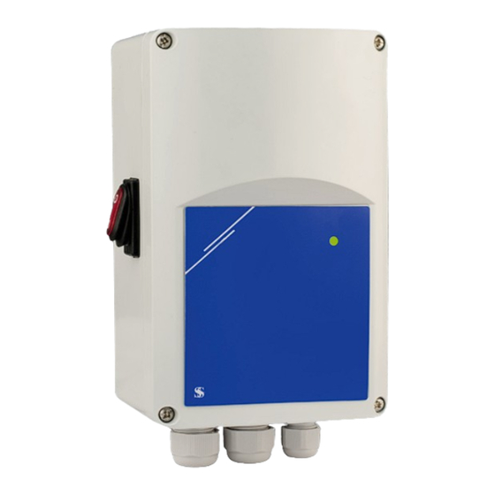
Summary of Contents for Sentera EVS Series
- Page 1 ELECTRONIC FAN SPEED CONTROLLER Mounting and operating instructions...
-
Page 2: Table Of Contents
STANDARDS WIRING AND CONNECTIONS OPERATIONAL DIAGRAMS MOUNTING INSTRUCTIONS IN STEPS VERIFICATION OF INSTALLATION INSTRUCTIONS OPERATING INSTRUCTIONS MODBUS REGISTER MAPS TRANSPORT AND STOCK KEEPING INFORMATION WARRANTY INFORMATION AND RESTRICTIONS MAINTENANCE MIW-EVS-DM-EN-000 - 14 / 03 / 2016 2 - 16 www.sentera.eu... -
Page 3: Safety And Precautions
In case there are any questions that are not answered, please contact your technical support or consult a professional. MIW-EVS-DM-EN-000 - 14 / 03 / 2016 3 - 16 www.sentera.eu back to the table of contents... -
Page 4: Product Description
Protection standard: IP54 (according to EN 60529) ■ Operating ambient conditions: ► temperature: - 20—40 °C rel. humidity: < 95 % rH (non-condensing) ► ■ Storage temperature: -40—50 °C MIW-EVS-DM-EN-000 - 14 / 03 / 2016 4 - 16 www.sentera.eu back to the table of contents... -
Page 5: Standards
(min. 2,5 VDC and > 30 ms ) Ground Cable cross section: max. 2,5 mm Connections Cable gland clamping range: 3—6 mm / 5—10 mm MIW-EVS-DM-EN-000 - 14 / 03 / 2016 5 - 16 www.sentera.eu back to the table of contents... -
Page 6: Operational Diagrams
20 mA 0 VDC / t [s] 10 VDC / 0 mA 20 mA Soft start time Soft start time [VDC]/ [VDC]/ [mA] [mA] MIW-EVS-DM-EN-000 - 14 / 03 / 2016 6 - 16 www.sentera.eu back to the table of contents... -
Page 7: Range
Soft start Start Stop Start Stop Soft start Soft start Start Operation Start Operation Stop duration timer duration duration duration timer timer Operation time MIW-EVS-DM-EN-000 - 14 / 03 / 2016 7 - 16 www.sentera.eu back to the table of contents... -
Page 8: Mounting Instructions In Steps
230 VAC, Modbus RTU A 50 / 60 Hz Supply output +12 VDC / 1 mA Analogue input 0—10 VDC / 0—20 mA MIW-EVS-DM-EN-000 - 14 / 03 / 2016 8 - 16 www.sentera.eu back to the table of contents... -
Page 9: Miw-Evs-Dm-En-000 - 14 / 03 / 2016
Adjust the OFF level value by trimmer (if necessary). The default setting is 0 VAC. See Fig. 8 Off level trimmer. Fig. 6 Max. speed trimmer Fig. 7 Min. speed trimmer Fig. 8 Off level trimmer MIW-EVS-DM-EN-000 - 14 / 03 / 2016 9 - 16 www.sentera.eu back to the table of contents... -
Page 10: Verification Of Installation Instructions
Fig. 9 Communication detection indication ATTENTION The status of the LEDs can be checked only when the unit is energised. Take the relevant safety measures! MIW-EVS-DM-EN-000 - 14 / 03 / 2016 10 - 16 www.sentera.eu back to the table of contents... -
Page 11: Operating Instructions
► OFF level is enabled and the analogue input signal is below the OFF level value. ► Fig. 10 Operation indication MIW-EVS-DM-EN-000 - 14 / 03 / 2016 11 - 16 www.sentera.eu back to the table of contents... -
Page 12: Modbus Register Maps
Remote control input 0—1 Enabled L1 control unsigned int. L1 control 0—1 ON/Stand-by LED unsigned int. ON/Stand-by LED 0—2 Stand-by 15-20 Reserved, returns 0 MIW-EVS-DM-EN-000 - 14 / 03 / 2016 12 - 16 www.sentera.eu back to the table of contents... - Page 13 100 = 100 % Us 32-40 Reserved, returns 0 If you want to find out more about Modbus over serial line, please visit: http://www.modbus.org/docs/Modbus_over_serial_line_V1_02.pdf MIW-EVS-DM-EN-000 - 14 / 03 / 2016 13 - 16 www.sentera.eu back to the table of contents...
- Page 14 L1 is ‘0’ = OFF (0 VAC). Otherwise it is ‘1’ = On (230 VAC) MIW-EVS-DM-EN-000 - 14 / 03 / 2016 14 - 16 www.sentera.eu back to the table of contents...
- Page 15 (30— 70 % Us). ■ Holding register 15 (40015) sets the OFF level state. The default value is ‘0’ (disabled). ‘1’ is for enabled. MIW-EVS-DM-EN-000 - 14 / 03 / 2016 15 - 16 www.sentera.eu back to the table of contents...
-
Page 16: Transport And Stock Keeping Information
Pay attention that no fluids enter the unit. Only reconnect it to the supply when it is completely dry. MIW-EVS-DM-EN-000 - 14 / 03 / 2016 16 - 16 www.sentera.eu back to the table of contents...


Need help?
Do you have a question about the EVS Series and is the answer not in the manual?
Questions and answers