Table of Contents
Advertisement
Quick Links
8x931HA USB Customer Hub
Product Features
Intel 8x931HA USB Peripheral Controller
8x931HA USB Hub has One Internal
Downstream, and Four External
Downstream Ports
USB Hub
— Connectivity Management
— Downstream Device Connect/
Disconnect Detection
— Power Management, Including Suspend
and Resume
— Bus Fault Detection and Recovery
— Full and Low Speed Downstream
Device Support
The Intel 8x931HA USB Customer Hub (CHUB) is a hardware reference design for the USB
system designer.
The Intel 8x931HA USB CHUB incorporates a fully functional Intel 8x931HA USB Peripheral
Controller. The CHUB has undergone the same level of testing required of a commercial USB
Hub product, such as USB PlugFest compliance and Intel System Integration and Validation
testing.
This document contains information on products in the sampling and initial production phases of
development. The specifications are subject to change without notice. Verify with your local Intel
sales office that you have the latest datasheet before finalizing a design.
Advance Information Datasheet
Hardware Reference Design
— Status LED
— Self/Bus Power Switch Options
— Reset Switch
— Internal Program Memory Option
— Uses High Side Power Switch for USB
Power Management
—provides current limiting
—provides thermal shutdown
—500mA minimum continous load
current per channel
Order Number: 273141-003
June 1998
Advertisement
Table of Contents

Subscribe to Our Youtube Channel
Related Manuals for Intel 8x931HA


Summary of Contents for Intel 8x931HA
-
Page 1: Product Features
— Full and Low Speed Downstream Device Support The Intel 8x931HA USB Customer Hub (CHUB) is a hardware reference design for the USB system designer. The Intel 8x931HA USB CHUB incorporates a fully functional Intel 8x931HA USB Peripheral Controller. - Page 2 Information in this document is provided in connection with Intel products. No license, express or implied, by estoppel or otherwise, to any intellectual property rights is granted by this document. Except as provided in Intel’s Terms and Conditions of Sale for such products, Intel assumes no liability whatsoever, and Intel disclaims any express or implied warranty, relating to sale and/or use of Intel products including liabil ity or warranties relating to fitness for a particular purpose, merchantability, or infringement of any patent, copyright or other intellectual property right.
-
Page 3: Table Of Contents
Bill of Materials ......................13 Schematics ......................... 15 Figures Intel 8x931HA USB Customer HUB Block Diagram..........6 Top View of CHUB ....................6 Bottom Label for CHUB Device................7 Top and Bottom View of CHUB Encasing ............11 Device Dimensions....................11 Tables Electronic Information.................... -
Page 5: Introduction
8x931HA USB Customer Hub Introduction The Intel 8x931HA USB Customer HUB (CHUB) is a hardware reference design for the USB system designer. The CHUB serves as an evaluation platform and reference design for use in constructing a USB HUB that incorporates Intel’s 8x931HA USB Peripheral Controller. -
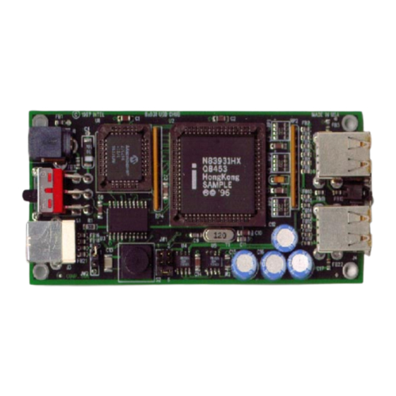
Page 6: Board Connector Interface
8x931HA USB Customer Hub Figure 1. Intel 8x931HA USB Customer HUB Block Diagram Port0 Upstream D0-D7 32Kx8 74ACT373 8x931 Hx EPROM Latch Intel USB HUB AD0-AD7 A0-A7 12 MHz Clock A8-A15 Port2 Port4 Port3 Port5 Status A4601-01 Board Connector Interface Figure 2 illustrates the major components of the CHUB board. -
Page 7: Bottom Label For Chub Device
8x931HA USB Customer Hub Figure 3. Bottom Label for CHUB Device Port 2 Status Port 4 Port 5 Port 3 Intel 8x931HA USB Customer HUB NOT F.C.C. APPROVED Self Powered: 500mA/port Bus Powered: 100mA/port Voltage In: 5.0V +/-2% A4600-01 Table 3. CHUB Connectors... -
Page 8: Functional Description
Internal Program Memory Option Intel’s 8x931HA USB Peripheral hub controller comes preprogrammed with an internal ROM code which enumerates and configures the hub to a minimal default configuration. To use this internal ROM the user must: 1.) Carefully remove plastic enclosure. -
Page 9: Firmware
This bug in the beta version, in conjunction with the values reported in the hub’s port power control mask field, caused the operating system to fail to issue "Set Port Power" commands to the downstream ports on Intel’s 8x931Hx hub peripheral controller. -
Page 10: Input Power Specification
USB cable. In Self powered mode, Intel has specified the power supply be 5.0 V +/- 2%. Typically, 5V power supplies do not specify to this tight tolerance. Typical power supplies are +/- 5%. The CHUB will operate and run with a 5V +/-5% power supply, but will not have the allocated voltage drop budget allowed. -
Page 11: Mechanical Data
8x931HA USB Customer Hub Mechanical Data Module Dimensions This section provides the physical dimensions for the Intel 8x931HA USB CHUB plastic encasing. Figure 4 shows the top and bottom views of the CHUB encasing. Figure 5 gives the device dimensions and connector orientations. -
Page 12: Plastic Encasing Removal And Assembly Procedures
8x931HA USB Customer Hub Plastic Encasing Removal and Assembly Procedures The CHUB uses a molded plastic encasing to protect the PCB. Removing and assembling the plastic encasing requires some care since there are no screws used in the assembly of the PCB and the plastic encasing. -
Page 13: Bill Of Materials
This following table contains the bill of materials used in building the CHUB. Reference the specific manufacturer’s datasheet for specifications. Intel does not recommend or endorse any suppliers. The inclusion of this list should not be construed as a recommendation or an endorsement of these particular suppliers. -
Page 14: Bill Of Materials (Chub Rev. D)
8x931HA USB Customer Hub Table 6. Bill of Materials (CHUB Rev. D) Advance Information Datasheet... -
Page 15: Schematics
8x931HA USB Customer Hub Schematics This section displays schematics for the 8x931HA CHUB board. These schematics are also on the diskette(s) provided with this kit. These schematics may also be downloaded via the Intel web site (see Table 1 for URL). - Page 16 RESET P0.[0:7] A[0:7]...
Need help?
Do you have a question about the 8x931HA and is the answer not in the manual?
Questions and answers