Table of Contents
Advertisement
Gearless Lift Machine
WSG-08
with caliper disk brake
Operating Instructions
Reprinting, translation or reproduction in any form -
whether in part or in full - requires the prior written
permission of WITTUR Holding GmbH.
Änderungen vorbehalten!
Gearless Lift Machines
beamer 2
WSG-08.1
WSG-08.2
WSG-08.3
WSG-08.4
with caliper disk brake
WITTUR Holding GmbH
Rohrbachstraße 26-30 • D-85259 Wiedenzhausen, Germany
Tel. +49 (0) 81 34/18-0 • Fax +49 (0) 81 34/18-49
http://www.wittur.com, E-mail: info@wittur.com
Seite/page
Datum/date
Stand/version
Wittur Holding GmbH reserves the right to make
changes in the information and pictures contained in
these operating instructions without prior notice.
Subject to changes without notice!
1
12.08.2016
0.18
Advertisement
Chapters
Table of Contents

Subscribe to Our Youtube Channel
Related Manuals for WITTUR Beamer 2 Series


Summary of Contents for WITTUR Beamer 2 Series
- Page 1 Tel. +49 (0) 81 34/18-0 • Fax +49 (0) 81 34/18-49 http://www.wittur.com, E-mail: info@wittur.com Reprinting, translation or reproduction in any form - Wittur Holding GmbH reserves the right to make whether in part or in full - requires the prior written changes in the information and pictures contained in permission of WITTUR Holding GmbH.
- Page 2 WSG - 08..with caliper disk brake WITTUR Electric Drives GmbH reserves the right to correct or change the contents of this manual and these product details without prior notice. expressly reserve the right to make technical changes which improve the lift machines or their safety stan- dards without prior notice.
-
Page 3: Table Of Contents
Gearless Lift Machine Seite/page Datum/date 12.08.2016 WSG-08 with caliper disk brake Stand/version 0.18 Operating Instructions Contents 1. General safety instructions........................4 2. Product description ..........................6 3. Nameplate..............................6 4. Scope of supply ............................8 5. Transport and storage ..........................8 6. Installation..............................9 7. Electrical connection ..........................10 7.1. -
Page 4: General Safety Instructions
Gearless Lift Machine Seite/page Datum/date 12.08.2016 WSG-08 with caliper disk brake Stand/version 0.18 Operating Instructions 1. General safety instructions Explanation of symbols used in these instructions • Non-compliance with the instructions contained in the operating instructions or other documentation sup- means that death or serious injury to per- plied sons or serious damage to property will... - Page 5 Gearless Lift Machine Seite/page Datum/date 12.08.2016 WSG-08 with caliper disk brake Stand/version 0.18 Operating Instructions • Repairs may only be carried out by the manufacturer or an authorised repair agency. Unauthorised opening and tam- pering may result in injuries to persons and property.
-
Page 6: Product Description
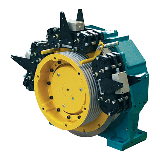
Gearless Lift Machine Seite/page Datum/date 12.08.2016 WSG-08 with caliper disk brake Stand/version 0.18 Operating Instructions 2. Product description The compact flat-type gearless WSG-08 lift machines are connected to the power supply by a signal plug connec- designed for gearless traction sheave lifts with or with- tor (12). - Page 7 Gearless Lift Machine Seite/page Datum/date 12.08.2016 WSG-08 with caliper disk brake Stand/version 0.18 Operating Instructions Main bearing head Measuring system (ECN 1313) Laminated stator core Measuring system connection Magnet ring Motor connection Rotor caliper disk brake Traction sheave Brake connection Thread for return motion device Ever plate Shaft...
-
Page 8: Scope Of Supply
Gearless Lift Machine Seite/page Datum/date 12.08.2016 WSG-08 with caliper disk brake Stand/version 0.18 Operating Instructions 4. Scope of supply • Lift machine WSG-08 according to order specification Options: • Operating instructions • Release lever set with remotely controlled bowden cable •... -
Page 9: Installation
Gearless Lift Machine Seite/page Datum/date 12.08.2016 WSG-08 with caliper disk brake Stand/version 0.18 Operating Instructions 6. Installation Be sure to check the base frame or founda- temperature, the reduction factors k shown in the tion loads by calculation before installing diagram below must be used. -
Page 10: Electrical Connection
Gearless Lift Machine Seite/page Datum/date 12.08.2016 WSG-08 with caliper disk brake Stand/version 0.18 Operating Instructions 7. Electrical connection 7.1. General 7.2. Motor connection / Winding protection The electrical connection may only be made The electrical connection of the motor and the winding by a qualified electrician. - Page 11 Gearless Lift Machine Seite/page Datum/date 12.08.2016 WSG-08 with caliper disk brake Stand/version 0.18 Operating Instructions Handling Motor connection diagram M 20 für Kabeldurchmesser 7-12 mm • Hold the bared con- M 20 ductor against the for cable diameter terminal. 7-12 mm W1 V1 U1 2 1 für Kabel-Æ...
- Page 12 Gearless Lift Machine Seite/page Datum/date 12.08.2016 WSG-08 with caliper disk brake Stand/version 0.18 Operating Instructions Earthing For safety reasons, it is very important that the motor be properly and carefully earthed. It is essential to use the earthing terminal in the terminal box. In addition, an earth- ing screw is provided on the motor frame for the connection of a protective or earth- Warning...
-
Page 13: Speed/Position Measuring System
Gearless Lift Machine Seite/page Datum/date 12.08.2016 WSG-08 with caliper disk brake Stand/version 0.18 Operating Instructions 7.3. Speed/Position measuring system The basic version of the lift machines is equipped with a 7.3.1. Measuring system ECN 1313 ECN 1313 sine-cosine encoder from Heidenhain GmbH. Number of sine-cosine The encoder is connected via a 17-pole signal plug con- periods per rotation:... -
Page 14: Brake
Gearless Lift Machine Seite/page Datum/date 12.08.2016 WSG-08 with caliper disk brake Stand/version 0.18 Operating Instructions 7.4. Brake Monitoring the brakes The switching state of the brakes is monitored using The brakes are supplied with d.c. voltage by an overexci- dust-proof micro switches with gold contacts. The con- tation rectifier which is installed in the terminal box for tacts are designed as n.c. - Page 15 Gearless Lift Machine Seite/page Datum/date 12.08.2016 WSG-08 with caliper disk brake Stand/version 0.18 Operating Instructions Circuitry suggestion for brake control Änderungen vorbehalten! Subject to changes without notice!
-
Page 16: Commissioning
Gearless Lift Machine Seite/page Datum/date 12.08.2016 WSG-08 with caliper disk brake Stand/version 0.18 Operating Instructions 8. Commissioning The following points should be checked or completed: • Is the measuring system properly connected? • Remove all securing, auxiliary and installation tools •... -
Page 17: Operation And Maintenance
Gearless Lift Machine Seite/page Datum/date 12.08.2016 WSG-08 with caliper disk brake Stand/version 0.18 Operating Instructions 9. Operation and maintenance 9.1. General 9.2. Maintenance intervals The regulations concerning operation, maintenance and Check the thickness every six inspection in accordance with the applicable safety regu- see section 9.6. -
Page 18: Lubricating Instructions
Gearless Lift Machine Seite/page Datum/date 12.08.2016 WSG-08 with caliper disk brake Stand/version 0.18 Operating Instructions 9.3. Lubricating instructions The main bearing (DE self-aligning roller bearing) has been filled at the factory with a quantity of grease suffi- cient for the nominal service life of the machine. No regreasing is required or recommended under normal service conditions. -
Page 19: Emergency Evacuation
Gearless Lift Machine Seite/page Datum/date 12.08.2016 WSG-08 with caliper disk brake Stand/version 0.18 Operating Instructions 9.4. Emergency evacuation The lift design engineer WSG- must always provide for an electric return 08.1/2/3 08.4 (two brakes) (three brakes) motion control or for Note Item in a manual rewinder... - Page 20 Gearless Lift Machine Seite/page Datum/date 12.08.2016 WSG-08 with caliper disk brake Stand/version 0.18 Operating Instructions Installation Install the manual brake releasing device while the brake 5. Then insert the sleeve ends. A certain amount of effort is disconnected from the power supply. is needed, as the cables require some preloading.
- Page 21 Gearless Lift Machine Seite/page Datum/date 12.08.2016 WSG-08 with caliper disk brake Stand/version 0.18 Operating Instructions A mechanical return motion device can be fitted at the traction sheave types and brake arrangements must be operator's own responsibility if the lift needs to be taken into account in regard to the arrangement of the moved manually in case of a breakdown or if the car is return motion device.
-
Page 22: Replacing The Traction Sheave
Gearless Lift Machine Seite/page Datum/date 12.08.2016 WSG-08 with caliper disk brake Stand/version 0.18 Operating Instructions 9.5. Replacing the traction sheave The traction sheave can work loose if it is not properly installed. Danger Disassembly • Power off the system and safeguard against uninten- tional reclosing. -
Page 23: Replacing The Brakes
Gearless Lift Machine Seite/page Datum/date 12.08.2016 WSG-08 with caliper disk brake Stand/version 0.18 Operating Instructions 9.6. Replacing the brakes Disassembly • Remove the two M6 x 40 spring bolts. • Release the brake manually using the two M6 x 65 release screws supplied (see figure). -
Page 24: Modification Of Brake Arrangement Wsg-08.1-3
Gearless Lift Machine Seite/page Datum/date 12.08.2016 WSG-08 with caliper disk brake Stand/version 0.18 Operating Instructions 9.7. Modification of brake arrangement WSG-08.1-3 The modification may only be made by a • Take off the brake carefully and remove the pins. qualified personnel. Life-threatening situa- tion in case of misapplication ! Danger Fitting the brake with flange (1) -
Page 25: Switch-Adjusting For Monitoring The Brake
Gearless Lift Machine Seite/page Datum/date 12.08.2016 WSG-08 with caliper disk brake Stand/version 0.18 Operating Instructions 9.8. Switch-adjusting for monitoring the brake • Remove the brake terminal box (A) • Switch on the brake magnet; s has to be 0 mm. •... -
Page 26: Replacing The Measuring System
Gearless Lift Machine Seite/page Datum/date 12.08.2016 WSG-08 with caliper disk brake Stand/version 0.18 Operating Instructions 9.9. Replacing the measuring system The measuring system is only accessible from the rear side of the motor. Spannring am Mess-System Note clamping ring on Disassemble the measuring system only if measuring system this is necessary because of a defect. -
Page 27: Testing The Brake System To En 81-1
Gearless Lift Machine Seite/page Datum/date 12.08.2016 WSG-08 with caliper disk brake Stand/version 0.18 Operating Instructions 9.10. Testing the brake system to EN 81 The brake system should be tested with the Separate operation of the individual brakes car about halfway down the shaft. If any There are several possible ways of operating the brakes motor short-circuit connections have been separately:... -
Page 28: Trouble Shooting
Gearless Lift Machine Seite/page Datum/date 12.08.2016 WSG-08 with caliper disk brake Stand/version 0.18 Operating Instructions 9.11. Trouble shooting Fault Possible cause Remedy Motor does not start, operates out of • Motor not connected in proper • Connect motor correctly phase sequence control or develops no torque •... -
Page 29: Type Code
Gearless Lift Machine Seite/page Datum/date 12.08.2016 WSG-08 with caliper disk brake Stand/version 0.18 Operating Instructions 10. Type code Example: 08 . 4 0 A G- 08 . Z3 - X3 X4 X5 X6 X7 X8 X9 Customer specific identifier S = Synchronous motor G = Gearless U = Gearless;... -
Page 30: Technical Data
Gearless Lift Machine Seite/page Datum/date 12.08.2016 WSG-08 with caliper disk brake Stand/version 0.18 Operating Instructions 11. Technical data Duty type: S3 - 40 % ED caliper disk brake Traction sheave: dia. 400 mm or dia. 340 mm WSG-08.1-3 WSG-08.4 Traction sheave hardnesse: min. 220 HB 30 Type: BFK 466-55 Typical number of carry-... -
Page 31: Dimension Drawing
Gearless Lift Machine Seite/page Datum/date 12.08.2016 WSG-08 with caliper disk brake Stand/version 0.18 Operating Instructions 12. Dimension drawing Dimensions (mm) [kN] Treibscheibe WSG- 08.1 08.2 08.3 08.4 Motor / motor bis / up to traction sheave Æ D WSG- [rpm] 08.1 08.2 08.3 08.4 0,47 Masse / weight... -
Page 32: Accessories
Gearless Lift Machine Seite/page Datum/date 12.08.2016 WSG-08 with caliper disk brake Stand/version 0.18 Operating Instructions 13. Accessories 13.1. Connecting cable for measuring systems recom. recommended Inverter type encoder system measurement system cable E-Pack ECN 1313 503 325 021 xx (EnDat or SSI) Arkel ARCODE D-Pack ECN 1313... -
Page 33: Cable Set For Motor And Brake
Gearless Lift Machine Seite/page Datum/date 12.08.2016 WSG-08 with caliper disk brake Stand/version 0.18 Operating Instructions 13.2. Cable set for motor and brake Änderungen vorbehalten! Subject to changes without notice! -
Page 34: Release Lever Set With Remotely Controlled Bowden Cable
Gearless Lift Machine Seite/page Datum/date 12.08.2016 WSG-08 with caliper disk brake Stand/version 0.18 Operating Instructions 13.3. Release lever set with remotely controlled 13.4. Return motion device Bowden cable The remote control of the brake by Bowden cable is used to release the brakes mechanically in the case of an emergency. -
Page 35: Spare Parts
Gearless Lift Machine Seite/page Datum/date 12.08.2016 WSG-08 with caliper disk brake Stand/version 0.18 Operating Instructions 14. Spare parts Item Part Description Motor Traction sheave acc. machine nameplate type code X5 X6 X7 Hydraulic-type lubricating nipple DIN 71 412 - AM 10 x 1 Dummy stopper N-Pg 9 DIN 46320-Fs Rope slip-off guard, cpl. -
Page 38: Annex
Annex to the EC Type-Examination Certificate No. EU-BD 715 of 2016-03-18 Scope of application Use as braking device – part of the the protection device against overspeed for the car mov- ing in upwards direction – permissible brake force and tripping speed 1.1.1 Permissible brake force when the braking device acts on the traction sheave while the car is moving upward... -
Page 39: Annex
Annex to the EC Type-Examination Certificate No. EU-BD 715 of 2016-03-18 Conditions Above mentioned safety component represents only a part at the protection device against over- speed for the car moving in upwards direction and unintended car movement. Only in combination with a detecting and triggering component in accordance with the standard (two separate compo- nents also possible), which must be subjected to an own type-examination, can the system created fulfil the requirements for a protection device. - Page 40 Enclosure to the EU Type-Examination Certificate No. EU-BD 715 of 2016-03-18 Authorised Manufacturer of Serial Production – Production Sites (valid from: 2016-03-18): Company INTORQ GmbH & Co. KG Address Wülmser Weg 5 31855 Aerzen – Germany - END OF DOCUMENT - Page 1 of 1 Based on: Application form from Co.
- Page 42 setting the standard INTORQ BFK466-55 Multi-pole spring-loaded brake Translation of the Original Operating Instructions www.intorq.com www.intorq.com...
- Page 43 Product key INTORQ Legend for the product key INTORQ BFK466 Product group Brakes Product type Spring-applied brake Type Size Not coded: Supply voltage, hub bore hole, options Identification Packaging label Example Manufacturer Type No. Type Bar code Designation Qty. per box Rated/holding voltage Rated torque Rated/holding power...
- Page 44 Product traceability sticker Example Type Type No. QR code Serial number Manufacturer Document history Material number Version Description 13054724 04/2016 SC First edition for the series INTORQ | BA 14.0177 | 04/2016...
- Page 45 Contents Preface and general information........................... 5 About these Operating Instructions....................... 5 Terminology used............................5 Abbreviations used............................5 Conventions in use............................7 Scope of delivery............................7 Drive systems..............................7 Legal regulations............................7 Safety instructions ..............................9 Personnel responsible for safety........................9 General safety instructions..........................
-
Page 46: Preface And General Information
Preface and general information Preface and general information About these Operating Instructions ❚ These Operating Instructions will help you to work safely with the multi-pole spring-applied brake. They contain safety instructions that must be followed. ❚ All persons working on or with the multi-pole spring-applied brake must have these Operating Instruc- tions available and observe the information and notes relevant for their work. - Page 47 Preface and general information Letter symbol Unit Designation Maximally permissible friction energy for cyclic switching, depending on Smax the switching frequency Tensile strength N/mm Ohms Rated coil resistance at 20 °C μm Averaged surface roughness Switching frequency: the number of switching operations evenly spread over the time unit Transition switching frequency, thermal parameter of the brake Maximum permissible switching frequency, depending on the friction...
-
Page 48: Conventions In Use
Preface and general information Conventions in use This document uses the following styles to distinguish between different types of information: Decimal separator Point The decimal point is always used. Spelling of numbers For example: 1234.56 Page reference Reference to another page with additional Symbols information For example:... -
Page 49: Legal Regulations
Preface and general information Legal regulations Liability ❚ The information, data and notes in these Operating Instructions met the state of the art at the time of printing. Claims referring to drive systems which have already been supplied cannot be derived from this information, illustrations and descriptions. -
Page 50: Safety Instructions
Safety instructions Safety instructions Personnel responsible for safety Operator ❚ An operator is any natural or legal person who uses the spring-applied brake or on whose behalf the spring-applied brake is used. ❚ The operator or his safety personnel must ensure that all relevant regulations, notes and laws will be maintained, that only qualified personnel will work on and with the spring-applied brake, that the Operating Instructions will be available to the personnel working on and with the brake at... -
Page 51: Operating Range For An Intorq Bfk466-55 Spring-Applied Brake
Safety instructions Operating range for an INTORQ BFK466-55 spring-applied brake ❚ No explosive or aggressive atmosphere ❚ Humidity: no restrictions ❚ Ambient temperature: -5 °C to +40 °C (standard) ❚ At high humidity and low temperature: Take measures to protect the armature plate and rotor from freezing. ❚... - Page 52 Safety instructions Danger level DANGER DANGER indicates a hazardous situation which, if not avoided, will result in death or serious injury. WARNING WARNING indicates a potentially hazardous situation which, if not avoided, could result in death or serious injury. CAUTION CAUTION indicates a hazardous situation which, if not avoided, could result in minor or mod- erate injury.
-
Page 53: Technical Specifications
Technical specifications Technical specifications Product description Fig. 1 Design of an INTORQ BFK466-55 spring-applied brake with noise reduction Stator Cylinder head bolt 11 Friction lining Cylinder head bolt Armature plate 12 Terminal box (remove after installation) Flange Pressure spring Lever Guide sleeves Pressure spring 10 Microswitch... - Page 54 Technical specifications The INTORQ BFK466-55 spring-applied brake is designed for converting mechanical work and kinetic ener- gy into heat energy, at a slipping speed of 12 m/s. Due to the static braking torque, loads can be held at standstill. Emergency braking at higher speeds is possible. Here, the maximum permissible speed must not be exceed- ed (refer to 14).
-
Page 55: Rated Data
Technical specifications Rated data Type Brake disc Max. Coil Max. Rated torque Voltage Power diameter Speed resistance current [Nm] [mm] U [V] DC ±5% [] [min max. max. BFK466-55 473/118 88.80 2.31 1270 With 230 V AC rectifier installed in terminal box: 230V AC Coil power at 20 °C during the release/holding Type Max. -
Page 56: Switching Times
Technical specifications Switching times Fig. 2 Operating/switching times of the spring-applied brakes Engagement time Reaction delay of engagement Disengagement time (up to M = 0.1 M Rise time of the braking torque Braking torque at a constant speed of rotation Voltage Type Switching times [ms] at s... -
Page 57: Switching Energy / Switching Frequency
Technical specifications Switching energy / switching frequency Switching frequency S Fig. 3 Switching energy as a function of the switching frequency – – ------------------------------ - ---------------- - hzul Q zul – ln 1 – ------- - ... -
Page 58: Emissions
Technical specifications Emissions Heat Since the brake converts kinetic energy as well as mechanical and electrical energy into heat, the surface temperature varies considerably, depending on the operating conditions and possible heat dissipation. Un- der unfavourable conditions, the surface temperature can reach 130 °C. DANGER Risk of burns on brake and brake disc! Noise... -
Page 59: Mechanical Installation
Mechanical installation Mechanical installation Important notes NOTICE Do not lubricate the screws with oil or grease. Necessary tools Type Torque Insert for hexagon Transport screw Cross-tip wrench socket screwdriver screws Measurement range Width across flats Wrench width [mm] Cross-tip size [NM] [mm] BFK466-55... -
Page 60: Installation
Mechanical installation Installation The brake is delivered pre-assembled with two transport safety bolts (1 in Figure 4). 1. Position the brake radially over the brake disc (2). 2. Insert the mounting screws (3) and tighten using the specified torque ( 14). -
Page 61: Electrical Installation
Electrical installation Electrical installation Electrical connection DANGER There is a risk of injury by electrical shock! ❚ Perform electrical connection only when no voltage is applied. ❚ If an emergency stop is carried out without the required suppressor circuit, the control unit may be destroyed. - Page 62 Electrical installation Microswitch Mikroschalter Brake Fig. 6 BFK466 terminal box (optional) Input connection black N/O contact blue connection NC contact grey connection When current is fed to the spring-applied brake, the armature plate is released. The microswitch (NO contact) is actuated and gives the signal “Spring-applied brake released". INTORQ | BA 14.0177 | 04/2016...
-
Page 63: Commissioning And Operation
Commissioning and operation Commissioning and operation Important notes DANGER Danger: rotating parts! The brake must be free of residual torque. The motor must not be running! DANGER There is a risk of injury by electrical shock! Live connections must not be touched. Performing functional tests Refer to 24 Troubleshooting and fault elimination for more information on the errors. -
Page 64: During Operation
Commissioning and operation 6.1.2 Manual release The installed manual release is designed to be activated using a Bowden cable. The support at the spring- applied brake is used to suspend the Bowden cable. If no Bowden cable is being used, the lever must be extended to a total length of approx. -
Page 65: Maintenance And Repair
Maintenance and repair Maintenance and repair Inspection intervals The spring-applied brake must be checked during the prescribed inspections of the drive system in which it is installed. The service life of the brake before replacement does not only depend on the number of emergency brak- ings. -
Page 66: Ordering Spare Parts
Maintenance and repair Ordering spare parts INTORQ BFK466-55 spring-applied brake Pieces Order quantity Size 103 V 205 V Voltage Standard Cable length mm (from 100-1000 mm in 100 mm steps, from 1000- 2500 mm in 250 mm steps) installed Terminal box installed Manual release PTC sensor... -
Page 67: Troubleshooting And Fault Elimination
Troubleshooting and fault elimination Troubleshooting and fault elimination If any malfunctions should occur when operating the braking system, please check for possible causes based on the following table. If the fault cannot be fixed or eliminated by one of the listed measures, please contact customer service. - Page 68 Troubleshooting and fault elimination Fault Cause Remedy Brake disc cannot rotate Wrong setting of manual ❚ Check the dimension "s+s " with the brake energized. freely release The dimension must be the same on both sides. Correct if required. Air gap "s "...
- Page 69 Notes Notes INTORQ | BA 14.0177 | 04/2016...
- Page 70 INTORQ GmbH & Co KG Germany PO Box 1103 D-31849 Aerzen, Germany Wülmser Weg 5 D-31855 Aerzen, Germany +49 5154 70534-444 +49 5154 70534-200 info@intorq.com INTORQ (Shanghai) Co., Ltd. No. 600, Xin Yuan Nan Road, Building No.
Need help?
Do you have a question about the Beamer 2 Series and is the answer not in the manual?
Questions and answers