Table of Contents
Advertisement
Quick Links
QUICK GUIDE
WLD 302
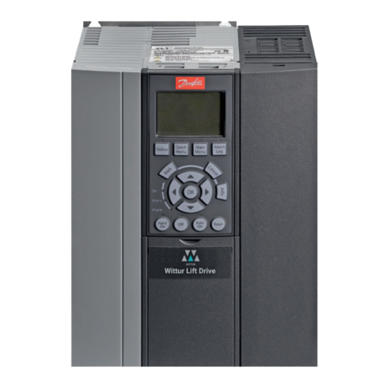
WITTUR LIFT DRIVE
No part of this publication may be reproduced
or translated, even in part, without prior written
permission from WITTUR.
Subject to change without notice!
www.wittur.com
Translation of the Original Operating Instructions
Download the Operating Instructions
Code
GM.8.004286.EN
Version
B
Date
24. Aug 2023
info.wed@wittur.com
www.wittur.com
© Copyright WITTUR 2023
Advertisement
Table of Contents

Subscribe to Our Youtube Channel
Related Manuals for WITTUR WLD 302


Summary of Contents for WITTUR WLD 302
- Page 1 Translation of the Original Operating Instructions Download the Operating Instructions No part of this publication may be reproduced info.wed@wittur.com or translated, even in part, without prior written www.wittur.com permission from WITTUR. © Copyright WITTUR 2023 Subject to change without notice! www.wittur.com...
-
Page 2: Table Of Contents
Commissioning ..................... 27 Motor and Encoder rotation direction ............27 Guideline for simple and fast setup ............28 Commissioning using Quick Menu ............29 Setup motor data for PM motor ............. 32 Wittur Lift Drive WLD 302, GM.8.004286.EN; Rev. 24. Aug 2023... - Page 3 Noise or vibrations during acceleration or deceleration (low frequency) ..66 Optimization ..................67 Troubleshooting .................... 69 Appendix...................... 70 Wiring Examples with Parameter setup ........... 70 Start and Stop Sequences ..............86 Drive Motor Database ................87 Wittur Lift Drive WLD 302, GM.8.004286.EN; Rev. 24. Aug 2023...
- Page 4 Quick Guide Wittur Lift Drive WLD302 Messages .................... 87 Warnings and Alarms ................87 10 EMC complaint installation ................98 11 Evacuation ....................100 Wittur Lift Drive WLD 302, GM.8.004286.EN; Rev. 24. Aug 2023...
-
Page 5: Introduction
Indicates a situation that may result in equipment or property-damage-only accidents. NODE Indicates highlighted information that should be regarded with attention to avoid mistakes or operate equipment at less than optimal performance. Wittur Lift Drive WLD 302, GM.8.004286.EN; Rev. 24. Aug 2023... -
Page 6: Safety
When the holding brake is included in a safety chain: The frequency converter cannot provide a safe control of a mechanical brake. A redundancy circuitry for the brake control must be included in the total installation. Wittur Lift Drive WLD 302, GM.8.004286.EN; Rev. 24. Aug 2023... -
Page 7: Crane, Lifts And Hoists
Check the motor characteristics for actual tolerances. • Ensure that the ingress protection rating of the frequency converter is suitable for the installation environment. IP55 (NEMA 12) or IP66 (NEMA 4) enclosures may be necessary. Wittur Lift Drive WLD 302, GM.8.004286.EN; Rev. 24. Aug 2023... -
Page 8: Ingress Protection
Mount the unit to a solid flat surface or to the optional back plate to provide cooling airflow. • Improper mounting can result in overheating and reduced performance. • Use the slotted mounting holes on the unit for wall mounting, when provided. Wittur Lift Drive WLD 302, GM.8.004286.EN; Rev. 24. Aug 2023... -
Page 9: Tightening Torques
All frequency converters must be provided with short-circuit and over-current protection. Input fusing is required to provide this protection, see Illustration. If not factory supplied, fuses must be provided by the installer as part of installation. Wittur Lift Drive WLD 302, GM.8.004286.EN; Rev. 24. Aug 2023... -
Page 10: Earth (Grounding)
• Earth ground wire of at least 10 mm². • Two separate earth ground wires both complying with the dimensioning rules. See EN 60364-5-54 § 543.7 for further information. Wittur Lift Drive WLD 302, GM.8.004286.EN; Rev. 24. Aug 2023... -
Page 11: Motor Connection
The following Illustration represents mains input, motor, and earth grounding for basic frequency converters. Actual configurations vary with unit types and optional equipment. Illustration: Example of Motor, Mains and Earth Wiring Wittur Lift Drive WLD 302, GM.8.004286.EN; Rev. 24. Aug 2023... -
Page 12: Back-Emf From Pm Motor
Equipment containing electrical components may not be disposed of together with domestic waste. It must be separately collected with electrical and electronic waste according to local and currently valid legislation. Wittur Lift Drive WLD 302, GM.8.004286.EN; Rev. 24. Aug 2023... -
Page 13: Schematic Drawing, Examples
Diagram showing all electrical terminals without options. A = analog, D = digital For instructions on Safe Stop installation please refer to the section Safe Stop Installation in the VLT® AutomationDrive FC 302 Design Guide. Wittur Lift Drive WLD 302, GM.8.004286.EN; Rev. 24. Aug 2023... - Page 14 Quick Guide Wittur Lift Drive WLD302 Schematic Lift Controller MCO 361 The numbers represent the terminals on the drive. VLT Lift Drive standard interfaces: • RS485 • USB • DCP 3/4 • CanOpen DSP 417 Wittur Lift Drive WLD 302, GM.8.004286.EN; Rev. 24. Aug 2023...
- Page 15 Item Description Item Description Terminal blocks, on the top 24 V/DC supply Terminal blocks, on the side Digital outputs Encoder Terminal Not used Can Terminal Digital Inputs Wittur Lift Drive WLD 302, GM.8.004286.EN; Rev. 24. Aug 2023...
-
Page 16: Encoder Connection
Clock /Clock Data /Data Example Endat 2.2 see Data Sheet Clock /Clock Data /Data Resolver- Option MCB 103 Resolver- Option MCB 103 Terminal- No. X32/ Description REF+ REF- COS+ COS- SIN+ SIN- Resolver Wittur Lift Drive WLD 302, GM.8.004286.EN; Rev. 24. Aug 2023... -
Page 17: Examples
[8] Output 128:1 [9] Output 256:1 [10] Output 512:1 [11] Output 1024:1 [12] Output 2048:1 [13] Output 4096:1 [14] Output 8192:1 3.15 Examples Operation with Motor Contactors K1 and K2 Wittur Lift Drive WLD 302, GM.8.004286.EN; Rev. 24. Aug 2023... - Page 18 Quick Guide Wittur Lift Drive WLD302 3.15.1 Operation without Motor Contactors Wittur Lift Drive WLD 302, GM.8.004286.EN; Rev. 24. Aug 2023...
-
Page 19: Programming
Display area C: Navigation keys for programming functions, moving the display cursor, and speed control in local operation. Also included are the status indicator lights. Display area D: Operation mode keys and reset. Wittur Lift Drive WLD 302, GM.8.004286.EN; Rev. 24. Aug 2023... - Page 20 Press and hold to enter a parameter number for direct access to a parameter. Alarm Log Displays a list of current warnings, the last 5 alarms, and the maintenance log. For details select the alarm number using the navigation keys and press [OK]. Wittur Lift Drive WLD 302, GM.8.004286.EN; Rev. 24. Aug 2023...
- Page 21 ALARM A fault condition causes the red alarm indicator lamp to flash and an alarm text is displayed. Wittur Lift Drive WLD 302, GM.8.004286.EN; Rev. 24. Aug 2023...
-
Page 22: Back Up And Copying Parameter Settings
Factory default parameter settings are restored during start-up. After powering-up the Lift Drive wait until the Lift application is loaded, and continue parameter setup, after the LCP displays “Operation Mode”. Wittur Lift Drive WLD 302, GM.8.004286.EN; Rev. 24. Aug 2023... -
Page 23: Main Menu
32-** MCO Basic Settings Setup Encoder, PID Controller 33-** MCO Adv. Settings Setup MCO- Terminal X60, CAN node, DCP3 / DCP4 34-** MCO Data Readouts MCO Display parameters for troubleshooting Wittur Lift Drive WLD 302, GM.8.004286.EN; Rev. 24. Aug 2023... -
Page 24: Parameter Overview
Vi, Inspection speed 0.300 19-24 V3, Intermediate speed 1 0.800 19-25 V2, Intermediate speed 2 0.300 19-26 Vn, Releveling speed 0.010 19-27 Floor level dist 19-28 V1, Intermediate speed 3 0.200 Wittur Lift Drive WLD 302, GM.8.004286.EN; Rev. 24. Aug 2023... - Page 25 Brake monitor delay 2.000 19-88 Fast Boot Mode 19-89 User Par 1989 19-90 SW- Version Version No. 19-92 Status Status No. 19-93 Dir change cnt 1 19-94 Dir change cnt 2 Wittur Lift Drive WLD 302, GM.8.004286.EN; Rev. 24. Aug 2023...
- Page 26 Digital Input [bin] 000000000000 Process Data 34-50 Actual Position 1mm/100 34-56 Track Error 1mm/100 34-59 Actual Velocity 1mm/100s * Getting the status of the input terminals of the control card: Wittur Lift Drive WLD 302, GM.8.004286.EN; Rev. 24. Aug 2023...
-
Page 27: Commissioning
The value in Parameter 16-06 decreases when the motor rotates counter- clockwise. If the encoder counter direction does not match to the direction of the motor, the counting direction of the encoder must be changed with: Swapping two encoder tracks Wittur Lift Drive WLD 302, GM.8.004286.EN; Rev. 24. Aug 2023... -
Page 28: Guideline For Simple And Fast Setup
8. Testrun (Inspection speed), check of basic operation and directions (chapter 6.1.1) 9. Activation of required monitoring functions 10. Optimization (chapter 6.2) 11. Wiring Examples with Parameter setup Wittur Lift Drive WLD 302, GM.8.004286.EN; Rev. 24. Aug 2023... -
Page 29: Commissioning Using Quick Menu
19-21, V4, nominal Speed [m/s] 19-77 19-66, Digital Serial (Control) 19-50, Run-in mode 19-86, Special Function 19-67, Function Relay 1 19-63, Motor adaptation (AMA) 19-03, Encoder Autotuning 19-05, Encoder direction 19-04, Car direction Wittur Lift Drive WLD 302, GM.8.004286.EN; Rev. 24. Aug 2023... - Page 30 The update procedure of the Quick Menu is necessary to refresh the Quick Menu with the right parameters depends on Motor number, Motor type and motor construction. Wittur Lift Drive WLD 302, GM.8.004286.EN; Rev. 24. Aug 2023...
- Page 31 See Automatic Motor Adaptation, P19-63. Furthermore, a voltage reserve for operation in field weakening can be entered in the P 1-54. 10 to 30 V are recommended here. Wittur Lift Drive WLD 302, GM.8.004286.EN; Rev. 24. Aug 2023...
-
Page 32: Setup Motor Data For Pm Motor
For Lift application with motor feedback, it is necessary to setup the encoder data. Name Parameter Description 32-00 Incremental Signal Type [0] None (for induction motors open loop) [1] RS-422 (5V TTL) [2] Sinusoidal 1Vpp 32-01 Incremental Resolution Pulses per revolution Wittur Lift Drive WLD 302, GM.8.004286.EN; Rev. 24. Aug 2023... -
Page 33: Setup Mechanical Data
[3] CanOpen DSP417 Power cycle drive after change of control type 5.10 Setup control type Name Parameter Description 19-50 Run-in mode Set mode due to desired control type as described Wittur Lift Drive WLD 302, GM.8.004286.EN; Rev. 24. Aug 2023... -
Page 34: Setup Special Functions
[1] VLT-Ready [2] Short circuit relay [3] Motor Contactors (as X59.4) [4] Ready signal (as X59.5) [5] Short circuit relay (standstill) [6] Speed V > 0,2 m/s [7] Start enabled Wittur Lift Drive WLD 302, GM.8.004286.EN; Rev. 24. Aug 2023... -
Page 35: Functional Descriptions
2. The elevator should run now at least three times with nominal speed in normal operation. 3. The AMA procedure is finished when the LCP status display changes from “P19-63 [4]” back to the status display “P19-63 [0]” Wittur Lift Drive WLD 302, GM.8.004286.EN; Rev. 24. Aug 2023... - Page 36 Data sheets for motors usually also contain information on the back EMF based on the nominal motor speed. The back EMF referred to 1000 rpm can be calculated as follows. Example: Back EMF 320V at 1800 RPM. Back EMF=(320V/1800)*1000=178V Wittur Lift Drive WLD 302, GM.8.004286.EN; Rev. 24. Aug 2023...
-
Page 37: Mechanical Brake Control
Brake close Motor off In- Position Parameter Description 19-13 Brake Lift delay 19-14 Brake delay 19-19 Run in distance 19-58 Delay after Stop 19-15 Brake close delay 19-59 Torque down time Wittur Lift Drive WLD 302, GM.8.004286.EN; Rev. 24. Aug 2023... -
Page 38: Control Of The Mechanical Brake With Sbu 2.0
19-77 Shaft encoder node-id 19-77 Number of brakes (1 to 3) 19-77 Shaft encoder - Resolution (number of pulses) 19-77 Shaft encoder – Path of resolution impulses 19-77 SBU SW-Version Wittur Lift Drive WLD 302, GM.8.004286.EN; Rev. 24. Aug 2023... - Page 39 The error memory, Par. 19-81 displays 516. • It must not be possible to start the lift (EN81-20 5.9.3.4.4) • Switch off the test mode of the SBU. Par.19-77 = 0 • Wittur Lift Drive WLD 302, GM.8.004286.EN; Rev. 24. Aug 2023...
- Page 40 In case the system is designed according to the example, the simple control mode needs to activated in P 19-86. Wittur Lift Drive WLD 302, GM.8.004286.EN; Rev. 24. Aug 2023...
-
Page 41: Speeds, Acceleration, Jerks
Decel. Jerk [mm/s³] 19-35 Run in Jerk [mm/s³] 19-55 L-start acc [mm/s²] Linear start function deactivated when L-start time is 19-56 L-start speed [mm/s] set to 0 19-57 L-start time [ms] Wittur Lift Drive WLD 302, GM.8.004286.EN; Rev. 24. Aug 2023... - Page 42 During inspection, the small speed Vi should always be selected, and if a higher speed is necessary, the faster speed V1 should be used. (fast, slow) This allows the switching between the speeds. Wittur Lift Drive WLD 302, GM.8.004286.EN; Rev. 24. Aug 2023...
-
Page 43: Deceleration Distance
Filter time of the speed controller, can be 4.0-10.0 start [ms] used to filter out vibrations from the system or disturbances of the encoder- signal 19-46 Pos. gain Position controller gain during start 0.2 - 0.5 start Wittur Lift Drive WLD 302, GM.8.004286.EN; Rev. 24. Aug 2023... -
Page 44: Control Sources P19-66
Lift controller. Use Lift drive setup tool for logging. 1974 BUS STAT Display parameter for DCP status byte and extended status to Lift controller. Use Lift drive setup tool for logging. Wittur Lift Drive WLD 302, GM.8.004286.EN; Rev. 24. Aug 2023... - Page 45 CAN Open specification is required. (120 Ohm between CAN-H and CAN-L) The terminal strip X62 is located at the upper right on the casing. The connections are exposed by breaking out the designated windows. Wittur Lift Drive WLD 302, GM.8.004286.EN; Rev. 24. Aug 2023...
- Page 46 Power cycle the drive after change of control type. Data readouts Name Parameter Description 19-73 BUS CMD Display parameter for DSP command byte 1974 BUS STAT Display parameter for DSP status byte Wittur Lift Drive WLD 302, GM.8.004286.EN; Rev. 24. Aug 2023...
-
Page 47: Position Mode
P19-69 are entered. The values must be within 1 +/- 5%. If exceeded, error 225 is generated. Verify system data in case of deviations. Only when P19-72 is aligned with 19-69, an optimal approach to floor level is possible. Wittur Lift Drive WLD 302, GM.8.004286.EN; Rev. 24. Aug 2023... -
Page 48: Operation With Absolute Encoder (Ssi/Endat/Biss-C)
Display of the rotor position determined by the absolute encoder after power on. If P19-09 = -1, the rotor position display is continuously updated. The value is updated after power is turned on. Wittur Lift Drive WLD 302, GM.8.004286.EN; Rev. 24. Aug 2023... -
Page 49: Operation With Ups, Evacuation Mode
If a UPS with reduced power is used for evacuation, this must be communicated to the frequency converter via a signal at input X57.8 or via serial communication. In UPS mode, the speed is always limited to the evacuation speed (P19-22). Wittur Lift Drive WLD 302, GM.8.004286.EN; Rev. 24. Aug 2023... -
Page 50: Operation Vvc+ Open Loop For Induction Motors
[1x] Short Floor function, short stop journey [2x] USV-Operation, Evacuation in load direction Only used for open loop applications (without encoder), with closed loop (with encoder) the setting has no function. [3x] SF and USV Wittur Lift Drive WLD 302, GM.8.004286.EN; Rev. 24. Aug 2023... - Page 51 A overshoot will be prevented as well as long slow speed duration. The short floor function is only available for nominal speed v4. Wittur Lift Drive WLD 302, GM.8.004286.EN; Rev. 24. Aug 2023...
- Page 52 UPS operation in load direction If this function is activated, the drive will operate the elevator in load direction, independent on the given direction control signals, in case of activated UPS input. Wittur Lift Drive WLD 302, GM.8.004286.EN; Rev. 24. Aug 2023...
-
Page 53: Use Of Terminals T27 And X57.1
(NC). System with relays or contactors for the motor, optionally with STO and • optionally with a short-circuit circuit for the motor winding (NC). optional. KK= short-circuit relay Wittur Lift Drive WLD 302, GM.8.004286.EN; Rev. 24. Aug 2023... - Page 54 X59.3, Control Speed 2 X59.4, Output contactor X59.5, Ready Signal X59.6, Over Temperature X59.7, Standstill Position reached 19-85 Load direction [-1] Load direction down (full cabin) [1] Load direction up (empty cabin) Wittur Lift Drive WLD 302, GM.8.004286.EN; Rev. 24. Aug 2023...
-
Page 55: Monitoring Functionalities
[2xx] Safe Stop (STO) monitoring, terminal 37. [3xx] Contactor monitoring and Safe Stop (STO), terminal 27, terminal X57.1, and terminal 37. [3xx] Contactor monitoring and Safe Stop (STO), terminal 27, terminal X57.1, and terminal 37. Wittur Lift Drive WLD 302, GM.8.004286.EN; Rev. 24. Aug 2023... - Page 56 The monitoring due to DIN EN 81-20 is only available if in parameter 19-90 the identifier A3 is displayed. e.g. S_A3_B_X.XXT/RXXX. Illustration: Schematic drawing Brake Monitor with N.O. contacts, P 19-65 = [x1] Wittur Lift Drive WLD 302, GM.8.004286.EN; Rev. 24. Aug 2023...
- Page 57 The interlock stays active even in the case of a loss of power supply, unless a reset is done by setting P19-64 to the value -1 or by pressing the LCP-keys [Back] + [Reset] simultaneously. NOTE: For reset of critical errors see chapter Reset locked error. Wittur Lift Drive WLD 302, GM.8.004286.EN; Rev. 24. Aug 2023...
- Page 58 Depending on the cause one of the following failures will be created: - 251 CO1_T27 off, - 252 CO2_X57/1 of Wittur Lift Drive WLD 302, GM.8.004286.EN; Rev. 24. Aug 2023...
-
Page 59: Standby Function
Standby function can be activated with input terminal 19 or by DCP telegram. If digital inputs are used to control the drive the standby function cannot be combined with the governor monitoring function. Wittur Lift Drive WLD 302, GM.8.004286.EN; Rev. 24. Aug 2023... -
Page 60: Test Run Mode
This function is only allowed for start direction Up. The function will be disabled automatically after the cabin has moved 100mm or after stopping the drive by control signal. Wittur Lift Drive WLD 302, GM.8.004286.EN; Rev. 24. Aug 2023... -
Page 61: Direction Change Counter
P19-94 has a value range from 0 to 2147483646. After reaching the maximum value, the counter starts again at zero. The change of direction counter 2 can be preset in the range from 1 to 16,000,000 using parameters 19-71. Wittur Lift Drive WLD 302, GM.8.004286.EN; Rev. 24. Aug 2023... - Page 62 From the activation of direction change counter 1, digital output 59.2 only outputs the counter warning. If the counter is deactivated (by factory setting), X 59.2 outputs a speed-dependent value. Wittur Lift Drive WLD 302, GM.8.004286.EN; Rev. 24. Aug 2023...
-
Page 63: Alarm Log
P19-64= -1 or by simultaneously pressing the [Back]+[Reset] keys. NOTICE: Reset of critical errors, message "Drive locked" with parameter P19-64 --> [-1]. may only be reset by trained specialists. Wittur Lift Drive WLD 302, GM.8.004286.EN; Rev. 24. Aug 2023... -
Page 64: Short Circuit Function
3. Short circuit at standstill a. The short circuit is activated at every standstill. For Relay 1, see Parameter 19-67 [5] Short circuit contactor at standstill. c. • For digital outputs, see Parameter 19-84 (5) Short circuit contactor at standstill. Wittur Lift Drive WLD 302, GM.8.004286.EN; Rev. 24. Aug 2023... -
Page 65: Operation
[-1] absolute encoder value will be displayed in P19-98. No movement of the drive possible [0-8192] Encoder Offset 19-98 Abs. enc. position Shows the value of the absolute encoder. Value is updated after power up Wittur Lift Drive WLD 302, GM.8.004286.EN; Rev. 24. Aug 2023... -
Page 66: Start-Error Or Track-Error Or Accelerates Unexpected Or Does Not Move
(Minimum 20). Motors without any load can only be run with the minimum value of 20 in P19-41. Name Parameter Description 19-41 KP-Gain at Proportional part of the speed controller. Decrease the operation value when motor generates noise or vibration. Wittur Lift Drive WLD 302, GM.8.004286.EN; Rev. 24. Aug 2023... -
Page 67: Optimization
Value needed for Gearless motor 0.2-0.5 0.0-0.4 start Controller behavior during operation In case of overshoot at the end of acceleration or deceleration, a decreased I time P19-42 can optimize this behavior. Wittur Lift Drive WLD 302, GM.8.004286.EN; Rev. 24. Aug 2023... - Page 68 The brake is closed, and the torque is reduced to 0Nm within the ramp time; afterward, the motor is turned off. Affects the mechanical noise of the brake when the motor is off. Wittur Lift Drive WLD 302, GM.8.004286.EN; Rev. 24. Aug 2023...
-
Page 69: Troubleshooting
Sporadic A38 during operation Check the EMC-compliant installation of motor and control cables. Pay special attention to extensive shield connections and sufficient grounding of components and system parts. See Chapter 10 Wittur Lift Drive WLD 302, GM.8.004286.EN; Rev. 24. Aug 2023... -
Page 70: Appendix
Example 1: Mode 0, Digital speed selection, low speed priority, direction priority up Configuration: Motor contactors controlled by drive Speeds: 6 Priority: slow speed, inspection, relevelling, intermed.2, intermed.1, high speed Start Signal: Start with direction signal Wittur Lift Drive WLD 302, GM.8.004286.EN; Rev. 24. Aug 2023... - Page 71 Example 2: Mode 0, Digital speed selection, low speed priority, direction priority up Configuration: Motor contactors controlled by drive, Output X59.4 Speeds: 6 Priority: slow speed, inspection, relevelling, intermed.2, intermed 1, high speed Start Signal: Start with direction signal Wittur Lift Drive WLD 302, GM.8.004286.EN; Rev. 24. Aug 2023...
- Page 72 Configuration: Without motor contactors, only 24V control signals to lift controller used Speeds: 6 Priority: slow speed, inspection, relevelling, intermed.2, intermed 1, high speed Start with enable signal from lift controller, safety relays controlled by lift Start Signal: controller Wittur Lift Drive WLD 302, GM.8.004286.EN; Rev. 24. Aug 2023...
- Page 73 Example 4: Mode 0, Digital speed selection, low speed priority, direction priority up Configuration: Without motor contactors Speeds: 6 Priority: slow speed, inspection, relevelling, intermed.2, intermed.1, high speed Start Signal: Start with direction signal Wittur Lift Drive WLD 302, GM.8.004286.EN; Rev. 24. Aug 2023...
- Page 74 Example 5: Mode 1, Digital speed selection, high speed priority, direction priority up- Configuration: Motor contactors controlled by drive Speeds: 6 Priority: slow speed, inspection, relevelling, intermed.2, intermed.1, high speed Start Signal: Start with direction signal Wittur Lift Drive WLD 302, GM.8.004286.EN; Rev. 24. Aug 2023...
- Page 75 Mode 1, slow speed direction Example 6: Mode 1, slow speed with direction signal Configuration: Motor contactors controlled by drive Speeds: 3 Priority: slow speed, inspection, high speed Start Signal: Start with direction signal Wittur Lift Drive WLD 302, GM.8.004286.EN; Rev. 24. Aug 2023...
- Page 76 Example 7: Mode 4, Binary speed selection 1, direction priority up Configuration: Motor contactors controlled by drive Speeds: 6 Slow speed, inspection, relevelling, intermed.3, intermed.2, intermed 1, high speed Start Signal: Start with direction signal Wittur Lift Drive WLD 302, GM.8.004286.EN; Rev. 24. Aug 2023...
- Page 77 Example 8: Mode 6, Binary speed selection 2, direction priority up Configuration: Motor contactors controlled by drive Speeds: 7 Slow speed, inspection, relevelling, intermed.3, intermed.2, intermed.1, high speed Start Signal: Start with direction signal Wittur Lift Drive WLD 302, GM.8.004286.EN; Rev. 24. Aug 2023...
- Page 78 Example 9: Mode 7, Digital speed selection, low speed priority, direction priority down Configuration: Motor contactors controlled by drive Speeds: 6 Priority: slow speed, inspection, relevelling, intermed.2, intermed.1, high speed Start Signal: Start with direction signal Wittur Lift Drive WLD 302, GM.8.004286.EN; Rev. 24. Aug 2023...
- Page 79 Example 10: Mode 8, HTL-encoder, digital speed selection 1, direction priority up Configuration: Motor contactors controlled by drive Speeds: 4 Slow speed, inspection, intermed 1, high speed Start Signal: Start with direction signal Wittur Lift Drive WLD 302, GM.8.004286.EN; Rev. 24. Aug 2023...
- Page 80 Example 11: Mode 9, HTL-encoder, Binary speed selection, direction priority up Configuration: Motor contactors controlled by drive Speeds: 4 Slow speed, inspection, intermed 1, high speed Start Signal: Start with direction signal Wittur Lift Drive WLD 302, GM.8.004286.EN; Rev. 24. Aug 2023...
- Page 81 Quick Guide Wittur Lift Drive WLD302 Bus controlled /DCP3/DCP4 Example 12: Bus controlled /DCP3/DCP4 Configuration: Without motor contactors Start Signal: Bus controlled, Hardware enable signal from lift controller Wittur Lift Drive WLD 302, GM.8.004286.EN; Rev. 24. Aug 2023...
- Page 82 Quick Guide Wittur Lift Drive WLD302 Monitoring of motor contactors Example 13: Monitoring of motor contactors Configuration: Start with direction signal Wittur Lift Drive WLD 302, GM.8.004286.EN; Rev. 24. Aug 2023...
- Page 83 Quick Guide Wittur Lift Drive WLD302 Monitoring of motor contactors Example 14: Monitoring of motor contactors Configuration: Start with enable signal Wittur Lift Drive WLD 302, GM.8.004286.EN; Rev. 24. Aug 2023...
- Page 84 Quick Guide Wittur Lift Drive WLD302 Monitoring brake feedback 1, normal open contacts Example 15: Monitoring of brake feedback 1, normal open contacts Configuration: Start with direction signal Wittur Lift Drive WLD 302, GM.8.004286.EN; Rev. 24. Aug 2023...
- Page 85 Quick Guide Wittur Lift Drive WLD302 Monitoring brake feedback 2, normal closed contacts Example 16: Monitoring of brake feedback 2, normal closed contacts Configuration: Start with direction signal Wittur Lift Drive WLD 302, GM.8.004286.EN; Rev. 24. Aug 2023...
-
Page 86: Start And Stop Sequences
Quick Guide Wittur Lift Drive WLD302 9.2 Start and Stop Sequences Illustration 4.1 Lift Control Start Sequence in operating mode Illustration 4.2 Lift Control Stop Sequence in operating mode Wittur Lift Drive WLD 302, GM.8.004286.EN; Rev. 24. Aug 2023... -
Page 87: Drive Motor Database
If the intermediate circuit voltage (DC link) drops below the under-voltage limit, the frequency converter checks if a 24 V DC back-up supply is connected. If no 24 V DC backup supply is Wittur Lift Drive WLD 302, GM.8.004286.EN; Rev. 24. Aug 2023... - Page 88 If extended mechanical brake control is selected, trip can be reset externally. Troubleshooting Remove power and check if the motor shaft can be turned. Check that the motor size matches the Wittur Lift Drive WLD 302, GM.8.004286.EN; Rev. 24. Aug 2023...
- Page 89 If [2] Trip is selected in 2-13 Brake Power Monitoring, the frequency converter trips when the dissipated braking power reaches 100%. WARNING If the brake transistor is short-circuited there is a Wittur Lift Drive WLD 302, GM.8.004286.EN; Rev. 24. Aug 2023...
- Page 90 ALARM 68, Safe Stop activated Safe Torque Off has been activated. To resume normal operation, apply 24 V DC to terminal 37, then send a reset signal (via Bus, Digital I/O, or by pressing [Reset]. Wittur Lift Drive WLD 302, GM.8.004286.EN; Rev. 24. Aug 2023...
- Page 91 Warning limit of direction change counter counter low exceeded Direction change TRIP Direction change counter exceeded, speed reduced counter expired to v0 and vi Encoder error SSI TRIP Encoder error SSI-absolute encoder Wittur Lift Drive WLD 302, GM.8.004286.EN; Rev. 24. Aug 2023...
- Page 92 STO Signal on T37 not changed to LOW before start VLT-Alarm of control TRIP VLT-Alarm of control card. See alarm log of control card. See alarm log of card control card Wittur Lift Drive WLD 302, GM.8.004286.EN; Rev. 24. Aug 2023...
- Page 93 50 (+10 V supply). Also check that the terminal switch for 53 or 54 is set for voltage. Check that 1-93 Thermistor Source selects terminal 53 or 54. When using Wittur Lift Drive WLD 302, GM.8.004286.EN; Rev. 24. Aug 2023...
- Page 94 Troubleshooting Check for the following conditions. • Ambient temperature too high. • Motor cable too long. Incorrect airflow clearance above and below the frequency converter. • Wittur Lift Drive WLD 302, GM.8.004286.EN; Rev. 24. Aug 2023...
- Page 95 ALARM 52, AMA low Inom The motor current is too low. Check the settings. ALARM 53, AMA motor too big The motor is too big for the AMA to operate. Wittur Lift Drive WLD 302, GM.8.004286.EN; Rev. 24. Aug 2023...
- Page 96 The control card and power card are incompatible. To check compatibility, contact your supplier with the type code of the unit from the nameplate and the part numbers of the cards. Wittur Lift Drive WLD 302, GM.8.004286.EN; Rev. 24. Aug 2023...
- Page 97 ALARM 80, Drive initialized to default value Parameter settings are initialized to default settings after a manual reset. To clear the alarm, reset the unit. Wittur Lift Drive WLD 302, GM.8.004286.EN; Rev. 24. Aug 2023...
-
Page 98: Emc Complaint Installation
Lift controller terminal box Potential compensation rail Main power cable Control cables Lift controller Brake resistor cable Encoder cable Mech. Brake cable Motor cable Earth and ground cable min. 16 mm² Detailed view: Wittur Lift Drive WLD 302, GM.8.004286.EN; Rev. 24. Aug 2023... - Page 99 Quick Guide Wittur Lift Drive WLD302 Note: Wittur Lift Drive WLD 302, GM.8.004286.EN; Rev. 24. Aug 2023...
-
Page 100: Evacuation
Quick Guide Wittur Lift Drive WLD302 11 Evacuation Schematic diagram evacuation Wittur Lift Drive WLD 302, GM.8.004286.EN; Rev. 24. Aug 2023... - Page 101 YOUR GLOBAL PARTNER FOR COMPONENTS, MODULES AND SYSTEMS IN THE ELEVATOR INDUSTRY...
Need help?
Do you have a question about the WLD 302 and is the answer not in the manual?
Questions and answers