
Related Manuals for Speck pumps 1.1 THP Dual Voltage Series


Summary of Contents for Speck pumps 1.1 THP Dual Voltage Series
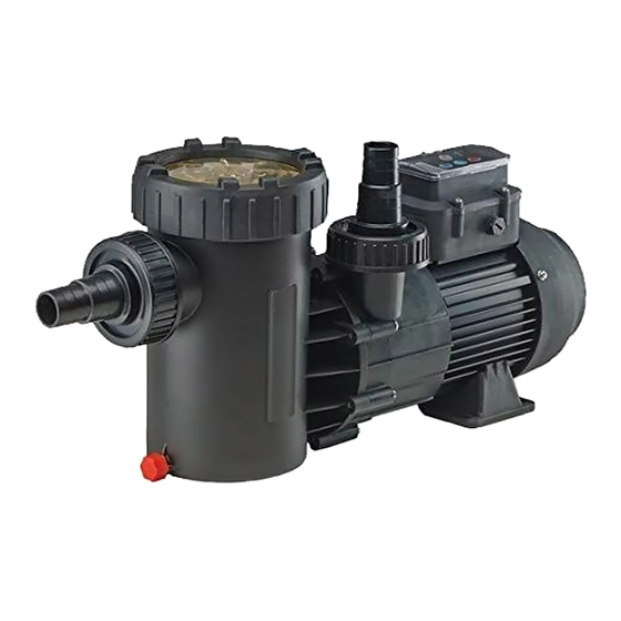
- Page 1 Installation, Operation, and Service Manual Dual Voltage Series Variable Speed Pool Pump Motor Version 2.0 02/2019...
- Page 2 904-739-2626 Fax: 904-737-5261 Website: www.usa.speck-pumps.com Email: technical.usa@speck-pumps.com Manufactured by Speck Pumps, Jacksonville Florida USA, ©2019 All Rights Reserved. This document is subject to change without notice. Date of Installation: Installed by: Serial Number: For Service Call: 2999999406 - Rev. 0419...
-
Page 3: Table Of Contents
Table of Contents Important Safety Instructions SwimJet Combination Fitting Manufacturers Warnings. . 4 General Safety Instructions....5 General Description Installation Information Preparation Guide ....7 Pump Location . -
Page 4: Important Safety Instructions
Important Safety Instructions WARNING: Before Installing this product, read and follow all warning notices and instructions which are included. Failure to follow safety warnings and instructions can result in severe injury, death, or property damage. Call (800) 223-8538 or visit www.usa.speck-pumps.com for additional copies of these instructions. Important Notice: This manual contains important information about the installation, operation and safe use of this product. -
Page 5: General Safety Instructions
General Safety Instructions The following guidelines provide information to minimize the risk of injury to users of pools, spas, and hot tubs. WARNING: TO REDUCE THE RISK OF ENTRAPMENT HAZARD Pool and spa pumps produce high levels of suction, which can pose extreme danger if a person comes in close proximity to an open pool or spa drain or if a drain cover is loose, cracked, broken or missing. -
Page 6: General Description
General Safety Instructions - continued WARNING - Risk of Electrical Shock or Electrocution Pool pump must be installed by a licensed or certified electrician or a qualified pool serviceman in accordance with the National Electrical Code and all applicable local codes and ordinances. Improper installation will create an electric hazard which could result in death or serious injury to pool users, installers, or others due to electrical shock, and may also cause damage to property. -
Page 7: Installation Information
Installation Information Preparation Guide 1. Upon receipt of the pump, check the carton for damage. Open the carton and check the pump for concealed damage, such as cracks, dents, or a broken base. If damage is found, contact the shipper or distributor where the pump was purchased. 2. -
Page 8: Plumbing Installation
Plumbing Installation 1. When connecting pipework to pump with threaded ports, it is recommended that thread seal tape be used. Hard-plumbed pipes must have proper solvent-weld connections. Flexible hose connections must be tightened properly. If the suction line is not sealed correctly, the pump will not prime properly and will pump small volumes of water or none at all. 2. -
Page 9: Voltage Checks
Electrical Installation - continued 3. Insulate all connections carefully to prevent grounding or short-circuits. Sharp edges on terminals require extra protection. To prevent the wire nuts from loosening, tape them using suitable, listed (UL, ETL, CSA) electrical insulating tape. For safety, and to prevent entry of contaminants, reinstall all conduit and terminal box covers. -
Page 10: Operation
Pressure Test - continued STEPS: 1. Fill the system with water, using care to eliminate trapped air. 2. Pressurize the system with water to no more than 35 PSI. WARNING: DO NOT pressure test above 35 PSI. Pressure testing must be done by a trained pool professional. Circulation equipment that is not tested properly might fail, which would result in severe injury or property damage. -
Page 11: Enter Programming Mode
Start Up Guide - continued Prime Sequence: If full prime has not been achieved after prime cycle (max. 10 minutes), press the “0” button to stop the pump. Refill the pump with water and restart. Allow the pump to run for up to 10 minutes to allow air trapped in the suction line to be purged. -
Page 12: Schedule (Sche) Menu
Schedule (SCHE) Menu 1. Enter programing mode by pressing and holding the button for at least three (3) seconds when the pump is in the stopped (OFF) position. Once SCHE begins flashing on the LED display, press the button. 2. After entering the schedule menu, S1 (speed/power level setting 1) flashes on the LED display. Use the buttons ... -
Page 13: Override (Ovrd) Menu
Override (OVRD) Menu 1. Enter programing mode by pressing and holding the button for at least three (3) seconds when the pump is in the stopped (OFF) position. 2. Use the buttons to select OVRD. See Figure 8. Press the button to enter the override menu. -
Page 14: Normal Operation
Priming (PR) Menu - Continued 4. The priming time now flashes on the LED display. The factory default setting is two (2) minutes. Use the buttons to select the desired priming time between zero (0) and ten (10) minutes, in 1-minute increments. Press the button to save and exit the priming and programming menus. -
Page 15: User Interface Lockout
Normal Operation - continued To stop the pump at any time, press the “0” button. The pump will come to a stop and the LED display will read OFF. NOTE: If the power is shut off or the pump is stopped using the “0” button, upon restart the pump will run through the programmed priming cycle and then resume normal operation. -
Page 16: Winterizing
Routine Maintenance - continued 8. Verify that all valves have been returned to the proper position for normal operation. Turn ON the power to the pump. NOTE: It is normal for a few drops of water to escape from the mechanical seal from time to time. This is especially true during the break-in period. -
Page 17: Troubleshooting
Troubleshooting Controller Errors WARNING: The pump must be serviced by a professional service technician qualified in pool/spa installation. The following procedures must be followed exactly. Improper installation and/or operation can create dangerous electrical hazards, which can cause high voltage to run through the electrical system. This can cause property damage, serious personal injury, and/ or death. -
Page 18: General Pump Troubleshooting
General Pump Troubleshooting Table 3.0 Problem Possible Cause Solution 1. Pump will not prime. A. Suction air leak Make sure see-through lid and o-rings are clean and properly positioned. Hand tighten see- through lid. Tighten all pipes and fittings on suction side of pump. - Page 19 Removal and Replacement of the Impeller and/or Mechanical Seal 2. Turn OFF any valves to prevent pool water from reaching the pump. Drain water from the pump by loosening the unions or removing the drain plugs. 3. Remove the eight (8) screws connecting the pump casing/strainer tank to the flange. 4.
-
Page 20: Motor Replacement
Motor Replacement WARNING: The pump must serviced by a professional service technician qualified in pool/spa installation. The following procedures must be followed exactly. Improper installation and/or operation can create dangerous electrical hazards, which can cause high voltage to run through the electrical system. This can cause property damage, serious personal injury, and/ or death. -
Page 21: Product Specification
Product Specifications Dimensional Drawings & Performance Curves Model A91-II VSP 21.7” 10.1” 1000 Watts (3350-3500 RPM) 0.4” 0.3” 13.2” 5.1” 13.6” 6.3” 100 Watts 7.8” 450 Watts (1450-1700 RPM) (2550-3000 RPM) U.S. Gallons Per Minute Model E71-II VHV 24.2” 12.9” 1000 Watts (3000-3500 RPM) 1.1”... -
Page 22: Replacement Parts And Exploded View
Replacement Parts and Exploded View Model ES90 Drawing Order # Number Required Description 2901116010 LID - CLEAR 2901116010B NOT SHOWN LID - CLEAR with LED LIGHT 2921116022 LOCK RING WITH HANDLES - LID 2921141210 O-RING - LID 137 x 5mm 2901114300 BASKET - ONE PIECE 2921110130... - Page 23 Replacement Parts and Exploded View - continued Model A91 Drawing Order # Number Required Description 2901316020 LOCK RING - LID 2901316010 LID - CLEAR 2901341220 O-RING - LID 105 x 5mm 2500300912 4, 5, 5.1 & 5.2 COMPLETE UNION PACKAGE - SUCTION/DISCHARGE - SLIP/HOSE 2500300915 4, 5, &...
- Page 24 Replacement Parts and Exploded View - continued Model E71 Drawing Order # Number Required Description 2901116020 LOCK RING - LID 2901116010 LID - CLEAR 2901141201 O-RING - LID 137 x 5mm 2901114300 BASKET - ONE PIECE 2901141200 O-RING - CASING 144 x 4mm 2921923193 IMPELLER (-II) 1.1THP 106/9mm W/INSERT 2991000091...
-
Page 25: Limited Warranty
2. To the fullest extent permitted by law, the Limited Warranty will be void and of no force or effect and Speck Pumps - Pool Products, Inc. will have no liability, responsibilities or obligations to Buyer or with respect to the pump and motor in the event of the occurrence of any... - Page 26 Limited Warranty Period. Speck Pumps - Pool Products, Inc. shall not bear any costs or risks incurred by Buyer in shipping a defective pump and motor to Speck Pumps - Pool Products, Inc. or in shipping a repaired or replaced...
- Page 28 2999999406 - Rev 0717...
Need help?
Do you have a question about the 1.1 THP Dual Voltage Series and is the answer not in the manual?
Questions and answers