Table of Contents
Advertisement
Quick Links
Advertisement
Table of Contents

Subscribe to Our Youtube Channel
Related Manuals for Trenz Electronic TE0712 TRM


Summary of Contents for Trenz Electronic TE0712 TRM
- Page 1 TE0712 TRM Revision: Date: 07-Jun-2017 19:08...
-
Page 2: Table Of Contents
Document Change History ____________________________________________________________ 18 Disclaimer ___________________________________________________________________________ 19 Document Warranty __________________________________________________________________ 19 Limitation of Liability _________________________________________________________________ 19 Copyright Notice ____________________________________________________________________ 19 Technology Licenses _________________________________________________________________ 19 Environmental Protection _____________________________________________________________ 19 REACH, RoHS and WEEE ____________________________________________________________ 20 Copyright © 2017 Trenz Electronic GmbH Page http://www.trenz-electronic.de... -
Page 3: Overview
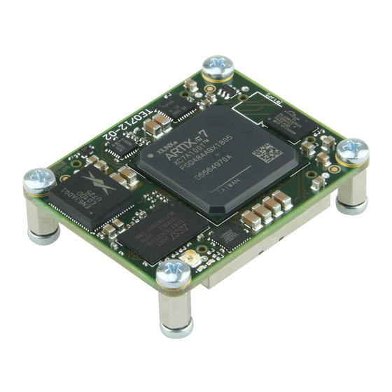
Numerous configurable I /Os are provided via rugged high-speed strips. All this on a tiny footprint, smaller than a credit card size at very competitive price. All Trenz Electronic SoMs in 4 x 5 cm form factor are mechanically compatible. Key Features... -
Page 4: Block Diagram
TE0712 TRM Revision: V14 Block Diagram Copyright © 2017 Trenz Electronic GmbH Page http://www.trenz-electronic.de... -
Page 5: Main Components
Xilinx Artix-7 FPGA Not programmed System Controller CPLD Programmed SPI Flash OTP area Empty SPI Flash main array Empty SPI Flash Quad Enable bit Microchip 11AA02E48 Globally unique EUI-48 (Ethernet MAC address) Copyright © 2017 Trenz Electronic GmbH Page http://www.trenz-electronic.de... -
Page 6: Signals, Interfaces And Pins
B2B Pin JM2-93 JM2-95 JM2-97 JM2-99 JTAGEN pin in B2B connector JM1 is used to select JTAG access for FPGA or SC CPLD: JTAGEN JTAG Access To Artix-7 FPGA High System Controller CPLD Copyright © 2017 Trenz Electronic GmbH Page http://www.trenz-electronic.de... -
Page 7: System Controller I/O Pins
Color SC Signal SC Pin Notes Green SYSLED1 Exact function depends on System Controller CPLD firmware. SYSLED2 Exact function depends on System Controller CPLD firmware. Copyright © 2017 Trenz Electronic GmbH Page http://www.trenz-electronic.de... -
Page 8: Clocking
PLL_CLK_P/N 50 MHz Certain B2B connector pins are connected to the FPGA pins which are capable of handling clocking signals from the user’s PCB (baseboard). See schematics B2B page for additional information. Copyright © 2017 Trenz Electronic GmbH Page http://www.trenz-electronic.de... -
Page 9: On-Board Peripherals
Memory speed: limited by Xilinx Artix-7 speed grade and MIG Configuration of the DDR3 memory controller in the FPGA should be done using the MIG tool in the Xilinx Vivado Design Suite IP catalog. Copyright © 2017 Trenz Electronic GmbH Page http://www.trenz-electronic.de... -
Page 10: Ethernet Phy
The bus is controlled by a master device (Xilinx Artix-7) which determines the clock period, controls the bus access and initiates all operations, while the SEEPROM works as a slave. Refer to Microchip's 11AA02E48 datasheet for more information. Copyright © 2017 Trenz Electronic GmbH Page http://www.trenz-electronic.de... -
Page 11: Power And Power-On Sequence
See Xilinx datasheet DS181 - "Artix-7 FPGAs Data Sheet: DC and AC Switching Characteristics" for additional information. User should also check related baseboard documentation when choosing baseboard design for TE0712 module. Copyright © 2017 Trenz Electronic GmbH Page http://www.trenz-electronic.de... -
Page 12: Power Rails
High-Range bank supply voltage (from the baseboard). VCCIO15 7, 9 Input High-Range bank supply voltage (from the baseboard). VCCIO16 9, 11 Input High-Range bank supply voltage (from the baseboard). VREF_JTAG Output JTAG reference voltage (3.3V). Copyright © 2017 Trenz Electronic GmbH Page http://www.trenz-electronic.de... -
Page 13: Board To Board Connectors
These connectors are hermaphroditic. Odd pin numbers on the module are connected to even pin numbers on the baseboard and vice versa. Trenz Electronic 4 x 5 modules use two or three Samtec Razor Beam™ LSHM connectors on the bottom side. -
Page 14: Manufacturer Documentation
Version Date LSHM-1XX-XX.X-X-DV-A-X-X-TR-FOOTPRINT(1).pdf 2013-11-28 16:54 LSHM-1XX-XX.X-XX-DV-A-X-X-TR-MKT.pdf 2013-11-28 16:56 REF-189016-01.pdf 2015-10-30 11:54 REF-189016-02.pdf 2015-10-30 11:54 REF-189017-01.pdf 2015-10-30 11:54 REF-189017-02.pdf 2015-10-30 11:54 TC0923--2523_report_Rev_2_qua.pdf 2013-11-28 16:55 hsc-report_lshm-lshm-05mm_web.pdf 2013-11-28 16:56 lshm_dv.pdf 2013-11-28 16:56 tc0929--2611_qua(1).pdf 2013-11-28 16:55 Copyright © 2017 Trenz Electronic GmbH Page http://www.trenz-electronic.de... -
Page 15: Variants Currently In Production
0°C to 85°C Commercial grade 4.0 mm TE0712-02-100-2C3 XC7A100T-2FGG484C 0°C to 85°C Commercial grade 2.5 mm TE0712-02-200-2C XC7A200T-2FBG484C 0°C to 85°C Commercial grade 4.0 mm TE0712-02-200-2C3 XC7A200T-2FBG484C 0°C to 85°C Commercial grade 2.5 mm Copyright © 2017 Trenz Electronic GmbH Page http://www.trenz-electronic.de... -
Page 16: Technical Specifications
Industrial grade: -40°C to +85°C. Operating temperature range depends also on customer design and cooling solution. Please contact us for options. Assembly variants for higher storage temperature range are available on request. Copyright © 2017 Trenz Electronic GmbH Page http://www.trenz-electronic.de... -
Page 17: Physical Dimensions
Highest part on PCB: approx. 2.5mm. Please download the step model for exact numbers. All dimensions are shown in millimeters. Weight 16 - 27 g, Plain module (depends on variant). 8.8 g, Set of nuts and bolts. Copyright © 2017 Trenz Electronic GmbH Page http://www.trenz-electronic.de... -
Page 18: Revision History
BUGFIX in the description of System Controller I/O section 2017-03-01 v3.1 John Hartfiel Update Clocking Section 2017-01-26 Jan Kumann New block diagram. Few corrections. 2017-01-20 Jan Kumann Revised version. 2013-12-02 V0.1 Antti Lukats Work in progress. Copyright © 2017 Trenz Electronic GmbH Page http://www.trenz-electronic.de... -
Page 19: Disclaimer
Limitation of Liability In no event will Trenz Electronic, its suppliers, or other third parties mentioned in this document be liable for any damages whatsoever (including, without limitation, those resulting from lost profits, lost data or business interruption) arising out of the use, inability to use, or the results of use of this document, any documents linked to this document, or the materials or information contained at any or all such documents. -
Page 20: Reach, Rohs And Weee
(goods). Moreover and under normal and reasonably foreseeable circumstances of application, the goods supplied to you shall not release any substance. For that, Trenz Electronic is obliged to neither register nor to provide safety data sheet. According to present knowledge and to best of our knowledge, no...
Need help?
Do you have a question about the TE0712 TRM and is the answer not in the manual?
Questions and answers