Trenz Electronic TE0720 User Manual
Hide thumbs
Also See for TE0720:
- Wiring diagrams (15 pages) ,
- Schematics (15 pages) ,
- Schematics (15 pages)

Related Manuals for Trenz Electronic TE0720


Summary of Contents for Trenz Electronic TE0720
- Page 1 TE0720 User Manual Authors: Antti Lukats, Thorsten Trenz, Sven-Ole Voigt Revision: Date: 26-Sep-2014 10:35...
-
Page 2: Table Of Contents
TE0720 User Manual Revision: 0.2 Table of Contents Overview: TE0720 GigaZee Zynq SoM _____________________________________________________ 7 Features ___________________________________________________________________________ 7 Document Change History _____________________________________________________________ 8 Overview _____________________________________________________________________________ 9 Sample Applications __________________________________________________________________ 9 Key Features ________________________________________________________________________ 9 Getting Started _______________________________________________________________________ 11 Preloaded (Factory default) SPI Flash Image ______________________________________________ 11... - Page 3 Ethernet PHY Power-down ________________________________________________ 33 USB PHY Power-down ___________________________________________________ 34 Resets _________________________________________________________________________ 35 Software forced Resets _______________________________________________________ 35 Peripheral Resets ____________________________________________________________ 35 SC update for TE0720-02 __________________________________________________________ 36 Board-level Components ______________________________________________________________ 38 DDR3 SDRAM ___________________________________________________________________ 39 Configuration _______________________________________________________________ 39 Manufacturer Documentation ___________________________________________________ 39 e·MMC _________________________________________________________________________ 40...
- Page 4 Configuring FMC Power Supply Voltage on TE0701 via I2C (CPLD Firmware Rev 0.1) __________ 75 Reading I2C-to-GPIO Status Register on TE0701 CPLD (CPLD Firmware Rev 0.1) _____________ 76 HDMI Interface of TE0720 on TE0701 Carrier Board _____________________________________ 78 TE0720 with TE0603 Carrier ___________________________________________________________ 79...
- Page 5 Base Vivado Project ________________________________________________________________ 127 Vivado Flow (Video and Step-by-Step Tutorial) ___________________________________________ 136 _____________________________________________________________________________ 136 Creating a Vivado Example Project for TE0720 Zynq SoC Module _________________________ 136 Video Tutorial (Vivado 2013.2) _________________________________________________ 136 Step-by-Step Tutorial (Vivado 2013.3) ___________________________________________ 136 Getting Started: Create New Vivado Project __________________________________ 137 Creating Vivado Block Design (IP Integrator) _________________________________ 142 Software Implementation: Create First Stage Boot Loader (FSBL) and "Hello World"...
- Page 6 Environmental protection _____________________________________________________________ 201 REACH (Registration, Evaluation, Authorisation and Restriction of Chemicals) compliance statement _ RoHS (Restriction of Hazardous Substances) compliance statement _______________________ 202 WEEE (Waste Electrical and Electronic Equipment) _____________________________________ 202 Copyright © 2014 Trenz Electronic GmbH Page http://www.trenz-electronic.de...
-
Page 7: Overview: Te0720 Gigazee Zynq Som
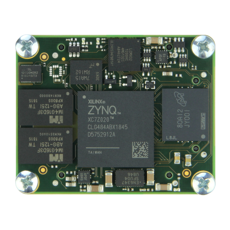
TE0720 User Manual Revision: 0.2 Overview: TE0720 GigaZee Zynq SoM Figure 1: TE0720 GigaZee Zynq SoM (REV 01). Features 1.5A, 4MHz PowerSoC DC-DC Step-Down Converter with Integrated Inductor ( Enpirion EP53F8QI for 1.8V Power Supply System Controller CPLD ( Lattice LCMXO2-1200HC... -
Page 8: Document Change History
Highly Integrated Full Featured Hi-Speed USB 2.0 ULPI Transceiver ( Microchip USB3320C-EZK Document Change History date revision authors description 2014-02-10 Sven-Ole Voigt Work in progress 2013-04-17 Antti Lukats, Thorsten Trenz Initial release Antti Lukats, Thorsten Trenz, Sven-Ole Voigt Copyright © 2014 Trenz Electronic GmbH Page http://www.trenz-electronic.de... -
Page 9: Overview
Revision: 0.2 Overview Trenz Electronic GigaZee XC7Z series are industrial-grade SoMs (system on modules) integrating a leading-edge Xilinx Zynq-7000 SoC, gigabit Ethernet transceiver, 32-bit-wide 1 gigabyte DDR3 SDRAM, 32 megabyte SPI Flash memory for configuration and operation, eMMC, and powerful switch-mode power supplies for all on-board voltages. - Page 10 RTC (real-time clock) MEMS sensor (3-axis accelerometer and 3-axis magnetometer) 3 user LEDs Evenly-spread supply pins for good signal integrity Other assembly options for cost or performance optimization available upon request Copyright © 2014 Trenz Electronic GmbH Page http://www.trenz-electronic.de...
-
Page 11: Getting Started
Preloaded (Factory default) SPI Flash Image The TE0720 module comes with the SPI Flash preloaded with a default bootloader, U-Boot and Linux are setup to run automatically if SPI flash boot mode is selected (Red LED fast blinking after power up). U-Boot is configured with a standard 3 second delay to allow the U-Boot interactive console to be used. - Page 12 Revision: 0.2 Figure 2: Booting Linux Kernel (by default from SPI Flash) - Another (optional) console output, e.g., in HTerm After sucessfully starting the kernel on Xilinx Zynq, the following Linux prompt appears: Copyright © 2014 Trenz Electronic GmbH Page http://www.trenz-electronic.de...
-
Page 13: Boot Procedure
FSBL (First Stage Bootloader) The primary boot source for the TE0720 is the on-board SPI Flash. After power on the Zynq PS boot ROM fetches the FSBL from the SPI Flash and executes it. Then the FSBL code takes over and initializes the Zynq PS peripherals as well as the DDR3 memory controller. -
Page 14: Ssbl (Second Stage Bootloader)
Note: Xilinx wizard generated FSBL does not properly initialize the SD card detect multiplexer values. By default MIO0 remains selected. If writing your own FSBL it is necessary to initialize it properly. TE0720 standard FSBL selects the EMIO63 pin for SD card detect and WP inputs (this forces the card detect to succeed). -
Page 15: Qspi Boot Mode
TE0720 User Manual Revision: 0.2 The TE0720 Zynq SoC Module on the TE0701 Carrier Boards supports two different boot modes: QSPI and SD Card booting. For more information on configuring the boot mode please refer to " TE0701 Carrier Board User Manual | Configuring Boot Mode ". - Page 16 Download boot.bin from host PC to memory address 0x1000000 tftp 0x1000000 boot.bin Initialize SPI Interface sf probe 0 0 0 Write 0x450000 bytes from address 0x1000000 to offset 0 in SPI Flash sf update 0x1000000 0 0x450000 Copyright © 2014 Trenz Electronic GmbH Page http://www.trenz-electronic.de...
-
Page 17: Sd Card Boot Mode
Revision: 0.2 SD Card Boot Mode TE0720 can also boot directly from an SD card. In this mode SPI Flash is not used (all code starting from the FSBL is loaded from the SD card). SDIO0 Bootable slot MIO pins have a 1.8V fixed I/O voltage so the SD card must be connected via a level shifter on the carrier board. -
Page 18: Configuring The Fpga In Linux
/tmp/sd zynq> mount /dev/mmcblk1p1 /tmp/sd zynq> cd /tmp/sd zynq> cat top.bin > /dev/xdevcfg You must apply the write to address 0xF8008070 in U-Boot before booting Linux, otherwise the FPGA load will fail. Copyright © 2014 Trenz Electronic GmbH Page http://www.trenz-electronic.de... -
Page 19: Detailed Description
TE0720 User Manual Revision: 0.2 Detailed Description Overview Figure 2: TE0720 GigaZee Zynq SoM Block Diagram Copyright © 2014 Trenz Electronic GmbH Page http://www.trenz-electronic.de... -
Page 20: System Management, Power Supply & Resets
Figure 3: Overview: TE0720 System Management, Power Supply & Resets Note: The DDR3 SDRAM size depends on assembly option. 1.0V and 1.8V TE0720 power supply circuits are not shown to create a better overview (see TE0720 User Manual | Power Supply for more details). -
Page 21: System Management Controller (Sc)
It is possible for the default SC functions and pin functions to be changed. This can be done as a request to Trenz Electronic or it is possible for the user to generate their own designs. Please contact us for details. -
Page 22: No Sequencing Mode
Pass through FPGA B34 SRCC pin ETH Clock Enable Tied logic high ETH PHY Reset Internal RESET MIO7 LED1 MEMS/RTC I2C XIO to FPGA RTC Interrupt MEMS Interrupt 1 MEMS Interrupt 2 Copyright © 2014 Trenz Electronic GmbH Page http://www.trenz-electronic.de... -
Page 23: Led Control Status
Function 0x20 Status reg 1 0x21 Status reg 2 LED Control Status The TE0720 on-board LED devices can be remapped to different functions. Input port bit Mapped to Ethernet PHY LED0 output Ethernet PHY LED1 output Ethernet PHY LED2 output... - Page 24 TE0720 User Manual Revision: 0.2 LED1 function as Default (MIO7) ETH PHY LED0 ETH PHY LED1 ETH PHY LED2 MIO7 Undefined Undefined Copyright © 2014 Trenz Electronic GmbH Page http://www.trenz-electronic.de...
-
Page 25: Sc Demystified
Peripheral mapping after first init by the FSBL. For use cases where Ethernet PHY on TE0720 is not used at all, it is still possible to configure SC with design that implements I2C Protocol on MIO52/MIO53 pins. - Page 26 Marvell Gigabit PHY and virtual PHY at address 0x1A what is the SC. The above is what uboot will show if the MDIO enable bit was not set in the FSBL. Copyright © 2014 Trenz Electronic GmbH Page...
-
Page 27: Sc Firmware Ver 0.02
This command is needed when standard Xilinx wizard generated FSBL is used with plain standard u-boot, TE0720 u-boot does this initialization also. Note: It seems the problem is in the current u-boot for Zynq, where mii_init function is not defined and not invoked. -
Page 28: Reading Mac Address
Highest bytes of primary MAC Address MACmi Middle bytes of primary MAC Address MAClo Lowest bytes of primary MAC Address reserved do not use MMD_CR MMD Control Register MMD_AD MMD Address/Data reserved do no use Copyright © 2014 Trenz Electronic GmbH Page http://www.trenz-electronic.de... - Page 29 System Controller version 0.02 does not support extended address space - registers 0xD and 0xE are read-write accessible but do not have any function. In feature revision extended address will be used to control SC PLL and other features. Copyright © 2014 Trenz Electronic GmbH Page http://www.trenz-electronic.de...
-
Page 30: Power Supply
(or 500 ms at higher temperatures). If TE0720 is operating in "no power sequencing" mode this period time of 800 ms (and 500 ms, respectively) will never be violated in normal use. TE0720 can also be used in power sequencing mode where the 3.3V voltage plane is supplied from 3.3Vin (CPLD power supply) by a dedicated power FET switch (that is, in turn, controlled via an enable signal by the CPLD SC) after the 1.0V... -
Page 31: I/O Voltages
Dual Supply Application Example power connections. On-board DC-DC converters are supplied separately from 3.3V circuits. All VCCIO Bank Voltages should be derived either from the 3.3V output or controlled by the Power Good signal. Copyright © 2014 Trenz Electronic GmbH Page http://www.trenz-electronic.de... -
Page 32: 3.3V Single Supply With No Power Sequencing
The TE0720 System Managment Controller normally prevents the ZYNQ device from booting if the power is less than 3.05V. In certain cases it is possible to allow the TE0720 module to be operated from a single 2.5V to 2.7V supply. At these voltages the SPI flash boot option is not available and the on-board eMMC is not usable. -
Page 33: Ac & Dc Characteristics
Power saving about 60mW from the PHY power-down, this is only from the PHY IC, Zynq ETH Interface is still in used and clocked, so additional power saving could be achieved by disabling PS ETH as well. Ethernet PHY clock oscillator can be forced into standby, additional 10mW savings. Copyright © 2014 Trenz Electronic GmbH Page http://www.trenz-electronic.de... -
Page 34: Usb Phy Power-Down
TE0720 User Manual Revision: 0.2 USB PHY Power-down USB PHY can be forced into power down by setting the USB PHY Reset active. Copyright © 2014 Trenz Electronic GmbH Page http://www.trenz-electronic.de... -
Page 35: Resets
Note: If TE0720 is used with a full O/S like linaro/ubuntu, and the internal eMMC or external SD card is mounted as a Linux live file system, then it is not recommended to reset the system by asserting RESIN. -
Page 36: Sc Update For Te0720-02
Revision: 0.2 SC update for TE0720-02 TE0720 SC can be updated on TE0703 base board (or on custom baseboards). It is best to check the JTAG configuration with ToolZ to be sure what IC is selected in Chain. Zynq is selected in JTAG, this is normal operational mode. All switches left (ON). - Page 37 Only S3.3 is moved to right (OFF) position. TE0703 onboard baseboard controller CPLD is in JTAG chain with USERCODE CC03xxxx Only S3.2 is moved to right (OFF) position. TE0720 onboard system controller CPLD is in JTAG chain with USERCODE E720xxxx, TE0703 LED's D1, D2 should be both LIT.
-
Page 38: Board-Level Components
TE0720 User Manual Revision: 0.2 Board-level Components Figure 4: Overview: TE0720 Board-level Components Note: The DDR3 SDRAM size depends on assembly option. Copyright © 2014 Trenz Electronic GmbH Page http://www.trenz-electronic.de... -
Page 39: Ddr3 Sdram
MT41J256M16. Two RAM devices are used in a fly-by topology configuration with a 32-bit data width. Different DDR3 devices may be used on different module derivatives. Configuration Setting the DDR3 configuration for the TE0720 is straightforward. Select "Memory Part" as shown in the diagram. Select "Effective DRAM Bus Width" as 32-bit. -
Page 40: E·mmc
Format internal eMMC Card (Linux) Full equipped TE0720-01-*F modules have onboard 4G eMMC card. By default this card not have partitions and not formatted. Below you can see sample eMMC configuration (One primary partition, Linux EXT2... - Page 41 Execute linux command to format partition. To EXT2 zynq> mke2fs /dev/mmcblk0p1 To FAT zynq> mkdosfs /dev/mmcblk0p1 After formatting eMMC drive is ready to use and will be mounted after next reboot. To mount it immediately zynq> mount /mnt/mmc Copyright © 2014 Trenz Electronic GmbH Page http://www.trenz-electronic.de...
-
Page 42: Ethernet
The Ethernet PHY RGMII Interface is connected to the Zynq Ethernet0 PS GEM0 (MIO Pins MIO16..MIO27), I/O Voltage is fixed at 1.8V for HSTL signalling. The internal regulators of the PHY are not used and all power for the device is supplied from the TE0720 DC-DC supplies. -
Page 43: Phy Connections
Zynq device. The remaining pins are connected to the SC that provides logic level conversion and interface translation. When the PL is configured those LED pins can optionally forwarded to the PL Fabric. It is also possible to assign the PHY LEDs to the TE0720 on board LED*s. PHY PIN... -
Page 44: Sgmii/Fiber
Marvell PHY is most likely be left in auto-detect mode after system boot, in such case if copper media is not detected SGMII output is enabled and transmitting. If this is not desired the PHY should be programmed to disable SGMII autodetection. Copyright © 2014 Trenz Electronic GmbH Page http://www.trenz-electronic.de... -
Page 45: Phy Led Control
PHY_LED0_OUT : out STD_LOGIC; -- USER I/O Signal in PMOD J5 PHY_LED1_OUT : out STD_LOGIC; -- USER I/O Signal in PMOD J5 PHY_LED2_OUT : out STD_LOGIC); -- USER I/O Signal in PMOD J5 end PHY_LED_TEST; Copyright © 2014 Trenz Electronic GmbH Page http://www.trenz-electronic.de... -
Page 46: Testing Of The Led's
NET "PHY_LED1_OUT" LOC = Y18; NET "PHY_LED2_OUT" LOC = AA18; Constraint file for TE0720 when used with TE0701 with 3 LED's inserted into into J5 PMOD Testing of the LED's Boot normally and break into u-boot, then use impact or other tool to configure FPGA with the LED Demo .bit file. - Page 47 LED polarity is programmable, default is low(0)=> LED ON zynq-uboot>mii write 0 0x11 0x4415 to change polarity of all LEDs Design files and ready to use bit file (for TE0701-J5) are available from the download area. Copyright © 2014 Trenz Electronic GmbH Page http://www.trenz-electronic.de...
-
Page 48: On-Board Leds
3.3Vout is supplied externally. The 1.0V and 1.8V DC-DC supplies are forced on (NOSEQ=1), board and the SC is not able to start (3.3Vin below 2.1V). This should never happen if the external power supplies are OK. Copyright © 2014 Trenz Electronic GmbH Page http://www.trenz-electronic.de... - Page 49 EN1 input to the module is low. If sequencing is enabled in this mode, then all power supplies blink on the module are OFF. 0.5Hz, 1/8 on, 7/8 off Reset Powered, RESIN input is active low. Copyright © 2014 Trenz Electronic GmbH Page http://www.trenz-electronic.de...
-
Page 50: Todo: Mems
TE0720 User Manual Revision: 0.2 TODO: MEMS In linux MEMS data can be read using device files cat /sys/bus/i2c/devices/2-001e/iio\:device1/in_magn_x_raw current magnetometer X value cat /sys/bus/i2c/devices/3-0018/iio\:device0/in_accel_x_raw current accelerometer X value Copyright © 2014 Trenz Electronic GmbH Page http://www.trenz-electronic.de... -
Page 51: Rtc
General purpose RAM is accessed at I2C slave address 1010111x This RTC IC is supported in Linux so it can be used as hwclock device. RTC data also can be read using device file cat /sys/bus/i2c/devices/2-006f/rtc/rtc0/time Copyright © 2014 Trenz Electronic GmbH Page http://www.trenz-electronic.de... -
Page 52: Usb
USB HS PHY, USB3320 from Microchip (previously SMSC) is used on the TE0720 module. This is the recommended USB PHY for Zynq devices. SMSC offers a design review service for customer schematic and PCB layouts after registration on their website. Note: This design check service does not list USB PHY devices (only LAN Devices), but the SMSC team will consider and reply to design review requests for USB PHY devices too. -
Page 53: Spi Flash
Programming TE0720-02 uses Spansion S25FL256S0 Flash that is fully supported by all Xilinx Tools. TE0720-01 uses Winbond W25Q256 Flash that is supported by Xilinx SDK 2013.4 and 2014.1 (it is not supported by Impact 14.7 or Vivado Programmer 2014). Copyright © 2014 Trenz Electronic GmbH Page http://www.trenz-electronic.de... -
Page 54: Board-Level Interfaces
TE0720 User Manual Revision: 0.2 Board-level Interfaces Figure 5: Overview: TE0720 Board-level Interfaces Note: The DDR3 SDRAM size depends on assembly option. Copyright © 2014 Trenz Electronic GmbH Page http://www.trenz-electronic.de... -
Page 55: Zynq Som: Multiplexed I/O (Mio) Assignments
Example MIO configuration for Bank 0 User I/O. When a PS peripheral is not mapped to a MIO pin it can be used via the Zynq FPGA PL Fabric by using the EMIO interface (Quad SPI is not available via EMIO). Copyright © 2014 Trenz Electronic GmbH Page... -
Page 56: Compatibility With Te07Xx Series
Compatibility with TE07xx series To be compatible with TE0770 and other TE07xx series modules that have gigabit transceivers, the B34 pins that are dedicated pins on those modules should not be used. Copyright © 2014 Trenz Electronic GmbH Page http://www.trenz-electronic.de... -
Page 57: I2C Peripherals
0 7f Valid chip addresses: 1E 20 21 22 38 39 3C 3E 3F 57 6F Example I2C address scan, RTC, MEMS, ADV7513, System Controller and Carried Controller addresses are detected. Copyright © 2014 Trenz Electronic GmbH Page http://www.trenz-electronic.de... -
Page 58: High-Speed I/O
Revision: 0.2 High-Speed I/O TE0720 module is based on the Zynq 7020 which doesn't have any Gigabit transceivers. However in many cases it is possible to use serial links up to 1.25 GBit/s using FPGA I/O resources. Those serial interfaces can be implemented in any FPGA I/O bank when paying attention to the clocking requirements (clock regions). -
Page 59: Board-To-Board Connectors
7.9 GHz / 14 Gbps Mechanical Ratings: Shock: 100G, 6 ms Sine Vibration: 7.5G random, 3 hours 3 axis Manufacturer Documentation: Name Version Date LSHM-1XX-XX.X-X-DV-A-X-X-TR-FOOTPRINT(1).pdf 2013-11-28 16:54 LSHM-1XX-XX.X-XX-DV-A-X-X-TR-MKT.pdf 2013-11-28 16:56 TC0923--2523_report_Rev_2_qua.pdf 2013-11-28 16:55 Copyright © 2014 Trenz Electronic GmbH Page http://www.trenz-electronic.de... - Page 60 TE0720 User Manual Revision: 0.2 Name Version Date hsc-report_lshm-lshm-05mm_web.pdf 2013-11-28 16:56 lshm_dv.pdf 2013-11-28 16:56 tc0929--2611_qua(1).pdf 2013-11-28 16:55 Copyright © 2014 Trenz Electronic GmbH Page http://www.trenz-electronic.de...
-
Page 61: Pinout
B34_L4_P DIFFIO B34_L4_N DIFFIO B34_L5_P DIFFIO B34_L5_N DIFFIO B34_L12_P DIFFIO_CC B34_L12_N DIFFIO_CC B34_L8_P DIFFIO B34_L8_N DIFFIO B34_L9_P DIFFIO B34_L9_N DIFFIO OTG D+ DIFFIO OTG D- DIFFIO OTG ID VBUS_V_EN USB_VBUS B34_L22_P DIFFIO Copyright © 2014 Trenz Electronic GmbH Page http://www.trenz-electronic.de... -
Page 62: Connector Top
DIFFIO B34_L13_P DIFFIO_CC B34_L13_N DIFFIO_CC B34_L21_P DIFFIO B34_L21_N DIFFIO B34_L15_P DIFFIO B34_L15_N DIFFIO B34_L17_P DIFFIO B34_L17_N DIFFIO B34_L23_P DIFFIO B34_L23_N DIFFIO B34_VREF IO_VREF M16/P15 B34_L14_P DIFFIO_CC B34_L14_N DIFFIO_CC Connector top Edit Document Copyright © 2014 Trenz Electronic GmbH Page http://www.trenz-electronic.de... - Page 63 DIFFIO AA16 B33_L18_N DIFFIO AB16 B13_L7_P DIFFIO AA12 B13_L7_N DIFFIO AB12 B13_L8_P DIFFIO AA11 B13_L8_N DIFFIO AB11 B13_L11_P DIFFIO_CC B13_L11_N DIFFIO_CC B13_L9_P DIFFIO AB10 B13_L9_N DIFFIO B13_L20_P DIFFIO B13_L20_N DIFFIO B13_L17_P DIFFIO Copyright © 2014 Trenz Electronic GmbH Page http://www.trenz-electronic.de...
- Page 64 JTAG JTAG JTAG Power input Power input Power input Power input 3.3V 3.3V B33_L4_P DIFFIO B33_L4_N DIFFIO RESIN Reset input B33_L13_P DIFFIO_CC B33_L13_N DIFFIO_CC B33_L14_P DIFFIO_CC B33_L14_N DIFFIO_CC B13_L5_P DIFFIO B13_L5_N DIFFIO Copyright © 2014 Trenz Electronic GmbH Page http://www.trenz-electronic.de...
- Page 65 DIFFIO B13_L4_N DIFFIO B13_L3_P DIFFIO B13_L3_N DIFFIO B13_L10_P DIFFIO B13_L10_N DIFFIO B13_L2_P DIFFIO B13_L2_N DIFFIO B13_L23_P DIFFIO B13_L23_N DIFFIO B13_L24_P DIFFIO B13_L24_N DIFFIO B13_L19_P DIFFIO B13_L19_N DIFFIO B13_L22_P DIFFIO B13_L22_N DIFFIO B13_IO0 Copyright © 2014 Trenz Electronic GmbH Page http://www.trenz-electronic.de...
-
Page 66: Connector Bottom
MIO42 MIO41 MIO40 B35_L16_N DIFFIO B35_L16_P DIFFIO B35_L24_N DIFFIO_ADC B35_L24_P DIFFIO_ADC 1.8V B35_L18_N DIFFIO_ADC B35_L18_P DIFFIO_ADC B35_L15_N DIFFIO_ADC B35_L15_P DIFFIO_ADC B35_L22_N DIFFIO_ADC B35_L22_P DIFFIO_ADC B35_L17_N DIFFIO_ADC B35_L17_P DIFFIO_ADC B35_L13_N DIFFIO_CC B35_L13_P DIFFIO_CC Copyright © 2014 Trenz Electronic GmbH Page http://www.trenz-electronic.de... - Page 67 DIFFIO_CC VBAT VBAT input B35_L20_N DIFFIO_ADC B35_L20_P DIFFIO_ADC MIO15 MIO0 MIO9 MIO11 MIO10 MIO13 MIO12 PHY_MDI0_P DIFFIO PHY_MDI0_N DIFFIO PHY_MDI1_P DIFFIO PHY_MDI1_N DIFFIO PHY_MDI2_P DIFFIO PHY_MDI2_N DIFFIO PHY_MDI3_P DIFFIO PHY_MDI3_N DIFFIO PGOOD Copyright © 2014 Trenz Electronic GmbH Page http://www.trenz-electronic.de...
- Page 68 DIFFIO_ADC B35_L21_N DIFFIO_ADC B35_L21_P DIFFIO_ADC B35_L11_N DIFFIO_CC B35_L11_P DIFFIO_CC B35_L23_N DIFFIO B35_L23_P DIFFIO B35_L5_N DIFFIO_ADC B35_L5_P DIFFIO_ADC B35_L3_N DIFFIO_ADC B35_L3_P DIFFIO_ADC B35_L6_N DIFFIO B35_L6_P DIFFIO MIO14 B35_L1_N DIFFIO_ADC B35_L1_P DIFFIO_ADC B35_L19_N DIFFIO Copyright © 2014 Trenz Electronic GmbH Page http://www.trenz-electronic.de...
- Page 69 TE0720 User Manual Revision: 0.2 B35_L19_P DIFFIO Copyright © 2014 Trenz Electronic GmbH Page http://www.trenz-electronic.de...
-
Page 70: Technical Specifications
TE0720 User Manual Revision: 0.2 Technical Specifications Copyright © 2014 Trenz Electronic GmbH Page http://www.trenz-electronic.de... -
Page 71: Te0720 Board Dimensions & Attributes
TE0720 User Manual Revision: 0.2 TE0720 Board Dimensions & Attributes Dimensions Module size: 50 mm × 40 mm Mating height with standard connectors: 8mm PCB thinkness: 1.6mm highest part on PCB: approx. 2.5mm. Please download the step model for more exact numbers. - Page 72 TE0720 User Manual Revision: 0.2 B2B numbers when looking from top onto carrier board will have odd and even numbers swapped. Copyright © 2014 Trenz Electronic GmbH Page http://www.trenz-electronic.de...
-
Page 73: Power Supplies
0 °C ÷ +70 °C Industrial grade modules -40 °C ÷ +85 °C Depending on the customer design, additional cooling might be required. Weight 16.2 g without bolts 22.4 with bolts screwed to the module Copyright © 2014 Trenz Electronic GmbH Page http://www.trenz-electronic.de... -
Page 74: Te0720 Schematic
TE0720 User Manual Revision: 0.2 TE0720 Schematic The schematic is available for download here: TE0720 (GigaZee) Schematic Copyright © 2014 Trenz Electronic GmbH Page http://www.trenz-electronic.de... -
Page 75: Carrier Boards For Te0720
Moreover, in the following sections is described how the TE0701 Carrier Board can be customized by the Zynq FPGA via the onboard I2C bus and how the interfacing of the TE0701 peripherals is accomplished from the TE0720's point of view. Configuring FMC Power Supply Voltage on TE0701 via I2C (CPLD Firmware Rev 0.1) -
Page 76: Reading I2C-To-Gpio Status Register On Te0701 Cpld (Cpld Firmware Rev 0.1)
To read, e.g., register 0 from I2C device on address 0x22, the command "i2c md 0x22 0" is used. Note : Only one 8-bit status register is available on the TE0720 CPLD Copyright © 2014 Trenz Electronic GmbH Page http://www.trenz-electronic.de... - Page 77 FMC_RSNT# FMC module inserted? yes=0, no=1 POK_FMC "Power ok" signal from the Enpirion EN5335QI DC-DC converter (see TE0720 User Manual | Carrier Boards for TE0720 for more details) SD_DETECT# SD Card inserted? yes=0, no=1 SD_WP Write protection on SD Card enabled? yes=1, no=0...
-
Page 78: Hdmi Interface Of Te0720 On Te0701 Carrier Board
TE0720 User Manual Revision: 0.2 HDMI Interface of TE0720 on TE0701 Carrier Board Zynq FPGA I/O Pins Notes HDMI_CLK HDMI_DE HDMI_VS HDMI_HS HDMI_D0 HDMI_D1 HDMI_D2 HDMI_D3 HDMI_D4 HDMI_D5 HDMI_D6 HDMI_D7 HDMI_D8 HDMI_D9 HDMI_D10 HDMI_D11 Interrupt AA17 CEC_CLK AB16 FPGA should emit some suitable clock on this pin if CEC feature is needed... -
Page 79: Te0720 With Te0603 Carrier
Revision: 0.2 TE0720 with TE0603 Carrier TE0603 was not designed for the TE07xx series, so many new functions are not available. TE0720 will be in "no power sequencing mode" when inserted into a TE0603 baseboard. For proper operation VCCIO must be 3.3V and supplied by the TE0603. -
Page 80: Uart Console
TE0720 User Manual Revision: 0.2 UART Console TE0720 standard flash image uses UART0 for console, baudrate 115200, mapped to MIO pins 14, 15. Those pins are available at J3 pins 24, 37. Digilent PmodUSBUART connected to TE0603 for MIO14,MIO15. Copyright © 2014 Trenz Electronic GmbH Page http://www.trenz-electronic.de... -
Page 81: Carrier Board Checklist
If that is not possible, then adding linear dimensions in the design helps to check that all connectors and mounting holes are properly placed. This placement is same for all 4x5 Modules! Copyright © 2014 Trenz Electronic GmbH Page http://www.trenz-electronic.de... - Page 82 TE0720 User Manual Revision: 0.2 Top view of the Carrier Board. Connector numbers as on base! (pin JB1.1 on base would mate to pin JM1.2 on module). Copyright © 2014 Trenz Electronic GmbH Page http://www.trenz-electronic.de...
-
Page 83: Reference Projects
The feature to create board support packages will hopefully be available with some later Vivado releases, but currently it is not known in which version. At least it is not confirmed for 2014.1 for sure. Copyright © 2014 Trenz Electronic GmbH Page http://www.trenz-electronic.de... -
Page 84: Working With Reference Projects
FSBL from the selected boot source. The TE0720 module supports booting from the on-board QSPI Flash memory and from an external SD memory card. Files from steps 1, 2 and 3 are used to create boot.bin or boot.elf images, which are used to initialize the QSPI Flash memory or an SD memory card. -
Page 85: Projects Build
FSBL - First Stage Boot Loader Create an environment on Ubuntu CentOS Linux to build U-Boot and Linux kernel Build U-Boot Build a Linux kernel, a device tree blob and a ramdisk Copyright © 2014 Trenz Electronic GmbH Page http://www.trenz-electronic.de... -
Page 86: Base Planahead Project
DEPRECATED - use Vivado 2014.2 or newer and start with Board Part Interface flow Run Xilinx PlanAhead 14.5. Click "Create New Project". Click "Next" to continue. Select the project location and click "Next". Copyright © 2014 Trenz Electronic GmbH Page http://www.trenz-electronic.de... - Page 87 TE0720 User Manual Revision: 0.2 Click "Next". Select VHDL as a target language and click "Next". Click "Next". Copyright © 2014 Trenz Electronic GmbH Page http://www.trenz-electronic.de...
- Page 88 TE0720 User Manual Revision: 0.2 Click "Next". Select your chip using the following filter settings: Family: Zynq-7000 Package: clg484 Copyright © 2014 Trenz Electronic GmbH Page http://www.trenz-electronic.de...
- Page 89 TE0720 User Manual Revision: 0.2 Click "Finish" to create the project. Click "Add Sources" in the "Project Manager" tab. Copyright © 2014 Trenz Electronic GmbH Page http://www.trenz-electronic.de...
- Page 90 TE0720 User Manual Revision: 0.2 Select "Add or Create Embedded Sources" and then click "Next". Click "Create Sub-Design..." Copyright © 2014 Trenz Electronic GmbH Page http://www.trenz-electronic.de...
- Page 91 TE0720 User Manual Revision: 0.2 Enter a "Module name" for the Processing System and click "OK". Click "Finish". Copyright © 2014 Trenz Electronic GmbH Page http://www.trenz-electronic.de...
- Page 92 Trenz Electronic Download Area. Click "Import" in the Xilinx Platform Studio window. Click "+" to add a path to the downloaded xml file. Select TE0720-01_a.xml from the list and click "OK". Copyright © 2014 Trenz Electronic GmbH Page...
- Page 93 TE0720 User Manual Revision: 0.2 Click "Yes". processing_system7_0->IIC_1 Select the "Ports" tab in "System Assembly View". Open and configure I2C1_SDA_I, I2C1_SDA_O, I2C1_SDA_T, I2C1_SCL_I, I2C1_SCL_O and I2C1_SCL_T as "External Ports". Copyright © 2014 Trenz Electronic GmbH Page http://www.trenz-electronic.de...
- Page 94 EMIO interface and pass I²C signals and one GPIO pin to the on-board CPLD chip. Inside the CPLD,an I²C switch controlled by a GPIO pin is implemented. Right-click on the created PS (ps.xmp) file and select "Create Top HDL". Copyright © 2014 Trenz Electronic GmbH Page http://www.trenz-electronic.de...
- Page 95 Open the created "ps_stub.vhd" and make the following changes; alternatively, you can replace the created ps_stub.vhd with that contained in the TE0720-01-Base.zip archive from the Trenz Electronic Download Area. Comment external I2C1 and GPIO signals and add CPLD signals to the ps_stub entity. -- processing_system7_0_I2C1_SDA_I_pin : in std_logic;...
- Page 96 : STD_LOGIC_VECTOR(31 downto 0); begin Edit the PS mapping. processing_system7_0_I2C1_SDA_I_pin => ps_i2c_sda_i, processing_system7_0_I2C1_SDA_O_pin => ps_i2c_sda_o, processing_system7_0_I2C1_SDA_T_pin => ps_i2c_sda_t, processing_system7_0_I2C1_SCL_I_pin => ps_i2c_scl_i, processing_system7_0_I2C1_SCL_O_pin => ps_i2c_scl_o, processing_system7_0_I2C1_SCL_T_pin => ps_i2c_sda_t, processing_system7_0_GPIO_I_pin => gpio_i, processing_system7_0_GPIO_O_pin => gpio_o, Copyright © 2014 Trenz Electronic GmbH Page http://www.trenz-electronic.de...
- Page 97 X1 <= ps_i2c_scl_o or ps_i2c_scl_t; -- CPLD SCL B33_L4_P <= ps_i2c_scl_o or ps_i2c_scl_t; -- TE0701 SCL Save the file. Click "Add Sources" in the "Project Manager" tab. Select "Add or Create Constraints" and click "Next". Copyright © 2014 Trenz Electronic GmbH Page http://www.trenz-electronic.de...
- Page 98 TE0720 User Manual Revision: 0.2 TE0720-01_base.ucf Click "Add Files..." and select contained in the TE0720-01-Base.zip archive from the Trenz Electronic Download Area. Press "Generate Bitstream". Press "OK" to close the warning window. Copyright © 2014 Trenz Electronic GmbH Page http://www.trenz-electronic.de...
- Page 99 Wait for the operation to complete. Click "Open Implemented Design". Right click on the PS block and select "Export Hardware for SDK...". Select "Include bitstream", "Export Hardware" and "Launch SDK" and press "OK". Copyright © 2014 Trenz Electronic GmbH Page http://www.trenz-electronic.de...
- Page 100 TE0720 User Manual Revision: 0.2 This step completes the base system build process. The next step describes how to build an FSBL. Copyright © 2014 Trenz Electronic GmbH Page http://www.trenz-electronic.de...
-
Page 101: Base Xps Project
Revision: 0.2 Base XPS Project DEPRECATED - use Vivado 2014.2 or newer and start with Board Part Interface flow Clone the base project from the following Trenz Electronic GitHub repository git clone git://github.com/Trenz-Electronic/TE0720-GigaZee-Reference-Designs.git Or just click on "Download ZIP" to download the full project archive without the need to use git. - Page 102 TE0720 User Manual Revision: 0.2 After build, the project will be opened in SDK. The next step is building the First Stage BootLoader Copyright © 2014 Trenz Electronic GmbH Page http://www.trenz-electronic.de...
-
Page 103: Fsbl - First Stage Boot Loader
In 2013.4 much more error detection is added to the FSBL and the handling of those conditions has been changed by Xilinx. This makes it possible that incorrectly generated 2013.4 FSBL does lock-up and prevents any access to JTAG and SPI Flash (if SPI bootmode is selected). Copyright © 2014 Trenz Electronic GmbH Page http://www.trenz-electronic.de... - Page 104 TE0720 User Manual Revision: 0.2 Copyright © 2014 Trenz Electronic GmbH Page http://www.trenz-electronic.de...
-
Page 105: Creating Fsbl
TE0720 User Manual Revision: 0.2 This is FSBL bootlog on TE0701-03 with TE0720, no manual changes made to the FSBL. SPI flash programmed using Xilinx SDK Flash Programmer. Image includes only FSBL and empty BIT file for FPGA, so all it does is FPGA configuration (done LED goes OFF), and JTAG handoff, enabling all JTAG access. - Page 106 TE0720 User Manual Revision: 0.2 Specify the "Project name" as "FSBL" and the "Board Support Package" as "FSBL_bsp". Click "Next". Select the "Zynq FSBL" template and click "Finish". Copyright © 2014 Trenz Electronic GmbH Page http://www.trenz-electronic.de...
- Page 107 *((u32 *)0xF8000834) = 0x003F003F; // SD1 CD and WP to EMIO63 This way, the SD "Card Detect" and "Write Protect" signals are connected to EMIO63, which should always be bound to logical 0 or left unconnected (floating). Copyright © 2014 Trenz Electronic GmbH Page http://www.trenz-electronic.de...
- Page 108 Select the "FSBL" project from the "Project Explorer" panel and run Xilinx Tools -> Create Zynq Boot Image Click "Add" and select the u-boot.elf file contained in the TE0720-01-U-Boot.zip archive from the Trenz Electronic Download Area, or built from the source code Click "Create Image". Copyright © 2014 Trenz Electronic GmbH Page http://www.trenz-electronic.de...
- Page 109 TE0720 User Manual Revision: 0.2 The newly created .\TE0720-base.sdk\SDK\SDK_Export\FSBL\bootimage\u-boot.bin file should be renamed to boot.bin and placed onto the SD memory card Copyright © 2014 Trenz Electronic GmbH Page http://www.trenz-electronic.de...
-
Page 110: Build Environment
Graphics account; after login, the page provides outdated information about installing ia32-libs. Mentor Graphics Sourcery (formerly: CodeSourcery) toolchain has lots of troubles on 64-bit operating systems; some extra libraries need to be installed, both on CentOS and Ubuntu. Copyright © 2014 Trenz Electronic GmbH Page http://www.trenz-electronic.de... -
Page 111: Centos Linux Kernel And The U-Boot Build Environment
From the VMware Player menu, run the installation of VMware tools: Player -> Manage -> Install VMware Tools In the Terminal window, mount the virtual CD-ROM image and install the VMware tools. mkdir /mnt/cdrom Copyright © 2014 Trenz Electronic GmbH Page http://www.trenz-electronic.de... - Page 112 Mentor Sourcery CodeBench GNU Toolchain installer at http://www.xilinx.com/member/mentor_codebench/xilinx-2011.09-50-arm-xilinx-linux-gnueabi.bin (a Xilinx account is required). Copy the xilinx-2011.09-50-arm-xilinx-linux-gnueabi.bin file to your home directory and run the installation. cp Downloads/xilinx-2011.09-50-arm-xilinx-linux-gnueabi.bin ./ chmod ugo+x xilinx-2011.09-50-arm-xilinx-linux-gnueabi.bin ./xilinx-2011.09-50-arm-xilinx-linux-gnueabi.bin Copyright © 2014 Trenz Electronic GmbH Page http://www.trenz-electronic.de...
- Page 113 CodeSourcery/Sourcery_CodeBench_Lite_for_Xilinx_GNU_Linux/bin/ to the environment variable (preferably by adding it in the script). PATH .bash_profile Now, your virtual machine environment is ready to build U-Boot and the Linux kernel from their source files. Copyright © 2014 Trenz Electronic GmbH Page http://www.trenz-electronic.de...
-
Page 114: Ubuntu Linux Kernel And U-Boot Build Environment
After installation enable shared folder function. Shared folder can be used to pass files between guest and host systems. Open "Virtual machine settings" Go "Options" tab and switch "Folder sharing" to "Always enabled" and press "Add...". Copyright © 2014 Trenz Electronic GmbH Page http://www.trenz-electronic.de... - Page 115 TE0720 User Manual Revision: 0.2 Click "Next". Copyright © 2014 Trenz Electronic GmbH Page http://www.trenz-electronic.de...
- Page 116 TE0720 User Manual Revision: 0.2 Click "Browse" and select folder for sharing. Set name as "shared". Click "Next". Click "Finish". Copyright © 2014 Trenz Electronic GmbH Page http://www.trenz-electronic.de...
- Page 117 On host system. Download xilinx-2011.09-50-arm-xilinx-linux-gnueabi.bin from http://www.xilinx.com/member/mentor_codebench/xilinx-2011.09-50-arm-xilinx-linux-gnueabi.bin (You will need Xilinx account to download). Put downloaded file to shared folder. In virtual machine terminal window. cp /mnt/hgfs/shared/xilinx-2011.09-50-arm-xilinx-linux-gnueabi.bin ./ sudo dpkg-reconfigure -plow dash Copyright © 2014 Trenz Electronic GmbH Page http://www.trenz-electronic.de...
- Page 118 Run "Sourcery CodeBench GNU Toolchain" installation ./xilinx-2011.09-50-arm-xilinx-linux-gnueabi.bin Go through the installation steps choosing the "Typical" installation profile. Now, your virtual machine environment is ready to build U-Boot and the Linux kernel from their source files. Copyright © 2014 Trenz Electronic GmbH Page http://www.trenz-electronic.de...
-
Page 119: U-Boot
TE0720 User Manual Revision: 0.2 U-Boot DEPRECATED - use petalinux 2014.2 or newer and TE0720 BSP Get the U-Boot Repository Start the build environment (CentOS within the VMware Player virtual machine) prepared in the previous CentOS Linux kernel and the U-Boot build environment page. -
Page 120: U-Boot User Scripting
Now, the "u-boot.elf" file can be used to build the Zynq-7000 boot image (last step of the FSBL build process). U-Boot user scripting The default TE0720 u-boot configuration supports user script execution when booting from an SD memory card. The U-Boot script image file u-boot.cmd , if it exists, will be executed before the normal boot. - Page 121 ======= U-Boot user script ========== Pack the script into the u-boot script format: mkimage -T script -C none -n 'User script' -d u-boot.cmd.src u-boot.cmd Copy the u-boot.cmd file to the SD memory card. Copyright © 2014 Trenz Electronic GmbH Page http://www.trenz-electronic.de...
-
Page 122: Linux Kernel 3.9
TE0720 User Manual Revision: 0.2 Linux kernel 3.9 DEPRECATED - use petalinux 2014.2 or newer with TE0720 BSP Get Trenz Electronic Linux Kernel Repository Start the build environment (CentOS within the VMware Player virtual machine) prepared in the previous CentOS Linux kernel and the U-Boot build environment page. - Page 123 TE0720-01-1CF make ARCH=arm TE0720-01-1CF.dtb TE0720-01-1CR make ARCH=arm TE0720-01-1CR.dtb The resulting device tree blob (TE0720-01-2IF.dtb, TE0720-01-2EF.dtb, TE0720-01-1CF.dtb or TE0720-01-1CR.dtb) will be created into the ./arch/arm/boot/dts folder. Rename the resulting device tree blob as by using one of the following commands devicetree.dtb according to the relevant module version.
- Page 124 Locate the files and copy them to the guest system clipboard by pressiing "Ctrl+C". Switch to the Microsoft Windows host system, open a Windows Explorer window, browse to a suitable folder and paste the files from the host system clipboard by pressing "Ctrl+V". Copyright © 2014 Trenz Electronic GmbH Page http://www.trenz-electronic.de...
-
Page 125: Preparing Boot Media
QSPI Flash memory boot Unfortunately, the Winbond W25Q256 QSPI Flash memory assembled on the TE0720 is not yet suported by Xilinx iMPACT software tool. The easiest way to initialize the on-board QSPI Flash memory is to copy the data from the SD memory card using u-boot. - Page 126 Linux kernel image 0x950000 0x020000 devicetree.dtb Linux device tree blob 0x970000 0x5E0000 uramdisk.image.gz Linux ramdisk image To change these addresses, the u-boot default configuration shall be changed and u-boot shall be rebuilt Copyright © 2014 Trenz Electronic GmbH Page http://www.trenz-electronic.de...
-
Page 127: Base Vivado Project
TE0720 User Manual Revision: 0.2 Base Vivado Project Clone the base project from the following Trenz Electronic Github repository https://github.com/Trenz-Electronic/TE0720-GigaZee-Reference-Designs/tree/master/TE0720-01_Base_Vivado-2013.4 or download it from "Download area" http://www.trenz-electronic.de/fileadmin/docs/Trenz_Electronic/TE0720-GigaZee/reference_designs/TE0720-01_Base_Viv Run Vivado 2013.4 In "Tcl Console" cd c:/temp/TE0720-01_Base_Vivado-2013.4/ where "c:/temp" should be replaced to real path to project directory. - Page 128 TE0720 User Manual Revision: 0.2 MIO configuration is Copyright © 2014 Trenz Electronic GmbH Page http://www.trenz-electronic.de...
- Page 129 TE0720 User Manual Revision: 0.2 Click Select "File - Export - Export Hardware for SDK..." Copyright © 2014 Trenz Electronic GmbH Page http://www.trenz-electronic.de...
- Page 130 TE0720 User Manual Revision: 0.2 Select all checkboxes and press "OK" In "Xilinx SDK" window Copyright © 2014 Trenz Electronic GmbH Page http://www.trenz-electronic.de...
- Page 131 TE0720 User Manual Revision: 0.2 Select "File - Import..." Select "General - Existing Projects into Workspace" and press "Next >" Copyright © 2014 Trenz Electronic GmbH Page http://www.trenz-electronic.de...
- Page 132 TE0720 User Manual Revision: 0.2 Check "Select root directory:" and press "Browse". Navigate to "sw_export" directory in project. Check "Copy projects into workspace". Press "Finish" Copyright © 2014 Trenz Electronic GmbH Page http://www.trenz-electronic.de...
- Page 133 TE0720 User Manual Revision: 0.2 Project will build automatically. After complete build, run "Xilinx Tools - Create Zynq Boot Image". Copyright © 2014 Trenz Electronic GmbH Page http://www.trenz-electronic.de...
- Page 134 TE0720 User Manual Revision: 0.2 Select path for output.bif and Add FSBL, bit and u-boot files to Image. Copyright © 2014 Trenz Electronic GmbH Page http://www.trenz-electronic.de...
- Page 135 TE0720 User Manual Revision: 0.2 Click "Create Image". Copy "boot.bin", "devicetree.dtb", "uImage" and "uramdisk.image.gz" files from project directory to SD card. Copyright © 2014 Trenz Electronic GmbH Page http://www.trenz-electronic.de...
-
Page 136: Vivado Flow (Video And Step-By-Step Tutorial)
TE0720 User Manual Revision: 0.2 Vivado Flow (Video and Step-by-Step Tutorial) Creating a Vivado Example Project for TE0720 Zynq SoC Module Video Tutorial (Vivado 2013.2) Step-by-Step Tutorial (Vivado 2013.3) Getting Started: Create New Vivado Project Creating Vivado Block Design (IP Integrator) Software Implementation: Create First Stage Boot Loader (FSBL) and "Hello World"... -
Page 137: Getting Started: Create New Vivado Project
At least it is not confirmed for 2014.1 for sure. Currently, we are working on a patch so that a custom board support package can be made available manually by just copying our TE0720 BSP files into the corresponding Vivado subdirectory (e.g., C: \Xilinx\Vivado\2013.3\data\boards\zynq). Meanwhile, corresponding to the Answer Record AR58180 you have to choose as part the on-board Xilinx Zynq FPGA device (e.g.,... - Page 138 TE0720 User Manual Revision: 0.2 3.) The type of project should be RTL Project with the option "Do not specify soruces at this time" disabled: 4.) The target language is selected to be VHDL: Copyright © 2014 Trenz Electronic GmbH Page http://www.trenz-electronic.de...
- Page 139 TE0720 User Manual Revision: 0.2 5.) ... and in the dialog no existing IP is added... 6.) ... as well as no constraints are specified: Copyright © 2014 Trenz Electronic GmbH Page http://www.trenz-electronic.de...
- Page 140 7.) As long as the Vivado patch has not been released yet (see our notice above), please select the on-board TE0720 Zynq FPGA device (e.g., xc7z020clg484-2): As soon as our custom board "TE0720-01-2EF" will be supported by Xilinx Vivado, it can be chosen in the following way: Copyright ©...
- Page 141 TE0720 User Manual Revision: 0.2 8.) Finally, create the previously parametrized RTL project: Copyright © 2014 Trenz Electronic GmbH Page http://www.trenz-electronic.de...
-
Page 142: Creating Vivado Block Design (Ip Integrator)
1.) Create a new block design and name it. Here, we choose the default name "design_1": 2.) Continue to add new IP (1) from the catalog and select ZYNQ7 Processing System (2): Copyright © 2014 Trenz Electronic GmbH Page http://www.trenz-electronic.de... - Page 143 3.) In the same "Diagram" window a "ZYNQ7 Processing System" block symbol is now visible. After a double click on it, the following "Re-customize IP" dialog will appear, where you click on "Import XPS Settings" and choose the file "TE0720-01_a.xml", which can be found in the archive TE0720-01-Common.zip...
- Page 144 5.) ... (optional) when you would like check by an application on the Zynq FPGA if a SD card is inserted (CD=0) or if its write protection (WP=1) is enabled, then you must assign the corresponding two signals to Copyright © 2014 Trenz Electronic GmbH Page...
- Page 145 (FSBL) because at this stage, the PL has not been configured yet. Of course, in this case the TE0701 CPLD must internally connect the SD_DETECT and SD_WP signals to the corresponding signals, e.g., MIO12 and MIO13, respectively. Alternatively, the values Copyright © 2014 Trenz Electronic GmbH Page http://www.trenz-electronic.de...
- Page 146 SD_DETECT and SD_WP can also be read by the Xilinx Zynq after booting up via the on-board I2C bus (see Carrier Boards for TE0720 | Reading I2C-to-GPIO Status Register on TE0701 CPLD for more details). However, the latest solution will not work for the device manager in Linux. Hence, be...
- Page 147 Revision: 0.2 8.) ... repeat step 6 for the ports FIXED_IO (1), GPIO_0 (2), and IIC_1 (3). Then, manually connect the ports "FCLK_CLK0" and "M_AXI_GP0_ACLK" to each other (4) and regenerate layout (5): Copyright © 2014 Trenz Electronic GmbH Page http://www.trenz-electronic.de...
- Page 148 For this reason, we recommend to use manually the "Make external" function in the context menu as it has been described previously (particularly, when you are planning to edit the corresponding HDL wrapper later as it will be also shown later in this step-by-step tutorial)! Copyright © 2014 Trenz Electronic GmbH Page http://www.trenz-electronic.de...
- Page 149 9.) Then, the corresponding HDL wrapper is created (1) by chosing the non-default option "Copy generated wrapper to allow user edit" (2): 10.) Before the hardware design can be exported, the "IP Integrator" design has to be generated: Copyright © 2014 Trenz Electronic GmbH Page http://www.trenz-electronic.de...
- Page 150 Vivado IP Integrator [Xilinx UG898: Embedded Processor Hardware Design (v2013.3), p.41]: File Description system.xml This file opens by default when you launch SDK and displays the address map of your system. ps7_init.c Copyright © 2014 Trenz Electronic GmbH Page http://www.trenz-electronic.de...
-
Page 151: Software Implementation: Create First Stage Boot Loader (Fsbl) And "Hello World" Application Project In Sdk
SDK 1.) After the SDK GUI has been launched, first of all, a new Xilinx Application Project is created. More First Stage Boot Loader precisely, a Zynq (FSBL) project: Copyright © 2014 Trenz Electronic GmbH Page http://www.trenz-electronic.de... - Page 152 TE0720 User Manual Revision: 0.2 Copyright © 2014 Trenz Electronic GmbH Page http://www.trenz-electronic.de...
- Page 153 TE0720 User Manual Revision: 0.2 Copyright © 2014 Trenz Electronic GmbH Page http://www.trenz-electronic.de...
- Page 154 TE0720 User Manual Revision: 0.2 2.) Secondly, a application project is created, which will be associated with the previously generated Zynq FSBL: Copyright © 2014 Trenz Electronic GmbH Page http://www.trenz-electronic.de...
- Page 155 TE0720 User Manual Revision: 0.2 Copyright © 2014 Trenz Electronic GmbH Page http://www.trenz-electronic.de...
- Page 156 TE0720 User Manual Revision: 0.2 Copyright © 2014 Trenz Electronic GmbH Page http://www.trenz-electronic.de...
- Page 157 TE0720 User Manual Revision: 0.2 3.) Next, the "Hello World" application project can be customized ( Note : Saving all files (3) will automatically rebuild the project): Copyright © 2014 Trenz Electronic GmbH Page http://www.trenz-electronic.de...
- Page 158 TE0720 User Manual Revision: 0.2 4.) Finally, the boot image must be created: Copyright © 2014 Trenz Electronic GmbH Page http://www.trenz-electronic.de...
- Page 159 TE0720 User Manual Revision: 0.2 5.) ... and the newly generated boot image "output.bin" (may be renamed to "boot.bin") and copied onto a SD card, which must be formatted with a FAT32 file system. Copyright © 2014 Trenz Electronic GmbH Page http://www.trenz-electronic.de...
-
Page 160: Hardware Synthesis & Implementation
PS wrapper which communicates with the PS via the EMIO interface and pass I2C signals and one GPIO pin to the on-board CPLD ( TE0720 User Manual | System Management Controller ). Inside the CPLD, an I2C switch controlled by the GPIO pin X0 is implemented. - Page 161 3.) ... replace the port mapping of GPIO (i.e., by commenting the 32 GPIO_0_tri_i, 32 GPIO_0_tri_o, and 32 GPIO_0_tri_t port mappings and replacing them by the corresponding GPIO vectors) as well as I2C1: Copyright © 2014 Trenz Electronic GmbH Page...
- Page 162 VHDL-Code (to copy & paste): GPIO_0_tri_i => gpio_i, GPIO_0_tri_o => gpio_o, GPIO_0_tri_t => gpio_t, IIC_1_scl_i => ps_i2c_scl_i, IIC_1_scl_o => ps_i2c_scl_o, IIC_1_scl_t => ps_i2c_scl_t, IIC_1_sda_i => ps_i2c_sda_i, IIC_1_sda_o => ps_i2c_sda_o, IIC_1_sda_t => ps_i2c_sda_t Copyright © 2014 Trenz Electronic GmbH Page http://www.trenz-electronic.de...
- Page 163 X1 <= ps_i2c_scl_o or ps_i2c_scl_t; -- CPLD SCL i2c_scl_pin <= ps_i2c_scl_o or ps_i2c_scl_t; -- TE0701 SCL 5.) Create a new XDC constraint file and add the following XDC constraint file " design_1_wrapper.xdc ": Copyright © 2014 Trenz Electronic GmbH Page http://www.trenz-electronic.de...
- Page 164 TE0720 User Manual Revision: 0.2 Copyright © 2014 Trenz Electronic GmbH Page http://www.trenz-electronic.de...
- Page 165 Xilinx UG911 (v2013.3) "ISE-Vivado Design Suite Migration Guide"; see section "UCF to XDC Mapping", p.23) to easily convert the physical constraints from an existing UCF input file: #------------------------------------------------------------------------- #-- Copyright (c) 2014 by Trenz Electronic. #-- Holzweg 19a, 32257 Buende, Germany, www.trenz-electronic.de #-------------------------------------------------------------------------...
- Page 166 6.) To synthesize and implement the "Hello World" project, you just have to click on the "Run Implementation" button. Note : Whenever the synthesis is out-of-date, it will be asked if it should be done first: Copyright © 2014 Trenz Electronic GmbH Page http://www.trenz-electronic.de...
- Page 167 "Hello World" project (e.g., X2, X3, X4, X6 etc.), so you can relax and press "ok": 8.) Then, another dialog window appears. Keep the default selection that opens the implemented design: Copyright © 2014 Trenz Electronic GmbH Page http://www.trenz-electronic.de...
- Page 168 (1) and when everything is accurate, the bitfile can be finally generated (2): 10.) As soon as the bitfile has been successfully generated, in another dialog window you can choose to launch Xilinx iMPACT to program your FPGA device: Copyright © 2014 Trenz Electronic GmbH Page http://www.trenz-electronic.de...
- Page 169 11.) In Xilinx iMPACT the project's bitfile "design_1_wrapper.bit" has already been automatically assigned to the xc7z020 target (i.e., the PL of the Xilinx Zynq FPGA). After selecting it (1), you can choose in the main menu "Operations" to finally program the FPGA (2): Copyright © 2014 Trenz Electronic GmbH Page http://www.trenz-electronic.de...
- Page 170 Revision: 0.2 A successful FPGA configuration can only be seen (for now) by checking if the green LED3 (see TE0720 GigaZee Zynq SoM User Manual | On-board LEDs ) has switched off. Because this is admittedly quite a bit unsatisfying, in the following section we will extend our "Hello World"...
-
Page 171: Software Implementation: "Hello World 2.0" (Implementing Access To I2C Peripherals Via Xilinx Zynq Pl Custom Logic)
TE0720 User Manual Revision: 0.2 continue on "How to run an embedded Linux system on TE0720 GigaZee Zynq SoM (Vivado Flow)". Software Implementation: "Hello World 2.0" (implementing access to I2C peripherals via Xilinx Zynq PL custom logic) TODO!!! Debugging the "Hello World" Project Video Tutorial The following screen-recording video shows how to execute "Hello World"... - Page 172 User Manual | User Push Buttons (PBs) and LEDs for more details). 6.) Of course, you can also download the same or a different application onto the running processing unit (PS) of the Zynq FPGA: Copyright © 2014 Trenz Electronic GmbH Page http://www.trenz-electronic.de...
- Page 173 TE0720 User Manual Revision: 0.2 7.) ... and the program execution is (by default) halted in the beginning of "main". By pressing F6 on the keyboard you can debug your program step-by-step: Copyright © 2014 Trenz Electronic GmbH Page http://www.trenz-electronic.de...
- Page 174 TE0720 User Manual Revision: 0.2 Copyright © 2014 Trenz Electronic GmbH Page http://www.trenz-electronic.de...
-
Page 175: Fpga Design Without Ps
TE0720 is a Zynq-7000 SoC based module, and it is normally used with the PS subsystem enabled and included in the design. Of course, it is also possilble to use the TE0720 without instantiating the PS in the design. Such a design can be downloaded into the module through the JTAG port (in a volatile way). It can also be stored to (in a non-volatile way) and loaded at configuration time from QSPI, eMMC or SD Card. -
Page 176: Xilinx Repository
TE0720 User Manual Revision: 0.2 Xilinx repository DEPRECATED - use petalinux 2014.2 or newer and TE0720 BSP Using official Xilinx linux kernel repository with TE0720 This patch was tested only with kernel 3.10 (commit efc27505715e64526653f35274717c0fc56491e3) Known issues: QSPI Flash not working in u-boot Clone linux-xlnx and u-boot-xlnx repositories to prepared environment git clone git://github.com/Xilinx/u-boot-xlnx.git... - Page 177 TE0720 User Manual Revision: 0.2 make ARCH=arm TE0720-01-xxR.dtb Build U-Boot git apply u-boot-xlnx_TE0720.patch make zynq_TE0720_config make Copyright © 2014 Trenz Electronic GmbH Page http://www.trenz-electronic.de...
-
Page 178: High Speed Adc Interfacing
Revision: 0.2 High speed ADC Interfacing TE0720 has no length matching between differential pairs from the FPGA fabric to B2B Connectors. Trace lengths are available in download area, and could be used together with Xilinx provided FPGA Package delay timings to adjust system trace delays. -
Page 179: Petalinux
- this is not an error, MAC address is set correctly and can be seen in linux using ifconfig. Notice that in u-boot it looks like MAC address is not set, as the u-boot variable is not set. Copyright © 2014 Trenz Electronic GmbH Page... -
Page 180: Debug
TE0720 User Manual Revision: 0.2 Debug Copyright © 2014 Trenz Electronic GmbH Page http://www.trenz-electronic.de... -
Page 181: Booting U-Boot Via Jtag
If TE0720 has valid boot images either in SPI Flash or on SD card, it is necessary to prevent linux from loading, either remove SD card, or in case SPI boot, press any key when u-boot loaded from SPI flash is waiting for user input. - Page 182 Select Run->Run As -> Launch on Hardware Open XMD Console In XMD console type stop connect arm hw After this commands system will be initialized and ready to load programms and data to DDR memory. Copyright © 2014 Trenz Electronic GmbH Page http://www.trenz-electronic.de...
- Page 183 Optionally, binary data can be downloaded to memory. This data can be used in u-boot to initialize SPI Flash. dow -data FILENAME.BIN 0x100000 where 0x100000 is location in DDR memory where binary file FILENAME.BIN would be loaded Copyright © 2014 Trenz Electronic GmbH Page http://www.trenz-electronic.de...
- Page 184 TE0720 User Manual Revision: 0.2 Download u-boot.elf file dow b:\u-boot.elf where b:\ should be replaced with actual path to u-boot.elf file Copyright © 2014 Trenz Electronic GmbH Page http://www.trenz-electronic.de...
- Page 185 TE0720 User Manual Revision: 0.2 Copyright © 2014 Trenz Electronic GmbH Page http://www.trenz-electronic.de...
- Page 186 TE0720 User Manual Revision: 0.2 This command runs U-Boot from DDR memory. Copyright © 2014 Trenz Electronic GmbH Page http://www.trenz-electronic.de...
- Page 187 It is is possible to setup everything manually, but it takes time, and some steps need to be done manually each time the TE0720 is powered on. Basically you need to fix the IP addresses so that the TE0720 is visible and accessible from your PC host.
- Page 188 TE0720 User Manual Revision: 0.2 Very important, you must select /hello/stripped/hello as application to download and /hello/hello to load symbols from. If you forget the "stripped" then you get error launching gdbserver! Copyright © 2014 Trenz Electronic GmbH Page http://www.trenz-electronic.de...
-
Page 189: Arm Ds-5
TE0720 User Manual Revision: 0.2 ARM DS-5 debugger view with active gdbserver connection to TE0720 on TE0701 carrier. TE0720 default firmware, gdbserver executable from ARM DS-5 distribution, no custom software needed to make the debugger connection. Copyright © 2014 Trenz Electronic GmbH Page http://www.trenz-electronic.de... - Page 190 TE0720 User Manual Revision: 0.2 Debug session with symbols loaded and ssh console opened to the target. Copyright © 2014 Trenz Electronic GmbH Page http://www.trenz-electronic.de...
-
Page 191: Streamline
Simple modified Helloworld example. This time compiled within DS-5 on a Windows machine and downloaded and executed on a TE0720. Streamline Streamline profiling on TE0720 - a simple screen of activity. when using proper build all that is needed is to add init.sh to SD card #!/bin/sh ifconfig eth0 192.168.140.199... -
Page 192: Compile/Install
Rename the long directory name "CDM v2.08.28 Certified" to "ftd2xx". Plug the FTDI JTAG dongle (TODO: is dongle name correct?) and install the drivers from this directory unless you have the drivers installed already. Copyright © 2014 Trenz Electronic GmbH Page http://www.trenz-electronic.de... - Page 193 ZYNQ_PS.cpu cluster 0 core 0 multi core target state: halted target halted in ARM state due to debug-request, current mode: System cpsr: 0x6000015f pc: 0x0001df18 MMU: disabled, D-Cache: disabled, I-Cache: disabled > mdw 0 4 Copyright © 2014 Trenz Electronic GmbH Page http://www.trenz-electronic.de...
- Page 194 TE0720 User Manual Revision: 0.2 0x00000000: ea000023 ea00000d ea000010 ea00001c > Example session with openocd, target platform 7020 (non ES silicon) on TE0720 using TE0701 on board JTAG circuitry. interface ft2232 ft2232_layout "digilent-hs1" ft2232_latency 2 ft2232_device_desc "Digilent USB Device" ft2232_vid_pid 0x0403 0x6010...
- Page 195 TE0720 User Manual Revision: 0.2 Name Version Date image2013-7-28 10:5:6.png 2013-07-28 08:05 image2013-7-28 10:6:22.png 2013-07-28 08:06 image2013-7-28 9:38:36.png 2013-07-28 07:38 mkopenocd.sh 2013-07-28 22:27 zynq.patch 2013-07-28 21:40 Copyright © 2014 Trenz Electronic GmbH Page http://www.trenz-electronic.de...
-
Page 196: Dcc Console
The above images are compiled version of u-boot from Xilinx git repository. They are just renamed from BIN to ELF. It is possible to execute them on TE0720 as well from SDK debugger. The one of interest is sqpi_single it allows u-boot to access QSPI flash on TE0720. -
Page 197: Handling And Usage Precautions
You must lift positions 1 and 2 at least 1-1.5 mm before proceeding to lift positions 3 and 4. Lift positions 3 and 4 a few millimeters. Repeat with positions 1 and 2 until the module is unplugged. Copyright © 2014 Trenz Electronic GmbH Page... - Page 198 Revision: 0.2 Failure to follow this procedure will very likely cause the left connector to break on the base board, as it is very hard to apply a controlled pull force by hand. Copyright © 2014 Trenz Electronic GmbH Page http://www.trenz-electronic.de...
-
Page 199: Winbond 32Mbyte Spi Flash In 2013.4
FSBL generated with SDK 2013.4 may not boot if some error is detected, in such cases it forces bootrom fall-back in a way that may make the Zynq device to appear as "broken"! This is not related to any hardware issues, TE0720 is alive, ZYNQ is alive, and correct operation can be recovered. -
Page 200: Recovery Instructions
ZYNQ device (both CONTROLR and OUTPUT3 bits are 0). Boundary scan still works, in the screen-shot above "EF401900" is the JEDEC ID from the SPI Flash on TE0720 read using boundary scan (while ZYNQ is in bootrom locked error state). Recovery Instructions: On TE0701 insert SD Card, power-up, remove SD-Card, press Reset button, then reprogram Flash with known good image using SDK 2013.4 Flash Programmer. -
Page 201: Legal Notices
Limitation of Liability In no event will Trenz Electronic, its suppliers, or other third parties mentioned in this document be liable for any damages whatsoever (including, without limitation, those resulting from lost profits, lost data or business interruption) arising out of the use, inability to use, or the results of use of this document, any documents linked to this document, or the materials or information contained at any or all such documents. -
Page 202: Reach (Registration, Evaluation, Authorisation And Restriction Of Chemicals) Compliance Statement
. The products we supply to you are solely non-chemical products (goods). Moreover and under normal and reasonably foreseeable circumstances of application, the goods supplied to you shall not release any substance. For that, Trenz Electronic is obliged to neither register nor to provide safety data sheet.
Need help?
Do you have a question about the TE0720 and is the answer not in the manual?
Questions and answers