Table of Contents
Advertisement
Available languages
Available languages
Quick Links
This wood appliance needs periodic inspection and repair. It is against United States federal regulations to operate this wood
appliance in a manner inconsistent with the operating instructions in this manual.
INSTALLER:
Leave this manual with the appliance.
CONSUMER:
Retain this manual for future reference.
SAFETY INFORMATION
WARNING
!
If the information in these instructions are not followed exactly, a fi re
or explosion may result causing property damage, personal injury or
death. Please read the entire manual before you install and use your
appliance. This heeater has not been tested with an unvented gas log
set. To reduce risk of fi re or injury, do not install an unvented gas log
set into the heater.
- This heater can be very hot when burning.
- Combustible materials such as fi rewood, wet clothing, etc. placed
too close can catch fi re.
- Children and pets must be kept from touching the heater when it is
hot.
- The chimney must be sound and free of cracks. Before installing this
appliance, contact the local building or fi re authority and follow their
guidelines.
- Always operate this appliance with the door(s) or screen (where
applicable) tightly closed.
- Burn wood behind the log retainer directly on the fi rebricks.
- Do not use an elevated grate or otherwise raise the fi re.
- This appliance is designed to burn natural wood only. Higher
effi ciencies and lower emissions generally result when burning air
dried seasoned hardwoods, as compared to softwoods or to green
or freshly cut hardwoods.
- Do not start a fi re with chemicals or fl uids such as gasoline, engine
oil, etc.
- Do not burn trash or garbage, lawn clippings/waste, rubber,
waste petroleum products, paints or paint thinners/solvents, plastic,
materials containing asbestos, construction debris, railroad ties or
treated wood, manure or animal remains, salt water driftwood or
salted materials, unseasoned wood, coal, charcoal, coloured papeer,
cardboard, plywood or particleboard. Burning these materials may
result in release of toxic fumes or render the appliance ineffective and
cause smoke.
- Do not let the appliance become hot enough for any part to glow
red.
Wood Stoves ONLY
- At least 14 squares inches (90.3 square centimeters) of outside air
must be admitted to the room or directly to the appliance through a
4" (101.6mm) diameter pipe.
- KEEP THE STOVE TOP TEMPERATURE BELOW 700°F (371°C).
Attempts to achieve heat output rates that exceed design
specifications can result in steel distortion and damage.
Wolf Steel Ltd., 24 Napoleon Rd., Barrie, ON, L4M 0G8 Canada / 103 Miller Drive, Crittenden, Kentucky, USA, 41030
$10.00
ADD MANUAL TITLE
OPERATION MANUAL
CSA / OMNI
/ INTERTEK
LOGO
Phone 1 (866) 820-8686 • www.napoleon.com • hearth@napoleon.com
INSTALLATION AND
HIGH COUNTRY™ 6000
(MUST use title from Price Book)
ADD PRODUCT IMAGE
THIS APPLIANCE HAS BEEN TESTED AND LISTED BY INTERTEK TESTING
ADD SAFETY STANDARD INFORMATION
SERVICES LTD. AS PER THE STANDARDS: ULC S610, UL 127 FOR
& EPA QUALIFICATION (IF APPLICABLE)
IF INSTALLATION + OPERATION, ADD SERIAL
IF SEPARATE MANUALS, ADD "PLACE
BARCODE LABEL ON THE OWNER'S MANUAL"
ENGLISH
FRENCH PG. 51
Product Name / Code
Low Mass Appliance
ADD ____ ILLUSTRATED
(NZ6000-1 Illustrated)
FOR INDOOR USE ONLY
FACTORY BUILT FIREPLACES.
NUMBER LABEL HERE
W415-1501 / E / 12.17.18
Advertisement
Chapters
Table of Contents

Subscribe to Our Youtube Channel
Related Manuals for Napoleon High Country 6000 Series


Summary of Contents for Napoleon High Country 6000 Series
- Page 1 / INTERTEK BARCODE LABEL ON THE OWNER’S MANUAL” LOGO Wolf Steel Ltd., 24 Napoleon Rd., Barrie, ON, L4M 0G8 Canada / 103 Miller Drive, Crittenden, Kentucky, USA, 41030 Phone 1 (866) 820-8686 • www.napoleon.com • hearth@napoleon.com W415-1501 / E / 12.17.18...
- Page 2 safety information WARNING • This appliance is hot when operated and can cause WARNING severe burns if contacted. • Any changes or alterations to this appliance or its controls can be dangerous and is prohibited. HOT GLASS WILL • Do not operate appliance before reading and CAUSE BURNS.
- Page 3 safety information WARNING • Your appliance requires periodic maintenance and cleaning. Failure to maintain your appliance may lead to smoke spillage in your home. • Ashes must be disposed in a metal container with a tight lid and placed on a non-combustible surface well away from the home or structure until completely cool.
-
Page 4: Table Of Contents
table of contents dimensions selecting wood general information operation general instructions operating sounds and smells features fi re extinguishers, smoke detectors this cordwood fuel appliance and carbon monoxide detectors electrical specifi cations establishing draft packing list fuel loading and burn cycle rating plate information starting the fi... -
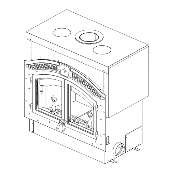
Page 5: Dimensions
1.0 dimensions front view right side view 27 3/16" 690mm 25 1/8" 638mm 49 1/16" 1246mm 1 3/8" 36mm 50 1/8" 1273mm 24 3/16" 614mm 4 1/4" 44 15/16" 1141mm 8 7/16" 108mm 214mm top view 49 1/16" 1246mm 24 1/2" 623mm 14 7/8"... - Page 6 2.0 general information There are many other appliances in the home competing with this appliance for air, such as kitchen range hoods, forced air heating devices, and bathroom exhaust fans. Therefore, in order to avoid fi re hazards and/or injuries, be sure to provide suffi...
-
Page 7: General Information
general information features • Max fuel load 40lbs (18kg) • Maximum log length of 32" (81.3cm) • Large doors for maximum visibility • Optional 320 CFM blower for convection heat • Firebrick lining for fi rebox protection • Thermostat for automatic control of the blower •... -
Page 8: Rating Plate Information
ANGLE DE DÉV 30º US - 45º CANADA W385-2065 / D SERIAL NO. 24 NAPOLEON ROAD. BARRIE, ONTARIO L4M 0G8 CANADA OLEON ROAD. BARRIE, ONTARIO L4M 0G8 CANADA D. BARRIE, ONTARIO L4M 0G8 C DO NOT REMOVE THIS LABEL O NOT REMOVE THIS LABEL... -
Page 9: Installation Overview
3.0 installation overview WARNING • This appliance and its components are designed to be installed and operated as a system. Any alteration to or substitution for items in this system, unless allowed by these installation instructions, will void the ETL listing and may void the product warranty. -
Page 10: Installation Planning
4.0 installation planning WARNING • Wear gloves, protective footwear and safety glasses for protection. • Carefully follow the instructions for assembly of the pipe and other parts needed to install the appliance. Failure to do so may result in a fi re, especially if combustibles are too close to the appliance or chimney and air spacers are blocked, preventing the free movement of cooling air. -
Page 11: Ventilation Openings
Incorporate a vertical loop or trap into air liners to reduce air fl ow when appliance is not in use. Insulating the intake liners is recommended in colder climates to prevent condensation from occurring. The Napoleon Model NZ6000-1 takes outside air directly into the appliance through the openings in the left and right hand sides. -
Page 12: Fl Oor Protection
installation planning fl oor protection 4.4.1 ember strip and hearth extensions WARNING • Hearth extensions are to be installed only as described to prevent high temperatures from occurring on concealed combustible materials. Hearth ember strips prevent burning or hot particles from inadvertently falling directly on combustible surfaces in the event the building should settle and disturb the original construction. -
Page 13: Hearth Extension
installation planning 4.4.2 hearth extension An acceptable 61 ½" (156.2cm) x 20" (50.8cm) non-combustible (ie: brick, SEE HEARTH stone or ceramic tile) hearth extension must be installed. Hearth must EXAMPLES extend 20" (50.8cm) in front of the faceplate when it is not elevated (see local building codes). -
Page 14: Hearth Examples
installation planning 4.4.3 hearth examples FACEPLATE FLUSH HEARTH MIN. 1/4” (6.4mm) TILE OR MARBLE 20” MIN. (50.8cm) COMBUSTIBLE FLOOR EMBER STRIP MIN. 1” (25mm) CEMENT BOARD RAISED HEARTH FACEPLATE 20” MIN. 18" MIN. (50.8cm) (45.7cm) ” (165mm) COMBUSTIBLE FLOOR NON-COMBUSTIBLE MATERIALS EMBER STRIP SUCH AS CEMENT BLOCKS OR BRICKS... -
Page 15: Installation
5.0 installation WARNING • Never install a single wall slip section or smoke pipe in a chase structure. The higher temperature of this single wall pipe may radiate suffi cient heat to combustible chase materials to cause a fi re. •... -
Page 16: Typical Chimney Installation
installation typical chimney installation RAIN CAP RAIN CAP RAIN CAP STORM COLLAR STORM COLLAR STORM COLLAR ROOF FLASHING ROOF FLASHING ROOF FLASHING 15 FT ATTIC INSULATION ATTIC INSULATION ATTIC INSULATION (4.6m) SHIELD SHIELD SHIELD MINIMUM 34 FT (10.4m) 15 FT 15 FT MAXIMUM (4.6m) -
Page 17: Adding Chimney Sections
installation adding chimney sections Add chimney sections, according to the manufacturer’s installation instructions. If the chimney system passes through an attic space, a rafter radiation shield or attic insulation shield is required. The chimney must extend at least 3ft (0.9m) above its point of contact with the roof and at least 2ft (0.6m) higher than any wall, roof or building within 10ft (3.1m). -
Page 18: Offset Chimney Installation
installation offset chimney installation WARNING • Chimney sections installed between an offset and return require structural support to reduce off-center loading and to prevent chimney sections from separating at the chimney joists. • The chimney should not be built with an offset angle in excess of 45° in Canada and 30° in USA. Do not combine offset chimney components to exceed these angles. -
Page 19: Installing Fl Ashing And Storm Collar
installation installing fl ashing and storm collar The following are generic installation instructions for installing the flashing around a chimney. Installation of all types of factory-built chimney systems is to be in accordance with the chimney manufacturer’s installation instructions. Remove the nails from the shingles above and to the sides of the chimney. Place the flashing over the chimney pipe and slide underneath the sides and upper edge of the shingles. -
Page 20: Air Cooled Chimney Installation
installation air cooled chimney installation Remove the knock out. Cut away the insulation to gain access to the ring. STARTER COLLAR Remove the ring secured by four screws. Slide the starter collar through the insulation wrap and affi x using the four screws removed in step C. RING Secure the inner liner of the chimney to the appliance 8"... -
Page 21: Framing
6.0 framing WARNING • In order to avoid the possibility of exposed insulation or vapour barrier coming in contact with the appliance body, it is recommended that the walls of the appliance enclosure be "fi nished" (i.e. drywall/sheetrock), as you would fi... -
Page 22: When Using A Solid Pack Chimney
framing when using a solid pack chimney Cement board and steel studs on enclosure ceiling not required above 10' (3.1m) ENCLOSURE CEILING Metal Studs FLOOR JOISTS Cement board METAL STUDS CEMENT BOARD Face must have a minimum 8' (2.4m) MINIMUM 7' (2.1m) TO BASE OF THE FIREPLACE height of cement board depending upon ceiling height... -
Page 23: Minimum Clearance To Combustibles
framing minimum clearance to combustibles Framed Enclosure Rear - 0" (0mm) to stand-offs (rear) Sides - 6" (152mm) to sides Ceiling - 120" (304.8cm) from the base of the appliance (unless shielded (enclosure) with metal studs and cement board) Ceiling - 84"... -
Page 24: Minimum Mantel Clearances
framing minimum mantel clearances WARNING • Risk of fi re! • Maintain all specifi ed air space clearances to combustibles. Failure to comply with these instructions may cause a fi re or cause the appliance to overheat. Ensure all clearances (i.e. back, side, top, vent, mantel, front, etc.) are clearly maintained. -
Page 25: Finishing
7.0 fi nishing WARNING • Use only a non-combustible material to fi nish the face of the appliance. A non-combustible material such as cement board is required for this purpose. • Ventilation openings are required in enclosures up to 96" (243.8cm) high. They are recommended for all enclosures. -
Page 26: Door Handle Installation
fi nishing door handle installation RIGHT DOOR HANDLE (OPERATING) Insert the door rod through the round hole of the latch, ensuring the fl at edge of the D-shaped hole points towards the hinges. Slide the end of the door rod through the bushing at the top of the door, as shown. -
Page 27: Door Latch Installation
fi nishing door latch installation The door latch is adjusted by moving the washer from one side of the latch to the other. Tighten the outer nut to secure the latch. CROSS-SECTION OF DOOR & GLASS Door Door Latch Rod Frame Door Latch Rod Inner Nut... -
Page 28: Fi Rebrick And Baffl E Installation
fi nishing fi rebrick and baffl e installation WARNING • Operation of the appliance without the baffl es can result in excessive temperatures that could damage the appliance, chimney, and the surrounding enclosure. The by-pass damper should be in the "OPEN" position when using the spark screen, during start-up, when load- ing fuel and in warmer months where less heat is preferred. -
Page 29: Optional Nz64 Blower Installation
fi nishing optional NZ64 blower installation WARNING • All wiring should be done by a qualifi ed electrician and shall be in compliance with local codes and with the National Electric Code ANSI/NF No. 70-Current (in the United States), or with the current CSC22.1 Canadian Electric Code (in Canada). - Page 30 fi nishing Connect the 6” (152.4mm) collar to the blower opening located on the side of the appliance. An optional opening is covered on the other side of the appliance. If this location is preferred, switch the cover plate and collar. Secure by reaching through the collar and bending the tabs. Use sealant to ensure that the connection is air tight.
-
Page 31: Nz150-Kt Kit
fi nishing Connect the 6” (152mm) liner to the appliance and blower collars. Secure using 3 screws on each end and seal with caulking. Liner supplied stretches to a maximum of 10’ (3.1m). Insert the fi lter into the grill. Foam gasket [ ”... -
Page 32: Smoke Shelf
fi nishing 7.12 smoke shelf To reduce smoke spillage due to a poor chimney draft, the NZ6000-1 can be equipped with a smoke shelf exten- sion. note: The smoke shelf is only used when burning with the door open to prevent smoke spillage back into the room. SMOKE SHELF EXTENSION W415-1501 / E / 12.17.18... -
Page 33: Selecting Wood
8.0 selecting wood WARNING • This appliance is designed to burn natural wood only. Do not burn treated wood, coal, charcoal, coloured paper, cardboard, solvents or garbage. This appliance has not been tested with an unvented gas log set. To reduce risk of fi... -
Page 34: Operation
9.0 operation Expansion / contraction noises during heating up and cooling down cycles are normal and to be expected. TIPS FOR BURNING: • Create a large fi re to heat up the appliance before closing bypass door and adjusting to a slower burn. •... -
Page 35: Establishing Draft
When a fi re has been established and it is necessary to reload or adjust the fuel, open the doors slowly to avoid drawing smoke into the room. A properly installed Napoleon appliance should not smoke. If yours does, check the following: •... -
Page 36: Fuel Loading And Burn Cycle
operation fuel loading and burn cycle WARNING • Burn wood behind the log retainer directly on the fi rebricks. Do not use elevated grate or otherwise raise the fi re. • Do not store wood within appliance installation clearances or within the space required for re-fueling and ash removal. -
Page 37: Starting The Fi Re
operation starting the fi re WARNING • Always operate this appliance with the door closed and latched except during start up and re-fueling or unless otherwise noted with compatible Wolf Steel approved accessories. Burning your appliance with the doors open or ajar creates a fi re hazard that may result in a house and/or chimney fi re. Always wear gloves to prevent injury. - Page 38 operation D. To maintain a brisk fi re, a hot E. Slowly add larger wood (2x4 size When the fi re seems to be at its pieces). Lay the pieces lengthwise coal bed must be established peak, medium sized logs may from side to side in the hot and maintained.
-
Page 39: Smoking
operation smoking A properly installed appliance should not smoke. If yours does, check the following: • Has the chimney had time to get hot? • Is the smoke passage blocked anywhere in the appliance, chimney connector or chimney? • Is the room too airtight and the air intake not connected to the outside? Try with a window partly open. •... -
Page 40: Maintenance
10.0 maintenance 10.1 ash removal procedures WARNING • Improper disposal of ashes results in fi res. Do not discard ashes in cardboard boxes, dump in back yards, or store in garages. • If using a vacuum to clean up ashes, be sure the ashes are entirely cooled. Using a vacuum to clean up warm ashes could cause a fi... -
Page 41: Run-Away Or Chimney Fi Re
maintenance 10.3 run-away or chimney fi re WARNING • A chimney fi re can permanently damage your chimney system. This damage can only be repaired by replacing the damaged component parts. Chimney fi res are not covered by the lifetime limited warranty. CAUSES: •... -
Page 42: Glass And Gasket Replacement
maintenance 10.5 glass and gasket replacement WARNING • Make sure that the glass and gasket are fully installed down into the glass retainer. If the glass protrudes too far out of the retainer, the glass will shatter when the door is closed. At the end of each burning season inspect the door gasket ensuring that it is not worn or loose. -
Page 43: Nz64 Blower Replacement
maintenance If the glass should ever crack or break while the fi re is burning, do not open the door until the fi re is out. Do not operate the appliance until the glass has been replaced. Contact your local authorized dealer/distributor for replacement parts. -
Page 44: Replacement Parts
11.0 replacement parts WARNING • Failure to position the parts in accordance with this manual or failure to use only parts specifi cally approved with this appliance may result in property damage or personal injury. Contact your dealer for questions concerning prices and policies on replacement parts. Normally, all parts can be ordered through your Authorized dealer / distributor. -
Page 45: Overview
replacement parts W415-1501 / E / 12.17.18... -
Page 46: Accessories
12.0 accessories W415-1501 / E / 12.17.18... -
Page 47: Troubleshooting
13.0 troubleshooting SYMPTOM PROBLEM TEST SOLUTION Smoke enters the room Cold air blockage in chimney. Burn a piece of newspaper to establish a draft. during start-up. Kindling does not start - Cold air blockage in chimney. Burn a piece of newspaper to establish a draft. fi... -
Page 48: Warranty
During the fi rst 10 years Napoleon will replace or repair the defective parts covered by the lifetime warranty at our discretion free of charge. From 10 years to life, Napoleon will provide replacement parts at 50% of the current retail price. -
Page 49: Service History
15.0 service history W415-1501 / E / 12.17.18... - Page 50 NAPOLEON CELEBRATING OVER 40 YEARS OF HOME COMFORT PRODUCTS 7200, Route Transcanadienne, Montréal, Québec H4T 1A3 24 Napoleon Road, Barrie, Ontario, Canada L4M 0G8 214 Bayview Drive, Barrie, Ontario, Canada L4N 4Y8 103 Miller Drive, Crittenden, Kentucky, USA 41030 Phone: 1-866-820-8686...
- Page 51 / INTERTEK BARCODE LABEL ON THE OWNER’S MANUAL” LOGO Wolf Steel Ltd., 24 Napoleon Rd., Barrie, ON, L4M 0G8 Canada / 103 Miller Drive, Crittenden, Kentucky, USA, 41030 Téléphone 1 (866) 820-8686 • www.napoleon.com • hearth@napoleon.com W415-1501 / E / 12.17.18...
- Page 52 consignes de sécurité AVERTISSEMENT • Cet appareil est chaud lorsqu’il fonctionne et peut causer de graves brûlures en cas de AVERTISSEMENT contact. • Toute modifi cation apportée à cet appareil LA VITRE CHAUDE CAUSERA ou aux contrôles peut être dangereux et est DES BRÛLURES.
- Page 53 consignes de sécurité AVERTISSEMENT • Gardez les matériaux d’emballage hors de la portée des enfants et mettez ces matériaux au rebut de façon sécuritaire. Comme tous les emballages de plastique, ces matériaux ne sont pas des jouets et doivent demeurer hors de la portée des enfants et des bébés. •...
- Page 54 table de matières installation et l'enlévement du dimensions conduit d'air secondaire information générales installation des briques réfractaires instructions générales et du défl ecteur caractéristiques installation de la souffl erie en cette cheminée à combustible option NZ64 bois de corde 7.10 ensemble NZ150-KT spécifi...
-
Page 55: Dimensions
1.0 dimensions vue de côté droite vue frontale 27 3/16" 690mm 49 1/16" 1246mm 25 1/8" 638mm 1 3/8" 36mm 50 1/8" 1273mm 24 3/16" 614mm 4 1/4" 44 15/16" 1141mm 8 7/16" 108mm 214mm vue de dessus 49 1/16" 1246mm 24 1/2"... -
Page 56: Information Générales
2.0 information générales Il y a beaucoup d'autres appareils dans la maison qui sont en compétition avec cet appareil pour l'air, tel que hottes de cuisine, appareils de chauffage d'air forcé, et ventilateurs d'extraction de salle de bains. Donc, afi n d'éviter les risques d'incendie et/ou les blessures, assurez-vous de fournir l'air de combustion suffi... -
Page 57: Cette Cheminée À Combustible
information générales caractéristiques • Longueur maximale des bûches de 32" (81,3cm) • Charge de carburant maximum 40lbs (18 kg). • Souffl erie optionnelle de 320 PCM pour une • Grandes portes vitrées pour un maximum de visi- chaleur de convection bilité... -
Page 58: Information Sur La Plaque D'homologation
ANGLE DE DÉVIAT DE DÉVIA 30º US - 45º CANADA W385-2065 / D SERIAL NO. 24 NAPOLEON ROAD. BARRIE, ONTARIO L4M 0G8 CANADA ARRIE, ONTARIO L4M 0G8 CANADA TARIO L4M 0G8 CANADA DO NOT REMOVE THIS LABEL EMOVE THIS LABEL... -
Page 59: Vue D'ensemble De L'installation
3.0 vue d'ensemble de l'installation AVERTISSEMENT • Cet appareil et ses composants sont conçus pour être installés et fonctionner comme un système. Toute modifi cation ou substitution de composants autre que celles indiqués dans ces instructions d'installation aura pour effet d'annuler la liste ETL et risque d'annuler la garantie. Cela peut aussi créer une installation dangereuse. -
Page 60: Planification D'installation
4.0 planifi cation d'installation AVERTISSEMENT • Portez des gants, chaussures et des lunettes de protection. • Suivez attentivement les instructions pour l’assemblage de la cheminée et des autres composants nécessaires à l’installation de l’appareil. Toute omission pourrait causer un incendie, particulièrement si des matériaux combustibles sont trop près de l’appareil ou de la cheminée eet que des ouvertures d’air sont bloquées, empêchant la libre circulation de l’air de refroidissement. -
Page 61: Ouvertures De Ventilation
plantifi cation d'installation ouvertures de ventilation note: Afi n d'éviter les risques d'incendie et/ou les blessures, l'enceinte de l'appareil doit être fournie d'une circulation d'air suffi sant. Installez une grille d'aération (ouvertures minimales de 40 pouces carrés) au niveau du plancher et une autre au niveau du plafond de l'enceinte. -
Page 62: Protection Du Plancher
plantifi cation d'installation La hauteur verticale de la gaine fl exible de prise d'air ne doit pas GAINES DE LA PRISE D’AIR excéder les 2/3 de la hauteur de la cheminée. Si vous devez ajouter une 10 (20) longueur de gaine fl exible, cette dernière peut être doublée en augmentant son diamètre de 6"(152mm) à... -
Page 63: Base De Protection
plantifi cation d'installation 4.4.2 base de protection VOIR LES Une base de protection incombustible acceptable de 61 ½" (156,2cm) EXEMPLES x 20" (50,8cm) (i.e. briques, pierres ou tuiles de céramique) doit être DE BASES DE installée devant l'appareil. La base de protection doit se prolonger de 20" PROTECTION (50,8cm) à... -
Page 64: Exemples De Bases De Protection
plantifi cation d'installation 4.4.3 exemples de bases de protection BASE À ÉGALITÉ Façade TUILE OU MARBRE MIN. 1/4" (6,4mm) 20" (50,8cm) MIN. PLANCHER COMBUSTIBLE PANNEAU DE CIMENT MIN. 1" (25mm) PARE-BRAISES BASE SURÉLEVÉE Façade 20”(50,8cm) MIN. 18" MIN. (45,7cm) 6" (152mm) PLANCHER COMBUSTIBLE MATÉRIAUX INCOMBUSTIBLES... - Page 65 5.0 installation AVERTISSEMENT • Ne jamais installer un conduit de raccordement à paroi simple dans une enceinte. Les températures plus élevées de ce conduit peuvent irradier suffi samment de chaleur aux matériaux combustibles pour causer un incendie. • Pour éviter un risque d'incendie, vous devez suivre toutes les instructions à la lettre, incluant les dégagements entre le système de conduits et l'enceinte.
-
Page 66: Installation
installation installation typique de la cheminée CHAPEAU CHAPEAU CHAPEAU COLLET DE SOLIN COLLET DE SOLIN COLLET DE SOLIN SOLIN DE TOIT SOLIN DE TOIT SOLIN DE TOIT ÉCRAN DE ÉCRAN DE ÉCRAN DE PROTECTION PROTECTION PROTECTION 15 PI POUR GRENIER POUR GRENIER POUR GRENIER (4,6m) -
Page 67: Ajout De Sections De Cheminée
installation ajout de sections de cheminée Ajoutez des sections de cheminée, selon les instructions d’installation du fabricant. Si la cheminée devra dépasser par l’espace grenier un écran protecteur de chevrons ou une bouclier d'isolation du grenier est requis. La cheminée doit dépasser le toit d’au moins 3’... - Page 68 installation installation de la cheminnée avec déviation AVERTISSEMENT • Les conduits de raccordement installés entre une déviation et un coude de retour requièrent un support afin de réduire la charge excentrée et prévenir toute séparation entre les sections de conduit aux joints. •...
- Page 69 installation installation du solin et du collet de solin Les instructions d’installation suivants sont générales pour l’installation du solin autours de la cheminée. L’Installation de tous les types de systèmes construits en usine doivent être installées en confomé avec les instructions d’installation du fabricant de la cheminée.
- Page 70 installation installation d'une cheminée refroidie à l'air Retirez le disque poinçonné. Découpez l'isolant afi n d'accéder à l'anneau. STARTER COLLAR Retirez l'anneau fi xé par quatre vis. COLLET DE DÉPART Glissez le collet de départ à travers l'isolant et fi xez à l'aide des quatre vis retirées à...
- Page 71 6.0 ossature AVERTISSEMENT • Afi n d'éviter la possibilité que de l'isolant ou un coupe-vapeur d'entrent en contact avec l'extérieur du caisson, il est conseillé d'installer l'appareil contre des murs fi nis (i.e. panneau de gypse), comme tout autre mur de la maison.
- Page 72 ossature installation avec une cheminée préfabriquée standard Panneau de ciment et montants d’acier PLAFOND DE L'ENCEINTE sur l'enceinte plafond à ne pas requise au-dessus 10' (3.1m) SOLIVES DE PLANCHER Montants d'acier Panneau de ciment MONTANT MÉTALLIQUES PANNEAU DE CIMENT La façade doit posséder un panneau de ciment MINIMUM DE 7' À...
- Page 73 ossature dégagements minimaux aux matériaux combustibles Ossature de l'appareil Arrière - 0" (0mm) aux espaceurs (arrière) Côtés - 6" (152mm) des côtés Plafond - 120" (304,8cm) de la base de l'appareil (sauf en cas de protection (enceinte) par des montants métalliques et un panneau de ciment) Plafond - 84"...
-
Page 74: Dégagements Minimaux De La Tablette
ossature dégagements minimaux de la tablette AVERTISSEMENT • Risque d'incendie! • Conservez tous les dégagements aux matériaux combustibles spécifi és. Ne pas respectez ces instructions peut causer un incendie ou une surchauffe. Assurez-vous que tous les dégagements (arrière, côtés, dessus, évents, tablette, façade, etc.) sont respectés à... -
Page 75: Finitions
7.0 fi nitions AVERTISSEMENT • Utilisez uniquement un matériau non combustible pour la fi nition de la façade de l'appareil. Un matériau non- combustible tel un panneau de ciment est requis à cette fi n. • Des ouvertures de ventilation sont requises pour toutes les enceintes allant jusqu'à 96" (243,8cm) de hauteur. Elles sont recommandées pour toutes les enceintes. -
Page 76: Installation De La Poignée De Porte
fi nitions installation de la poignée de porte POIGNÉE DE LA PORTE DROITE (FONCTIONNELLE) Insérez la tige de porte dans le trou circulaire du loquet en vous assurant que le côté plat du trou en forme de « D » est orienté vers les charnières. -
Page 77: Installation De La Poignée De Porte
fi nitions installation de la poignée de porte Vous pouvez ajuster le loquet de porte en déplaçant la rondelle d'un côté du loquet à l'autre. Serrez l'écrou ex- terne pour fi xer le loquet. COUPE TRANSVERSALE DE LA PORTE ET DE LA VITRE Cadre de porte Tige du loquet de porte Tige du loquet de porte... -
Page 78: Installation Des Briques Réfractaires Et Du Défl Ecteur
fi nitions installation des briques réfractaires et du défl ecteur AVERTISSEMENT • L'utilisations de l'appareil sans les défl ecteurs peut causer des températures excessives qui peuvent endommager l'appareil, la cheminée, et l'enceinte. Le défl ecteur ajustable devrait être en position « OUVERTE » lorsque vous utilisez le pare-étincelles, lors de l'allumage, lors du ravitaillement en bois et durant les mois plus chauds où... -
Page 79: Installation De La Souffl Erie En Option Nz64
fi nitions installation de la souffl erie en option NZ64 AVERTISSEMENT • Cet appareil doit être raccordé électriquement par un électrician qualifi é conformément aux codes locaux et à la version courante du National Electrical Code ANSI/NF 70 (aux États-Unis), ou au Code Canadien de l'Électricité... - Page 80 fi nitions Raccordez le collet de 6" à l'ouverture de la souffl erie située sur le côté de l'appareil. Une ouverture alternative est située de l'autre côté de l'appareil. Si cet emplacement est préférable, interchangez la plaque de recouvrement et le collet. Fixez le collet en accédant à l'intérieur de celui-ci et en pliant les pattes.
-
Page 81: Ensemble Nz150-Kt
fi nitions Raccordez la gaine de 6" au collet de l'appareil et à celui de la souffl erie. Fixez chaque extrémité à l’aide de 3 vis et scellez avec du calfeutrage. Le conduit fl exible fourni s'étire jusqu'à un maximum de 10' (3m). Insérez le fi... -
Page 82: Défl Ecteur De Fumée
fi nitions 7.12 défl ecteur de fumée Afi n de réduire les émanations de fumée causées par un tirage inadéquat, vous pouvez ajouter un défl ecteur de fumée optionnel à l'appareil NZ6000-1. note: Le défl ecteur de fumée est seulement utilisé en brûlant avec la porte ouverte pour empêcher les émanations de fumée de retourner dans la pièce. -
Page 83: Sélection Du Bois
8.0 sélection du bois AVERTISSEMENT • Un feu de cheminée peut endommager votre cheminée de façon permnante. Pour réparer ces dommages, vous devrez remplacer les composants endommagés. Les feux de cheminée ne sont pas couverts pas la garantie à vie limitée. Avant de charger l’appareil, assurez-vous que tous les défl... -
Page 84: Fonctionnement
9.0 fonctionnement Les bruits causés par l’expansion et la contraction lors des cycles de chauffage et de refroidissement sont tout à fait normaux et il faut s’y attendre. CONSEILS LORSQUE VOUS FAITES UN FEU: • Faites un grand feu pour réchauffer l’appareil avant de fermer les portes pour régler pour une combustion plus lente. -
Page 85: Contrôle Du Tirage
fonctionnement contrôle du tirage AVERTISSEMENT • Faites toujours fonctionner cet appareil avec la porte fermée et verrouillée, sauf durant l'allumage et le ravitaillement. note: Enlevez tous les contenants d'essence ou autres liquides et vapeurs infl ammables placés à proximité de cet ap- pareil ou tout autre appareil avant de l'allumer. -
Page 86: Chargement Du Bois Et Cycle De Combustion
fonctionnement chargement du bois et cycle de combustion AVERTISSEMENT • Brûlez le bois arrière du pare-bûches directement sur les briques réfractaires. N'utilisez pas un chenet et n'essayez pas de surélever le feu de quelque manière. • N'entreposez pas le bois à l'intérieur des dégagements de l'appareil ou dans l'espace requis pour le ravitaillement ou l'enlèvement des cendres. -
Page 87: Allumer Le Feu
fonctionnement allumer le feu AVERTISSEMENT • Faites toujours fonctionner cet appareil avec la porte fermée et verrouillée sauf durant l’allumage et le ravitaillement ou sauf indication contraire avec compatibles Wolf Steel accessoires. Faire fonctionner cet appareil avec les portes ouvertes ou entrouvertes crée un risque d’incendie de cheminée ou du domicile. Portez toujours des gants pour prévenir les blessures. - Page 88 fonctionnement D. Pour maintenir un feu vif, un lit Lentement, ajoutez des morceaux Lorsque la fl ambée semble être de braises doit se former et être de bois plus gros (2" x 4"). Posez à son maximum, des bûches de entretenu.
-
Page 89: Fumée
fonctionnement fumée Un appareil installé convenablement ne devrait pas fumer. Si le vôtre fume, vérifi ez les points suivants: • Est-ce que la cheminée a pu se réchauffer suffi samment? • Est-ce que le passage de la fumée est bloqué soit dans la cheminée, soit dans le conduit de raccordement, soit dans l’appareil? •... -
Page 90: Entretien
10.0 entretien 10.1 enlèvement des cendres AVERTISSEMENT • Une mise au rebut inadéquate des cendres cause des incendies. Ne jetez pas les cendres dans des boîtes de carton, dans la cour arrière, et ne les entreposez pas dans le garage. •... -
Page 91: Feu De Cheminée Ou Feu Hors Contrôle
entretien 10.3 feu de cheminée ou feu hors contrôle AVERTISSEMENT • Un feu de cheminée peut endommager votre cheminée de façon permnante. Pour réparer ces dommages, vous devrez remplacer les composants endommagés. Les feux de cheminée ne sont pas couverts pas la garantie à... -
Page 92: Remplacement De La Vitre Et Du Joint D'étanchéité
entretien 10.5 remplacement de la vitre et du joint d'étanchéité AVERTISSEMENT • Assurez-vous que la vitre et le joint d'étanchéité sont entièrement insérés dans le cadre de retenue. Si la vitre ressort trop du cadre de retenue, elle se brisera lorsque vous fermerez la porte. À... -
Page 93: Remplacement De La Souffl Erie Nz64
entretien NE FORCEZ JAMAIS POUR LA FERMER! Ne pas faire fonctionner l’appareil avec la verre brisé, les fuites de gaz de combustion peut résulter. Contactez votre détaillant local autorisé pour les instructions de nettoyage complètes. Si la vitre devait fi ssurer pendant que le feu brûle, n’ouvrez pas la porte jusqu’à ce que le feu s’éteigne et n’utilisez pas l’appareil jusqu’à... -
Page 94: Rechanges
11.0 pièces de rechange AVERTISSEMENT • Omettre de positionner les pièces conformément à ce manuel ou d’utiliser uniquement des pièces spécifi quement approuvées pour cet appareil peut causer des dommages matériels ou des blessures corporelles. Contactez votre détaillant pour les questions concernant les prix et la disponibilité des pièces de remplace- ment. -
Page 95: Vue D'ensemble
pièces de rechange W415-1501 / E / 12.17.18... -
Page 96: Accessoires
12.0 accessoires W415-1501 / E / 12.17.18... -
Page 97: Guide De Dépannage
13.0 guide de dépannage SYMPTÔME PROBLÈME SOLUTIONS De la fumée se répand Blocage d’air froid dans la Brûlez un morceau de papier journal pour créer un tirage. dans la pièce durant cheminée. l’allumage. Le bois d’allumage ne Blocage d’air froid dans la Brûlez un morceau de papier journal pour créer un tirage. -
Page 98: Garantie
14.0 garantie Les produits Napoléon sont fabriqués conformément aux normes strictes du Système de Gestion de la Qualité mondialement reconnu ISO 9001 : 2015. Les produits Napoléon sont conçus avec des composants et des matériaux de qualité supérieure, assemblés par des artisans qualifi és qui sont fi... -
Page 99: Historique De Service
15.0 historique de service W415-1501 / E / 12.17.18... - Page 100 À À À T IO ODUITS CONFORT 7200, Route Transcanadienne, Montréal, Québec H4T 1A3 24 Napoleon Road, Barrie, Ontario, Canada L4M 0G8 214 Bayview Drive, Barrie, Ontario, Canada L4N 4Y8 103 Miller Drive, Crittenden, Kentucky, USA 41030 Téléphone: 1-866-820-8686 napoleon.com...
Need help?
Do you have a question about the High Country 6000 Series and is the answer not in the manual?
Questions and answers