Table of Contents
Advertisement
Quick Links
Download this manual
See also:
User Manual
Advertisement
Table of Contents

Related Manuals for Biocontrol Assurance GDS PPMX


Summary of Contents for Biocontrol Assurance GDS PPMX
- Page 1 ASSURANCE GDS® PPMX USER MANUAL 12822 SE 32nd Street Phone 425.603.1123 info@biocontrolsys.com Bellevue, WA, USA 98005 Fax 425.603.0070 www.biocontrolsys.com 55240.R001102015 ...
-
Page 2: Table Of Contents
Table of Contents Safety ........................3 Voltage Safety Interlock Pipette Heads Tip Waste Container Tray Liquids Replacement Parts Introduction ......................5 Standard Equipment Documentation Protocols Disposables Technical Specifications Setup/Operation ....................8 III. Unpacking Removable Tray Rear Panel Connections Front Panel Connections Power On and Start Up Touchscreen Tablet Overview Alignment Protocol Log In Add Pipette Head(s) Set Date & Time Create Users Run a Protocol Step‐by‐step Wizard Pause or Stop a Running Protocol View Results ASSURANCE GDS® PPMX USER MANUAL ... - Page 3 Run Report Import Protocol Export Protocol Change Serial Number in Tablet Software Troubleshooting ....................20 Communication Loss Re‐starting a Protocol after Communication Loss Hood Open Refill Tip Rack Technical Services Maintenance ....................... 22 Cleaning Pipette Head Calibration Alignment Calibration Warranty Instrument Return Procedure Appendix A ......................24 Parts List Appendix B ......................26 VII. Before You Call Us Appendix C ......................27 VIII. Maintenance Log Appendix D ......................28 Warranty Terms Appendix E ......................29 Pipette Verification Appendix F ......................
-
Page 4: Safety
Safety ® Read this section before installing and operating the Assurance GDS PPMX. This instrument is intended to be used in a laboratory environment by trained technical personnel. For safe and proper use of this instrument, it is required that both operating and service personnel follow the instructions contained in this guide when installing, operating, cleaning, and maintaining the instrument. The following safety precautions must be observed during all phases of operation, service, and repair of the instrument. Failure to comply with these precautions or with specific warnings elsewhere in this user’s guide violates safety standards of design, manufacture, and intended use of the instrument. BioControl Systems assumes no liability for the customer’s failure to comply with these requirements. The PPMX has been certified to safety standards required in Canada, Europe, and the United States. Refer to the instrument rear panel label and the Declaration of Conformity document for the current standards to which the instrument has been found compliant. The following electronic and hazard symbols may appear on the instrument: The following safety notices may appear in this document: Voltage Access to the rear panel is necessary because the instrument must be detached from all voltage sources before service, repair, or exchange of parts. Operate the instrument using the approved power supply provided and only at the voltage specified on the rear panel label of the instrument. ASSURANCE GDS® PPMX USER MANUAL ... -
Page 5: Safety Interlock
The instrument is capable of generating significant forces that could cause potential injury to the user. For an instrument with the rotating cover installed, the safety interlock in the cover will disable the instrument movement if the cover on the instrument is open. For an instrument installed in a hood, the external safety interlock sensor mounted on the instrument will disable the instrument movement if the hood door is open. Tip Waste Container The tip waste container should be emptied in accordance with national and local safety regulations. Tray The moving tray is capable of causing injury by pinching. For an instrument with the rotating cover installed, the safety interlock in the cover will disable the instrument movement if the cover on the instrument is open. Liquids Observe safe laboratory practices when handling liquids. If working with biological samples or chemical substances, ensure that there is proper ventilation, and wear personal protective equipment (PPE), such as safety glasses, gloves, and protective clothing at all times. Refer to the Safety Data Sheets for solvents before use. Replacement Parts Be sure to use only replacement parts specified in this user manual. Do not repair or change parts which are not listed in this user manual. If it is necessary to change parts not listed, please contact BioControl Systems technical services. ASSURANCE GDS® PPMX USER MANUAL ... -
Page 6: Introduction
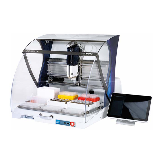
Introduction ® ® The Assurance GDS PPMX is an automated magnetic particles and liquid handler. It is capable of dispensing Assurance GDS reagents which include, Concentration Reagent, Wash Solution, Resuspension Buffer and select media (BHI/DFB). Reagent dispense protocols have been created for all Assurance GDS assays. In addition, the ® PPMX has also been programmed to automate Assurance GDS PickPen Immunomagnetic Separation (IMS) procedures. This user manual is intended to assist PPMX users with system start‐up, basic operation, maintenance and service. Standard Equipment After the PPMX and accessories are unpacked, the following items should be present: PPMX Instrument with attached Alignment Head, Half 8‐channel Tip Ejector Foot and rotating cover • Control Tablet with TRILUTION micro software and Assurance GDS protocols pre‐loaded • Control Tablet Holder • Removable Tray 96 well (x 2) • MAX8x200 Pipette Head • Tip Reload Rack (x 3) • Tip Disposal Bin (x 2) • Assurance GDS Reagent Holder • Assurance GDS PickPen Magnetic Head • Assurance GDS PickPen Tip Puck • • Assurance GDS PickPen Stand • PPMX Gel Cooling Block •... -
Page 7: Documentation
Documentation The following documents are included with the PPMX: User Manual • Quick Setup Guide • Installation/Operation/Performance Qualification (IQ/OQ/PQ) Procedures • Declaration of Conformity • • Validation Certificate for TRILUTION micro • Gilson Quality Control Report Pipette Head Protocols Alignment Protocol • Assurance GDS Reagent Dispense protocols (R‐) • Assurance GDS PickPen IMS protocols (IMS‐) • Disposables The items below are sold separately but are required for use: 200 µL Blister Tip Packs • Reagent Reservoirs • Assurance GDS PickPen Tips • Adhesive Film Sheets & Strips • Assurance GDS Sample Wells & Bases • Resuspension Plates • For part numbers, refer to Appendix A, Parts List. ASSURANCE GDS® PPMX USER MANUAL ... -
Page 8: Technical Specifications
Technical Specifications Please be aware of the following before operating the PPMX. Changes or modifications to this device not expressly approved by BioControl Systems could void the warranty. The instrument complies with part 15 of the FCC Rules. Operation is subject to the following two conditions: (1) This instrument may not cause harmful interference, and (2) this instrument must accept any interference received, including interference that may cause undesired operation. Shielded cables must be used with the instrument to ensure compliance with the FCC Class A limits. Technical Specification Definition Communications USB Connections Three USB host ports and one USB device port Two inputs (contact closure, TTL), two relay outputs, and one switched+12V DC 1A output NOTICE: Switching voltages higher than 30V or greater than 1A of current may damage the instrument Dimensions 54.4 X 65.5 X 53.1 cm (21.4 X 25.8 X 20.9 in) ... -
Page 9: Setup/Operation
Setup/Operation ® ® The Assurance GDS PPMX and its components should be set up in the order described in this section. Gilson TRILUTION® micro provides software control of the PPMX during setup and operation as described in this section. For more information about TRILUTION® micro, view the help information in the software, accessible from the button. Unpacking The PPMX is delivered with most major components already assembled. Keep the original packaging in case the PPMX must be returned to BioControl Systems for repair. It is recommended that two people lift the PPMX out of the box, as it weighs approximately 55 lbs. (24.9 kg). Open top of printed cardboard box. Remove the open‐ended cardboard box. Remove the box of accessories and open it. Lift the printed, outer cardboard box up to remove. Grip the PPMX at the recesses near the base. There is one recess in the front, one in the back, and one on each side. Use these recesses when lifting the PPMX out of the foam‐lined, cardboard tray. Do not attempt to lift the PPMX from the cover or from the X‐arm (the horizontal arm). Always lift the instrument from its base. Place the PPMX on a stable, level surface such as a lab bench, lab cart. Refer to Section 1: Safety. Remove the bag covering the PPMX. You may need to lift the front and the back slightly. Remove the film protecting the rotating cover. Remove the shipping brace from the rear of the instrument. Loosen the thumb screws securing the shipping brace to the PPMX. After removing the shipping brace, replace and tighten the thumb screws. 10 Remove the shipping bracket that attaches the arm to the inside of the unit ... -
Page 10: Removable Tray
Removable Tray A removable tray for placement of labware and tip racks is required. While holding the handles on the sides of the tray, lower the tray onto the metal carrier. It is keyed and will only mount one way. Observe that the tray is level and fully seated on the metal carrier. Rear Panel Connections Refer to the diagrams on the next page when making the connections described in this section. The input/output contacts on the rear panel are used for communication between the alignment head and TRILUTION micro and for communication between the external safety interlock sensor and TRILUTION micro. The contacts can also be used to control peripheral devices. Refer to the diagram for the location of the input/output ports. Contact Inputs – The bottom terminal block on the PPMX has two paired input contacts that are labeled 4 and 5. Never connect voltages higher than 5V DC to an input. When using TTL signals, be sure to match GROUND connections. ... - Page 11 Input/Output USB host (Not Supported) USB host Ethernet (Not Supported) USB device RS‐232 (Not Supported) HDMI (Not Supported) Power receptacle Power switch (MAINS) Use the power cord on the external power supply to make the connection between the power receptacle on the PPMX and the external power supply. The connection from the external power supply to the PPMX uses a connector with a locking collar. Check the alignment of the pins and then push it in until it clicks and locks in place. To disconnect, pull back on the locking collar and then disconnect the cable from the rear panel of the PPMX. Locate the appropriate power cord for your line voltage and then make the connection between the external power supply and the AC power source. ASSURANCE GDS® PPMX USER MANUAL ...
-
Page 12: Front Panel Connections
Front Panel Connections The PPMX has two functional USB host ports on the front panel. The USB ports can be used to connect USB drives (which can also be seen by the tablet when plugged into the PPMX), keyboard, mouse, or any other compatible device (heater/chiller, barcode scanner, or shaker, for example). In a situation where an emergency stop is required, pressing the STOP button stops the PPMX immediately. The protocol stops and results are displayed (after touching OK on the notification). USB host STOP Power On and Start Up To start the PPMX: Make sure that the PPMX is connected to the external power supply and that the external power supply is connected to a power source. Turn power on at the external power supply. Turn the PPMX power on using the MAINS power switch located on the rear panel. The indicator light on the front panel will illuminate green. Connect the control tablet to the PPMX and power it on. Close the rotating cover door. The PPMX will not operate with the cover or hood open. Touchscreen Tablet Overview The following information provides an explanation of unique software interactions when running TRILUTION micro on the supplied touchscreen control tablet. It is recommended to keep the tablet plugged into a power source whenever possible. Communication errors can occur between the PPMX and control tablet if the tablet battery is too low. Refer to the table below for a description of the icons used in the on‐screen keyboard. ASSURANCE GDS® PPMX USER MANUAL ... -
Page 13: Alignment Protocol
The following icons appear on several screens in TRILUTION micro. To view the options to shut down the control tablet and/or TRILUTION micro, touch on the main menu: • Touch Shutdown to close TRILUTION micro and shut down the control tablet. Touch Restart TRILUTION micro to restart only the software, and not the control tablet. • • Touch Cancel to go back to the main menu. Alignment Protocol Run the Alignment Protocol to ensure proper alignment of the PPMX. It is only necessary to run this protocol when setting up the instrument for the first time or if an alignment issue is suspected. Pass the end of the alignment cable cord with pre‐wired connector through the outlet at the back of the PPMX. The connector is labeled BOTTOM because it connects to the bottom set of input/output ports on the rear panel of the PPMX. Make the connection. The clips to secure the tip racks on the tray can interfere with the alignment. Ensure that the clips ( ) are positioned as shown in the diagram below, and that the thumbscrews have been tightened. Close the rotating cover or the fume hood door. The tablet starts TRILUTION micro automatically on power up. Touch Run a protocol. Select Alignment Protocol and then touch Next. ASSURANCE GDS® PPMX USER MANUAL ... -
Page 14: Log In
The Scanning dialog appears while the software checks that the PPMX is connected. If connected, the software goes to the next screen. If not connected, a message will appear suggesting possible solutions. Touch Skip setup on Labware setup guide. 10 Touch Run protocol. 11 Wait approximately 3 minutes while the Alignment Protocol runs. 12 A notification appears when the Alignment Protocol is complete. Touch Continue. Log In Touch Home to go to the main menu. Touch Log in. Enter the User ID and password and after each entry using the on‐screen keyboard on the tablet, and then touch Accept (or the X to cancel). Admin Gilson268 The User ID is and the password is Add Pipette Head(s) Each pipette head that may be used now, or in the future, must be added per the instructions that follow. On the TRILUTION micro main menu, touch Settings. On the Settings menu, touch Pipette heads. Touch Scan and then follow the on‐screen directions to use the tablet camera to scan the barcode on the pipette head, or enter the values from the documentation supplied with each pipette head. ... -
Page 15: Set Date & Time
Set Date & Time Set the date and time to ensure a correct date/time stamp on protocol runs. This should only have to be done once. On the Settings menu, touch Date/time, and then set the date, time, and time zone. Create Users Create users to control access to different areas of the software. To go to the Users screen, touch Users on the main menu. The Users screen displays a list of users. On this screen, a user who is an administrator can create, view, edit, and delete users. Refer to the information below to add users. For information about how to delete users or modify user information, view the help information in the software, from the accessible button. User ID is used when the user logs in. Full name is the full name of the user. Admin? is used to assign administrative access to a user. An Admin can add, delete, and modify users, delete or replace protocols, delete results, change pipette heads, and access the settings options. Change password is used to change or assign the password that is required when the user logs in. To add a user, touch Add and a new row will appear. Touch in the User ID field to assign a user ID. The onscreen keyboard will appear. a) Use the onscreen keyboard to type the User ID. The User ID cannot be the same as any other User ID. • • The User ID can be from 1 to 24 characters. The User ID can use any character that appears on the onscreen keyboard. • b) Touch the check mark to accept the User ID and close the keyboard or touch X to close the keyboard without making any changes. Touch in the Full name field to assign a full name for the user. The onscreen keyboard will appear. a) Use the onscreen keyboard to type the Full name. The Full name can be from 1 to 80 characters. ... -
Page 16: Run A Protocol
Touch Change password to assign a password for the user. The change password screen will appear. a) Touch in the Enter password field. The onscreen keyboard will appear. b) Use the onscreen keyboard to type the password. The password can be any length. • The password can use any character that appears on the onscreen keyboard. • The password is case‐sensitive. • The password is required and cannot be blank. • Touch the check mark to accept the password and close the keyboard or touch X to close the keyboard without making any changes. d) Touch in the Re‐enter password field and re‐type the password. e) Touch Accept to accept the password and close the change password screen. Both passwords must match to be accepted. Or, touch X to close the change password screen without making any changes. Run a Protocol The Labware setup guide screen displays the options for confirming the instrument setup. Select Step‐by‐step wizard to do all of the following (in the order shown): Review a list of the materials. • • Review the layout of the tray and set up pipette head. • Set up the pipette, tip rack and additional labware. • Review protocol / deck. For details, refer to Step‐by‐step Wizard on the next page. Select Browse positions manually to do any of the following: • Review the layout of the tray and review pipette head. Select and set up specific labware. ... -
Page 17: Step-By-Step Wizard
Step‐by‐step Wizard Touch to go to the main menu. Touch Run a protocol. Touch to select your protocol, and then touch Next. The Scanning dialog appears while the software checks that the PPMX is connected. If connected, the software goes to the next screen. If not connected, a message will appear suggesting possible solutions. Enter sample number, kit lot number, and reagent lot numbers and then touch Next. Touch Step‐by‐step wizard. Gather the materials in the Materials List and then touch Next. Wait for the software to finish “Preparing pipette head” and then open the rotating cover or the hood door. Steps 9 – 11 only need to be completed during installation or after running the alignment protocol. Remove the alignment head by disconnecting the terminal block connector from the rear panel, and then removing the thumb nuts securing it to the upper pipette head assembly. 10 Install the pipette head on the left upper pipette head assembly using the thumb nuts. Ensure proper alignment of the pipette head against the upper pipette head assembly before tightening the thumb nuts 11 Select the serial number that matches the installed pipette head from the drop‐down list, close the rotating cover, and then touch Next. 12 Proceed through the Tip setup and Labware setup screens by reviewing the information, making any desired changes, and then touching Next. The screens indicate the labware to use and where to place it on the tray. Each tip rack consists of a tip pack and a tip reload block. To assemble the tip rack: Open the sealed blister pack. Lift the tip pack out of the blister pack. Set the tip pack on the tip reload block. Ensure that the ... -
Page 18: Pause Or Stop A Running Protocol
14 Review protocol / deck and then touch Next. 15 Touch Run protocol. 16 When prompted, it is recommended to simulate if this is the first time running the selected protocol. Pause or Stop a Running Protocol While running a protocol from TRILUTION micro, touch anywhere on the PIPET STATUS image to pause the run. The run will stop when it finishes its current action. The protocol run timer keeps advancing during the pause. When prompted, touch Continue to resume the run, or Stop to end the run and view the results. Do not pause the protocol while pipette tips are being picked up or ejected. To stop the PPMX in an emergency, press the red STOP button on the front of the PPMX. View Results During and after a protocol run, information is available about reagent dispense volumes. After a protocol run, results for that run are automatically displayed. To view results: Touch to go to the main menu. Touch Results. Touch to select a protocol, and then touch Results. Touch to select a protocol run, and then touch View. Simulated runs are identified by . ASSURANCE GDS® PPMX USER MANUAL ... -
Page 19: Run Report
The first screen displayed when viewing results is the Tray view screen. The colors indicate the following information: Red – Negative volume Green – Volume in the tube or well Blue – Empty tube or well Pink – Tips The top of the screen shows the status, the name of the protocol, the time it took to run or simulate the protocol and generate the results, and the time of execution for the last step. The Volume view screen displays information about the volume in the selected well or reservoir. The top of the screen shows the status, the name of the protocol, the time it took to run or simulate the protocol and generate the results, and the time of execution for the last step. The text above the table lists the bed element name, the well location and label, and the current volume in the well. The table lists the actions that occurred in the well or reservoir in the following order: Initial volume (if any) Volume added and the source of the volume added (bed element name and plate index or reservoir number) Volume removed 10 The Steps view screen displays the steps that were run in the protocol in the order of execution. 11 The top of the screen shows the status, the name of the protocol, the time it took to run or simulate the protocol and generate the results, and the time of execution for the last step. Run Report The Run Report is a subset of the results and can be exported for viewing. It cannot be viewed from within the software or on the tablet. It includes basic information about the protocol run, the bed layout, and well tracking. It does not include the information about volume tracking. Touch to go to the main menu. Touch Results. Touch to select a protocol, and then touch Results. Touch to select a protocol run, and then touch Export. Select the file type for the exported file: .htm (default), .xml or .csv. Browse for and select the USB drive, name the file (or accept the default name, which is the name of the protocol), and then touch ... -
Page 20: Import Protocol
Import Protocol To import a protocol: Touch to go to the main menu. Connect a USB drive containing the protocol file to one of the USB ports on the front of the PPMX or the middle USB host port on the rear panel (the top USB port on the rear panel is not supported). Touch Manage protocols to go to the listing of protocols. Touch Import and then browse for your application protocol file (.sqlite) on the USB drive. Select the file and then touch Open to import the protocol file. Export Protocol To export a protocol (and its results): Touch to go to the main menu. Touch Manage protocols to go to the listing of protocols. Touch a protocol in the list. It will highlight when selected. Touch Export. Browse for and select the destination (USB drive) for the protocol file, and then touch Open. The protocol is saved to the location with a .SQLITE extension. Change Serial Number in Tablet Software To control a PPMX from TRILUTION micro, the serial number of PPMX must be entered into TRILUTION micro software. When TRILUTION micro is factory‐installed on the supplied tablet, the serial number of the corresponding PPMX is entered into the software. If installing a replacement tablet, follow the instructions below. Go to the HOME screen. Click Settings. Enter Admin User ID and Password. Click Protocol settings. Enter the Serial number for PPMX. Click Back and return to the HOME screen. ... -
Page 21: Troubleshooting
Troubleshooting TRILUTION micro will display a message if a known error is encountered. This section describes some of the more common errors and how to prevent or resolve them. Communication Loss If a message appears that indicates that the PPMX cannot be found, check your settings (including serial number) and cabling. To re‐establish communication try the following: Turn off the PPMX. Turn off the tablet (press the power button on the HOME screen, then select Turn off tablet). Unplug the PPMX from the control tablet and disconnect the PPMX power cord from the unit. Plug the tablet into the power source to ensure the tablet battery is charging. Wait 5 – 10 min. Reconnect the PPMX to the power supply and the tablet to the PPMX. Power the PPMX on first. Power the control tablet on. Proceed with selecting Run a protocol to check communication has been re‐established. Re‐starting a Protocol after Communication Loss If during a protocol there is a loss of communication between the control tablet and PPMX, the pipette head may be frozen in position. To manually reset the pipette head: From the error message, choose “go to Manual control” or restart the protocol Step‐by‐step wizard and follow prompts until the error message pops up again. Select Manual control. Check the box “Home in recovery mode” and select Home XYZ. Pipette should return to the home position. Hood Open Close the rotating cover door. The PPMX will not operate with the cover or hood door open. While the run is in progress, DO NOT open the hood; however, if the hood has been opened, you will see the following message. If you choose to continue the run, close the rotating ... -
Page 22: Refill Tip Rack
Refill Tip Rack If during a simulation the software calculates that you do not have enough tips to run your protocol or if while running the protocol you run out of tips, the message at below appears. Open the rotating cover, replace or refill the tip rack, close the rotating cover and then touch Continue. Technical Services If you need assistance, please contact BioControl Systems Technical Services at 425.603.1123 or techservices@biocontrolsys.com. To help us serve you quickly and efficiently, please refer to Appendix B. Before Calling Us. ASSURANCE GDS® PPMX USER MANUAL ... -
Page 23: Maintenance
To ensure proper performance of the PPMX the following routine cleaning procedures should be performed on a regular basis. It is recommended that these procedures be carried out at least weekly following reagent dispense protocols or after each run following PickPen IMS protocols. However, based on the specific laboratory environment, more frequent cleaning may be necessary. Always turn the power off to the PPMX before cleaning. To clean the PPMX, lightly spray 70% isopropyl alcohol onto a paper towel and wipe the following instrument surfaces: Removable Tray Pipette Head(s) [avoid introducing any liquid into the openings at the bottom] Tip Reload Rack(s) Tip Disposal Bin(s) PickPen Magnetic Head [avoid introducing any liquid into the openings at the end of the carrier sleeves…exposure of magnets or the inside of the carrier sleeves to moisture may result in corrosion, preventing the device from operating properly] The PPMX Gel Cooling Block and HT Amp Tube Block and Lid (if applicable) should be cleaned by lightly spraying a paper towel with 10% bleach solution and wiping the outside. Follow with 70% isopropyl alcohol as described above to remove potentially corrosive residues. To clean the control tablet, wipe the touchscreen with a low lint cloth designed for electronics. Do not use pre‐moistened alcohol wipes to clean the control tablet. Leave rotating cover down when instrument is not in use. For a maintenance log, please refer to Appendix C. Maintenance Log. Pipette Head Calibration To ensure proper performance of the pipette head cassette, it should be calibrated annually as a minimum. Contact BioControl Systems Technical Services at 425.603.1123 or techservices@biocontrolsys.com. To help us serve you quickly and efficiently, please refer to Appendix B. Before Calling Us. It may be necessary to exchange pipette head cassettes while one is out for calibration. When exchanging a pipette head it is necessary to do two things: Add the pipette head to the software by scanning or entering the calibration values. For detailed instructions, refer to Add Pipette Head(s). Physically install the head on the instrument. For detailed instructions and a diagram, refer to Step‐by‐ step wizard. To verify the pipette head performance, please refer to Appendix E. Pipette Verification. ASSURANCE GDS® PPMX USER MANUAL ... -
Page 24: Alignment Calibration
Alignment Calibration It may be necessary to run the Alignment Protocol to ensure proper alignment of the PPMX if the unit is moved or an alignment issue is suspected. For detailed instructions and a diagram, refer to Run Alignment Protocol. Warranty Units that are under warranty will be repaired and returned to the user at no charge. Please refer to Appendix D. Warranty Terms. If you have any questions about applicability, contact your local Biocontrol Systems representative. For out‐of‐warranty repairs, contact your local Biocontrol Systems representative who will discuss service options with you. Instrument Return Procedure Contact BioControl Systems Technical Services at 425.603.1123 or techservices@biocontrolsys.com to obtain authorization before returning any BioControl Systems equipment. To help us serve you quickly and efficiently, please refer to Appendix B. Before Calling Us. To return a piece of equipment: • Carefully pack the unit in original container to prevent damage in transit. Please refer to Appendix F. Pack Up. Check with Technical Services regarding proper method of shipment. No responsibility is assumed by BioControl Systems for damage caused by improperly packaged instruments. Indicate the return authorization on the carton and on the packing slip. Always insure for the replacement value of the unit. • ASSURANCE GDS® PPMX USER MANUAL ... -
Page 25: Parts List
Appendix A Parts List Equipment Description BCS Part Number 79100‐01 PPMX WITH STANDARD COVER 79120 CONTROL TABLET WITH BCS TRILUTION MICRO SOFTWARE 79104 CONTROL TABLET HOLDER 79106 MAX8x200 PIPETTE HEAD 79110 ALIGNMENT HEAD 79101 REMOVABLE TRAY 96 WELL 79105 TIP RELOAD RACK 79109 TIP DISPOSAL BIN 79103 ASSURANCE GDS REAGENT HOLDER 79126 ASSURANCE GDS PICKPEN MAGNETIC HEAD 79127 ASSURANCE GDS PICKPEN TIP PUCK 79133 ASSURANCE GDS PICKPEN STAND 79128 HALF 8‐CH TIP EJECTOR FOOT 79125 PPMX GEL COOLING BLOCK 79134 PPMX HT AMP TUBE HOLDER WITH LID 79132 PPMX HT AMP TUBE CAPPING TOOL 79116 USB CABLE 79121 BLACK PLUG FOR BACK COVER ... - Page 26 Disposables Description BCS Part Number 79102 DIAMOND BLISTER, DF200ST, FILTER, 960 TIPS 79107 4‐COLUMN REAGENT RESERVOIR, CASE OF 25 79109 1‐COLUMN REAGENT RESERVOIR, CASE OF 25 73087 ASSURANCE GDS PICKPEN II TIPS, RACKED 73085 ASSURANCE GDS PICKPEN II TIPS, BULK 73004 ADHESIVE FILM SHEETS, BOX OF 100 73026 ADHESIVE FILM STRIPS, BOX OF 200 73043 SAMPLE WELL BASE, BAG OF 10 73044 SAMPLE WELLS, BAG OF 200 73006 RESUSPENSION PLATES, CASE OF 120 ASSURANCE GDS® PPMX USER MANUAL ...
-
Page 27: Before You Call Us
Appendix B Before You Call Us BioControl Systems Technical Services will be able to serve you more efficiently if you have the following information on hand: Serial number of the instrument(s) involved: • The serial number for the PPMX is located on the inside panel of the right support. The serial number for the pipette head is located on the outside of the casing. The serial number for the PickPen magnetic head is located on the outside of the casing. The serial number for the control tablet is located on the bottom of the tablet. • List of concise symptoms being exhibited by the instrument. List of operating procedures / protocols and conditions you were using when the problem arose. • List of all instruments in the configuration and the connections to those instruments. • List of other electrical connections in the room. • ASSURANCE GDS® PPMX USER MANUAL ... -
Page 28: Maintenance Log
Appendix C Maintenance Log ASSURANCE GDS® PPMX USER MANUAL ... -
Page 29: Warranty Terms
Appendix D Warranty Terms BioControl Systems, Inc. (“BioControl” or “BCS”) warrants the Assurance GDS PickPenPIPETMAX automation equipment to be free from defects in materials and workmanship, when given normal, proper, and intended usage for one (1) year from the date of delivery of this equipment to the original purchaser (“Buyer”). BioControl agrees during the applicable warranty period to repair or replace, at BioControl’s option, all defective equipment within 5 days after date of return to BioControl and without cost to Buyer. This Limited Warranty shall apply to the following EQUIPMENT included in the Assurance GDS PIPETMAX System; Assurance GDS PickPenPIPETMAX and control tablet. BioControl shall not have any obligation under this Limited Warranty to make repairs or replacements which are required by normal wear and tear, or which result, in whole or in part, from catastrophe, fault or negligence of the Buyer, or anyone claiming through or on behalf of the Buyer, or from improper use of the equipment, or use of the equipment in a manner for which it was not designed, or by causes external to the equipment. Buyer shall notify BioControl of any equipment believed to be defective during the warranty period. At BioControl’s option, such equipment shall be returned by Buyer, transportation and insurance prepaid, to BioControl’s designated facility for examination and testing. BioControl shall repair or replace, within 5 days of receipt by BioControl, any such equipment found to be defective and promptly return such equipment to Buyer, transportation and insurance prepaid. Should BioControl’s examination and testing not disclose any defect covered by the foregoing warranty, BioControl shall so advise Buyer and return the equipment in accordance with buyer’s instructions and at Buyer’s sole expense. BioControl warrants its repair work and any replacement parts or equipment for a period of 30 days from receipt by the Buyer of the repaired or replaced equipment or for the remaining balance of the original warranty period set forth in the preceding paragraph, whichever is greater. THE PROVISIONS OF THE FOREGOING LIMITED WARRANTY ARE IN LIEU OF ANY OTHER WARRANTY, WHETHER EXPRESS OR IMPLIED, WRITTEN OR ORAL INCLUDING ANY WARRANTY OF MERCHANTABILITY OR FITNESS FOR A PARTICULAR PURPOSE. BIOCONTROL’S LIABILITY ARISING OUT OF THE MANUFACTURE, SALE OR SUPPLYING OF THE EQUIPMENT OR ITS USE OR DISPOSITION, WHETHER BASED UPON WARRANTY, CONTRACT, TORT OR OTHERWISE, SHALL NOT EXCEED THE ACTUAL PURCHASE PRICE PAID BY BUYER FOR THE EQUIPMENT. IN NO EVENT SHALL BIOCONTROL BE LIABLE TO BUYER OR ANY OTHER PERSON OR ENTITY FOR SPECIAL, INCIDENTAL OR CONSEQUENTIAL DAMAGES (INCLUDING, BUT NOT LIMITED TO, LOSS OF PROFITS OR LOSS OF USE DAMAGES) ARISING OUT OF THE MANUFACTURE, SALE OR SUPPLYING OF THE EQUIPMENT. THE FOREGOING WARRANTIES EXTEND TO BUYER ONLY AND SHALL NOT BE APPLICABLE TO ANY OTHER PERSON OR ENTITY INCLUDING, WITHOUT LIMITATION, CUSTOMERS OF BUYER. ... -
Page 30: Pipette Verification
Appendix E Pipette Verification When neccesary, the following procedure can be used to verify PPMX pipette head performance: Select “Run a protocol” Select R – Standard Low Micro protocol Enter 8 samples Weigh 2 empty GDS Sample Bases with one sample well strip each and 1 GDS Resuspension Plate prior to start and record weight Load removable tray with disposables according to PPMX Step‐by‐step wizard Enter correct number of missing tips if not using a full rack Vortex Concentration Reagent and remove cap prior to adding bottle to the GDS Reagent Holder Add correct volume of Wash Solution and Resuspension Buffer to reagent reservoir Select “Run protocol” Select “Skip” when asked to simulate Select “Continue” to prompt When run is completed, weigh both filled GDS Sample Bases and the filled GDS Resuspension Plate and record weight Complete the following calculation for each of the 3 reagents: (FP – DP) / 8 wells = ______________ x 1000 = __________ µL Dry Plate (DP) Weight of Sample Blocks/Resuspension Plate Concentration Reagent g Wash Solution g RS Plate Resuspension Buffer g Filled Plate (FP) Weight of Sample Blocks/Resuspension Plate Concentration Reagent g Wash Solution g RS Plate Resuspension Buffer g Pipette should deliver 20 ± 1 µL for Concentration Reagent, 1000 ± 20 µL for Wash Solution, and 45 ± 2 µL for Resuspension Buffer. Concentration Reagent __________ µL Wash Solution __________ µL Resuspension Buffer __________ µL ... -
Page 31: Pack Up
Appendix F Pack Up Unplug the Assurance GDS PPMX, place the power supply in the mini cardboard box and put into the bottom of the PPMX accessories box Unplug the control tablet, place the black USB cable in its plastic bag and put into the PPMX accessories box Place control tablet and charger back into the labeled tablet box and put into the PPMX accessories box Place all the deck accessories into their plastic bags and place into the PPMX accessories box Trash bin, tip reload racks, tip puck, reagent holder, gel block and power cords (US & EU) b. Dispose of used reservoirs, sample wells and tips Place the control tablet holder in its labeled box, place in a separate cardboard box Rotate the clear cover open until it catches on the magnets PPMX Accessories box Secure the cover by installing the shipping brace onto the rear of the instrument with thumb screws Remove the 8x200 Pipette Head by unscrewing the thumb nuts securing ... - Page 32 Install the Alignment Head on the left side of the PPMX arm by securing it to the upper Pipette Head assembly with the thumb nuts Alignment Head Remove the PickPen Magnetic Head by unscrewing the thumb nuts securing it to the right side of the arm. Wrap the PickPen Head in bubble wrap and place in the PPMX accessories box Remove the deck tray and set aside, slide the metal bottom sheet back so that the rectangular hole aligns with the opening in the base and press the foam block into the opening to prevent the sheet from moving during shipping Tape the Alignment Head cable to the foam block Install the shipping bracket to the arm and inside back of the PPMX by using the allen wrench provided to tighten both screws into place ASSURANCE GDS® PPMX USER MANUAL ...
- Page 33 Carefully lower the PPMX into the foam insert in the base of the shipping container, the handholds on opposite ends of the instrument match with the clearance notches in the foam. Place the plastic bag over the unit. Place the shipping container lid on top of the instrument, making sure it fits snugly around the bottom foam insert Tape up the PPMX accessories box and slide it in the shipping container behind the PPMX, the cut out hand holes should match up with the handholds on the shipping container Hand holds Place the removable metal deck trays into bubble wrap or their cardboard wrappers and put them in the separate cardboard box with the control tablet holder ASSURANCE GDS® PPMX USER MANUAL ...
- Page 34 Place the open sleeve in the front of the PPMX (should remain empty), the cut out hand holes should match up with the handholds on the shipping container Make sure that the clear cover stays open with magnets engaged…the foam should rest just below the handle Place the two grey foam inserts vertically on the sides of the PPMX for additional protection Place bubblewrap/cardboard cover on top of the PPMX and tape the shipping container Secure the shipping container to the pallet using plastic banding or the included ratchet straps, be sure to use the cardboard edge protectors supplied to prevent damage to the shipping container Alternatively, a wooden crate/pallet may be used to ship the PPMX ...
Need help?
Do you have a question about the Assurance GDS PPMX and is the answer not in the manual?
Questions and answers