Tektronix TLA7PG2 Instructions Manual
Pattern generator module
Hide thumbs
Also See for TLA7PG2:
- Service manual (253 pages) ,
- Instruction manual (66 pages) ,
- Security instructions (4 pages)
Table of Contents
Advertisement
Quick Links
Download this manual
See also:
Instruction Manual
Instructions
TLA7PG2
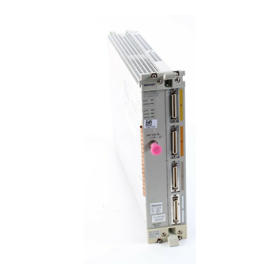
Pattern Generator Module
071-1306-00
Warning
The servicing instructions are for use by qualified
personnel only. To avoid personal injury, do not
perform any servicing unless you are qualified to
do so. Refer to all safety summaries prior to
performing service.
www.tektronix.com
*P071130600*
071130600
Advertisement
Table of Contents

Related Manuals for Tektronix TLA7PG2


Summary of Contents for Tektronix TLA7PG2
- Page 1 Instructions TLA7PG2 Pattern Generator Module 071-1306-00 Warning The servicing instructions are for use by qualified personnel only. To avoid personal injury, do not perform any servicing unless you are qualified to do so. Refer to all safety summaries prior to performing service.
- Page 2 Copyright © Tektronix, Inc. All rights reserved. Licensed software products are owned by Tektronix or its suppliers and are protected by United States copyright laws and international treaty provisions. Use, duplication, or disclosure by the Government is subject to restrictions as set forth in subparagraph (c)(1)(ii) of the Rights in Technical Data and Computer Software clause at DFARS 252.227-7013, or subparagraphs (c)(1) and (2) of the...
- Page 3 Tektronix, with shipping charges prepaid. Tektronix shall pay for the return of the product to Customer if the shipment is to a location within the country in which the Tektronix service center is located.
-
Page 5: Table Of Contents
......... . Appendix A: TLA7PG2 Pattern Generator Module Characteristics Appendix B: Pattern Generator Physical-Logical Conversion . - Page 6 ......List of Tables Table i: Tektronix TLAPG2 Pattern Generator Module documentation ........
-
Page 7: General Safety Summary
Keep Product Surfaces Clean and Dry. Provide Proper Ventilation. Refer to the manual’s installation instructions for details on installing the product so it has proper ventilation. Symbols and Terms Terms in this Manual. These terms may appear in this manual: TLA7PG2 Pattern Generator Module Instructions... - Page 8 WARNING indicates an injury hazard not immediately accessible as you read the marking. CAUTION indicates a hazard to property including the product. Symbols on the Product. The following symbols may appear on the product: CAUTION Refer to Manual TLA7PG2 Pattern Generator Module Instructions...
-
Page 9: Preface
Tektronix representative. Table i: Tektronix TLAPG2 Pattern Generator Module documentation Location TLA Documentation Documents available in printed form and downloadable from the Tektronix web site. Tektronix Logic Analyzer Family User Manual TLA700 Series Installation Manual TLA7PG2 Probe Instruction Manual TLA7UP Field Upgrade Kit Instructions tektronix.com... -
Page 10: Contacting Tektronix
This phone number is toll free in North America. After office hours, please leave a voice mail message. Outside North America, contact a Tektronix sales office or distributor; see the Tektronix web site for a list of offices. TLA7PG2 Pattern Generator Module Instructions... -
Page 11: Pattern Generator Module Introduction
You can connect up to four probes to a single module. Each probe supports either 8 or 16 channels. For information about connecting the Pattern Generator probes to both the TLA7PG2 module and the target system, refer to the TLA700 Series Logic Analyzer Installation Manual. Pattern Generator Program The pattern generator program is the heart of the pattern generator module. - Page 12 This is useful for trouble- shooting or debugging setups. For information about installing the Pattern Generator program, refer to the TLA700 Series Logic Analyzer Installation Manual. TLA7PG2 Pattern Generator Module Instructions...
-
Page 13: Setting Up The Pattern Generator Module
H Use the Event setups to filter out events, enable inhibit functions, and to define whether the pattern generator responds to events due to edges or levels. TLA7PG2 Pattern Generator Module Instructions... -
Page 14: Channel Setup Window
Use this window to define the channel group names, the logical grouping of channels, and the individual channel names. Figure 3 shows an example of the Channel Setup window. Figure 3: Channel Setup window TLA7PG2 Pattern Generator Module Instructions... -
Page 15: Probe Setup Window
For more information on using signals, refer to the Intermodule and External Signaling section in the Tektronix Logic Analyzer Family User Manual. Figure 5 shows an example of the Signal Setup window. -
Page 16: Figure 5: Signals Setup Window
Setting Up the Pattern Generator Module Figure 5: Signals Setup window TLA7PG2 Pattern Generator Module Instructions... -
Page 17: Setting Up The Pattern Generator Program
(such as Init, Read Cycle, Interrupt). Each block has its own associated Listing or Waveform window. Figure 6 shows an example of the Block Definition window. Figure 6: Block Definition window TLA7PG2 Pattern Generator Module Instructions... -
Page 18: Sequence Definition Window
H Output a high or low signal to a defined event line. The event line is the one you defined in the Signal Setup window. TLA7PG2 Pattern Generator Module Instructions... -
Page 19: Figure 8: Sequence Definition Window
Sequence Definition window (see Figure 9). The appearance of the sequence flow depends on the sequence definition. Each sequence line has its graphic (see Figure 10). TLA7PG2 Pattern Generator Module Instructions... -
Page 20: Figure 9: Drag The Vertical Bar To The Left To Display The Sequence Flow Graphic
Setting Up the Pattern Generator Program Figure 9: Drag the vertical bar to the left to display the sequence flow graphic Figure 10: Sequence flow graphic TLA7PG2 Pattern Generator Module Instructions... -
Page 21: Subsequence Definition Window
Signal Setups window. The Probe events refer to the input signals on each probe; each probe can have two event lines. Figure 12 shows an example of the Event Definition window. The events in each row are logically ANDed together while the rows are logically ORed together. TLA7PG2 Pattern Generator Module Instructions... -
Page 22: Figure 12: Event Definition Window
Setting Up the Pattern Generator Program Figure 12: Event Definition window TLA7PG2 Pattern Generator Module Instructions... -
Page 23: Appendix A: Tla7Pg2 Pattern Generator Module Characteristics
Appendix A: TLA7PG2 Pattern Generator Module Characteristics Tables 1 through 6 list the specifications for the pattern generator module. For information on the individual pattern generator probes, refer to TLA7PG2 Pattern Generator Probe Instruction Manual. Table 1: PG module electrical specification, operational mode... -
Page 24: Table 2: Pg Module Clocking
Appendix A: TLA7PG2 Pattern Generator Module Characteristics Table 1: PG module electrical specification, operational mode (Cont.) Characteristic Description D0:5 Inhibit probe B D0:6 Inhibit probe C D0:7 Inhibit probe D Sequences Maximum 4,000 Number of blocks Maximum 4,000 Number of subsequences... -
Page 25: Table 4: Pg Module Inter-Module Interactions
Appendix A: TLA7PG2 Pattern Generator Module Characteristics Table 3: PG module event processing (Cont.) Characteristic Description Event Mode for Advance Edge or Level for Jump Edge or Level Event Filter None or 50 ns Table 4: PG module inter-module interactions... - Page 26 Appendix A: TLA7PG2 Pattern Generator Module Characteristics TLA7PG2 Pattern Generator Module Instructions...
-
Page 27: Appendix B: Pattern Generator Physical-Logical Conversion
2. When used with an expansion mainframe, all modules that drive Signal 3 should be in the same mainframe, and all modules that drive Signal 4 should be in the same mainframe. TLA7PG2 Pattern Generator Module Instructions... - Page 28 Appendix B: Pattern Generator Physical-Logical Conversion TLA7PG2 Pattern Generator Module Instructions...
Need help?
Do you have a question about the TLA7PG2 and is the answer not in the manual?
Questions and answers