Table of Contents
Advertisement
Quick Links
A l l t e s t I n s t r u me n t s , I n c .
5 0 0 C e n t r a l A v e .
F a r mi n g d a l e , N J 0 7 7 2 7
P : ( 7 3 2 ) 9 1 9 - 3 3 3 9
F : ( 7 3 2 ) 9 1 9 - 3 3 3 2
a l l t e s t . n e t
s s a l e s @ a l l t e s t . n e t
T h e t e s t & me a s u r e me n t
e q u i p me n t y o u n e e d a t
t h e p r i c e y o u w a n t .
A l l t e s t c a r r i e s t h e w o r l d ' s l a r g e s t s e l e c t i o n o f
u s e d / r e f u r b i s h e d b e n c h t o p t e s t & me a s u r e me n t
e q u i p me n t a t 5 0 % t h e p r i c e o f n e w .
O O u r e q u i p me n t i s g u a r a n t e e d w o r k i n g , w a r r a n t i e d , a n d
a v a i l a b l e w i t h c e r t i f i e d c a l i b r a t i o n f r o m o u r i n - h o u s e s t a f f
o f t e c h n i c i a n s a n d e n g i n e e r s .
• 1 0 + f u l l t i me t e c h n i c i a n s w i t h o v e r 1 5 0 y e a r s o f
s p e c i a l i z a t i o n
• 9 0 d a y w a r r a n t y & 5 d a y r i g h t o f r e t u r n o n a l l
e q u i p me n t
• • 1 - 3 y e a r w a r r a n t i e s f o r n e w a n d
p r e mi u m- r e f u r b i s h e d e q u i p me n t
• E v e r y u n i t t e s t e d t o O E M s p e c i f i c a t i o n s
• S a t i s f a c t i o n g u a r a n t e e d
Y o u h a v e p l a n s , w e w i l l h e l p y o u a c h i e v e t h e m.
A n y p r o j e c t . A n y b u d g e t .
t
G e t a q u o t e t o d a y !
C C a l l ( 7 3 2 ) 9 1 9 - 3 3 3 9 o r e ma i l s a l e s @a l l t e s t . n e t .
Advertisement
Table of Contents

Related Manuals for Tektronix TLA7B Series


Summary of Contents for Tektronix TLA7B Series
- Page 1 T h e t e s t & me a s u r e me n t e q u i p me n t y o u n e e d a t t h e p r i c e y o u w a n t . A l l t e s t I n s t r u me n t s , I n c .
- Page 2 Warning These servicing instructions are for use by qualified personnel only. To avoid personal injury, do not perform any servicing unless you are qualified to do so. Refer to all safety summaries prior to performing service. www.tektronix.com 077-0147-00...
- Page 3 Copyright © Tektronix. All rights reserved. Licensed software products are owned by Tektronix or its subsidiaries or suppliers, and are protected by national copyright laws and international treaty provisions. Tektronix products are covered by U.S. and foreign patents, issued and pending. Information in this publication supersedes that in all previously published material.
- Page 4 Tektronix, with shipping charges prepaid. Tektronix shall pay for the return of the product to Customer if the shipment is to a location within the country in which the Tektronix service center is located. Customer shall be responsible for paying all shipping charges, duties, taxes, and any other charges for products returned to any other locations.
-
Page 6: Table Of Contents
Table of Contents General Safety Summary ..................Service Safety Summary................... Preface ......................Manual Conventions..................Related Documentation ..................Introduction ......................Service Offerings ..................... Maintenance......................Preventing ESD ....................Inspection and Cleaning..................Removal and Installation ..................Tools Required ....................Torque Requirements..................Top Covers ..................... Local Processor Unit (LPU) Board ................ - Page 7 Table of Contents List of Figures Figure 1: EMI gasket and bracket ................Figure 2: Flex cable and bracket................. Figure 3: Top cover and rear panel ................Figure 4: LPU board ....................Figure 5: Acquisition board ..................List of Tables Table 1: External inspection checklist................
-
Page 8: General Safety Summary
General Safety Summary General Safety Summary Review the following safety precautions to avoid injury and prevent damage to this product or any products connected to it. To avoid potential hazards, use this product only as specified. Only qualified personnel should perform service procedures. While using this product, you may need to access other parts of a larger system. - Page 9 General Safety Summary WARNING. Warning statements identify conditions or practices that could result in injury or loss of life. CAUTION. Caution statements identify conditions or practices that could result in damage to this product or other property. Symbols and Terms on the These terms may appear on the product: Product DANGER indicates an injury hazard immediately accessible as you read...
-
Page 10: Service Safety Summary
Service Safety Summary Service Safety Summary Only qualified personnel should perform service procedures. Read this Service Safety Summary and the General Safety Summary before performing any service procedures. Do Not Service Alone. Do not perform internal service or adjustments of this product unless another person capable of rendering first aid and resuscitation is present. - Page 11 Service Safety Summary TLA7Bxx Logic Analyzer Module Service Manual...
-
Page 12: Preface
The following table lists related documentation available for your instrument. The documentation is available on the TLA Documentation CD, included with your instrument, and on the Tektronix Web site (www.Tektronix.com). To obtain documentation not specified in the table, contact your local Tektronix representative. TLA7Bxx Logic Analyzer Module Service Manual... - Page 13 XYZs of Logic Analyzers Logic analyzer basics Declassification and Securities Data security concerns specific to instructions sanitizing or removing memory devices from Tektronix products Application notes Collection of logic analyzer application specific notes Product Specifications & Performance TLA Product specifications and Verification Procedures...
-
Page 14: Introduction
Be sure to follow all warnings, cautions and notes. Service Offerings Tektronix provides service to cover repair under warranty as well as other services that are designed to meet your specific service needs. Tektronix service technicians are equipped to provide warranty and other services at Tektronix Services Centers or on-site at your facility, depending on your location. - Page 15 Introduction Self Service. Tektronix supports repair to the replaceable-part level by providing for circuit board exchange. Use this service to reduce down-time for repair by exchanging circuit boards for remanufactured ones. Tektronix ships updated and tested exchange boards. Each board comes with a 90-day service warranty.
-
Page 16: Maintenance
To confirm this, inspect for physical damage incurred during transit. Retain the packaging in case shipment for repair is necessary. If there is damage or deficiency, contact your local Tektronix representative. Cleaning procedures consist of exterior and interior cleaning. Periodic cleaning reduces instrument breakdown and increases reliability. -
Page 17: Table 1: External Inspection Checklist
Maintenance Exterior Inspection Thoroughly check modules that appear to have been dropped or otherwise abused to verify correct operation and performance. Immediately repair defects that could cause personal injury or lead to further damage to the benchtop controller, expansion module, or the mainframes that the module plugs into. Table 1: External inspection checklist Item Inspect for... -
Page 18: Table 2: Internal Inspection Checklist
Table 2: Internal inspection checklist Item Inspect for Repair action Circuit boards Loose, broken, or corroded Return to a Tektronix solder connections. Service Center. Burned circuit boards. Burned, broken, or cracked circuit-run plating. Cold solder or rosin joints Return to a Tektronix Solder connections Service Center. - Page 19 Maintenance TLA7Bxx Logic Analyzer Module Service Manual...
-
Page 20: Removal And Installation
Removal and Installation This section provides detailed instructions for removing or installing parts of the module after you have removed the module from the mainframe. Removal and installation instructions are not provided for all replaceable parts. (See page 25, Parts List.) WARNING. - Page 21 Removal and Installation TLA7Bxx Logic Analyzer Module Service Manual...
- Page 22 Removal and Installation Installation Refer to the following procedure and the exploded view of the module to install the covers. (See Figure 3 on page 29.) NOTE. Install the cover tightly against the chassis. This will ensure that the module fits into adjacent slots in the mainframe. 1.
-
Page 23: Local Processor Unit (Lpu) Board
Local Processor Unit (LPU) Board NOTE. When placing an order for a replacement LPU board or an LPU exchange board from the Tektronix Exchange Center, you must supply the model number, serial number, PowerFlex Option upgrade number and firmware level. Removal Refer to the exploded view of the module to remove the LPU board. -
Page 24: Acquisition Board
Removal and Installation Acquisition Board Removal Refer to the following procedure and the exploded view of the module to remove the acquisition board: (See Figure 5 on page 32.) 1. Remove the top cover. (See page 5, Top Covers.) 2. Remove the Local Processor Unit Board. (See page 8, Local Processor Unit (LPU) Board.) 3. - Page 25 Removal and Installation Installation Refer to the following procedure and the exploded view of the module to install the Acquisition board: (See Figure 5 on page 32.) 1. Place the Acquisition board into the chassis, connect the merge connector on the back side of the Acquisition board, and guide the merge connector into the sliding rails.
-
Page 26: Emi Gaskets
Removal and Installation EMI Gaskets Removal Refer to the exploded view of the module to remove the EMI gaskets: (See Figure 1 on page 27.) Installation Use the following procedure and the exploded view of the module to install the EMI gaskets: (See Figure 1 on page 27.) 1. - Page 27 Removal and Installation TLA7Bxx Logic Analyzer Module Service Manual...
-
Page 28: Troubleshooting
Troubleshooting This section provides troubleshooting information at the circuit board level. Only the parts listed in the parts list are replaceable. In most cases, faults are isolated to circuit boards or assemblies, but not to individual components on those boards. Fault isolation is to the following circuit boards and replaceable parts: LPU board Acquisition board... -
Page 29: Check For Common Problems
Modules not recognized Modules not fully inserted; make sure front of module is flush with front panel Mainframe power supply failure; contact local Tektronix service center Corrupted module firmware; reinstall firmware. (See page 23, Updating the Module Firmware.) Module logical address switches set to 00. -
Page 30: Eliminate Other Problem Sources
Troubleshooting Eliminate Other Problem Sources The module is part of the Tektronix Logic Analyzer Family, which consists of one or more instrument modules installed in either a benchtop or portable mainframe. The following procedures will help you eliminate the mainframe and other modules as possible sources of failures. - Page 31 Troubleshooting Preparation The fault isolation procedure requires that you: Recognize codes flashed by the front-panel LEDs during power up Are familiar with the power-on diagnostics To fill these requirements, read the following topics before performing the Fault Isolation Procedure. (See page 17, Fault Isolation Procedure.) Diagnostic Procedures The following diagnostic procedures will help you diagnose problems.
- Page 32 Troubleshooting Merged Modules. The extended diagnostics include a special merge test that verifies the correct pipeline adjustment for the master module, inside slave module, and outside slave module. This test does not require the modules to be physically merged together. Every time modules are merged in the System Configuration window, a calibration is performed between the merged modules.
- Page 33 Troubleshooting 5. If diagnostic failures occur, replace the circuit board indicated by the troubleshooting tree or see the diagnostics table. (See page 20, Diagnostics Table.) Note from the tree, that if all the diagnostics pass, but self calibration fails, replace the Acquisition board. If any of the Kernel test groups fail (for example, ROM check, LPU RAM, or LPU Address decode) replace the LPU board.
- Page 34 Troubleshooting Primary Troubleshooting Chart TLA7Bxx Logic Analyzer Module Service Manual...
-
Page 35: Table 5: Diagnostic Tests
Troubleshooting Diagnostics Table The following table will help you isolate a problem to one of the circuit boards in the module. Table 5: Diagnostic tests Circuit board Group & test Power-on Extended LPU board Kernel Tests ROM Check LPU RAM LPU Address Decode NVRAM Check Acquisition... - Page 36 Troubleshooting Table 5: Diagnostic tests (cont.) Circuit board Group & test Power-on Extended Fast MagniVu Write Acquisition Tests Unpack At-Speed 1 At-Speed 2 At-Speed 3 Counter Store 1 Store 2 Post Processing Tests Ring Communication Internal Data Transfer Merge Tests Merge Pipeline Merge Signal Interface TLA7Bxx Logic Analyzer Module Service Manual...
-
Page 37: Adjustment After Repair
Deskew, Threshold tests Extended Diagnostics, performance verification procedures The PowerFlex restoration or changes can only be made by Tektronix service personnel. Refer to the TLA7UP Mainframe Field Upgrade Instruction Manual for instructions for updating module firmware. TLA7Bxx Logic Analyzer Module Service Manual... -
Page 38: Updating The Module Firmware
1. If you have not already done so, exit the TLA application. 2. Click Start >All Programs >Tektronix Logic Analyzer >TLA Firmware Loader. 3. Select your mainframe instrument from the TLA Connection dialog box. -
Page 39: Repackaging Instructions
Type of instrument and serial number Reason for returning A complete description of the service required Mark the address of the Tektronix Service Center and the return address on the shipping carton in two prominent locations. Storage When not used in a mainframe, store the logic analyzer module in a clean, dry environment. -
Page 40: Parts List
Level revision level number. When you order parts, Tektronix will provide you with the most current part for your product type, serial number, and modification (if applicable). At the time of your order, Tektronix will determine the part number revision level needed for your product, based on the information you provide. -
Page 41: Using The Replaceable Parts List
Figure and index numbers in the exploded view illustrations. Tektronix part number Use this part number when ordering replacement parts from Tektronix. 3 and 4 Serial number Column 3 indicates the serial number at which the part was first effective. Column 4 indicates the serial number at which the part was discontinued. -
Page 42: Figure 1: Emi Gasket And Bracket
Parts List Figure 1: EMI gasket and bracket TLA7Bxx Logic Analyzer Module Service Manual... -
Page 43: Figure 2: Flex Cable And Bracket
Parts List Fig. & index Tektronix part Serial no. Serial no. number number effective discont’d Name & description 407-5177-XX BRACKET (MERGE, COVER, LEFT SIDE) 211-0734-XX SCREW, MACHINE; 6-32 X 0.250, FLH100, 410 SS PASSIVATED, T-10 TORX DR 211-0409-XX SCR, ASSEM WSHR; 4-40 X 0.312, PNH, 410 SS... -
Page 44: Figure 3: Top Cover And Rear Panel
Parts List Serial Fig. & index Tektronix part Serial no. number number effective discont’d Name & description 200-5004-XX COVER (TWO WIDE), SAFETY CONTROLLED 211-0722-XX SCREW, MACHINE; 6-32 X 0.250, PNH, 410 SS PASSIVATED, T-15 TORX DR 348-1365-XX SHLD GSKT, ELEC; SYMETRICAL SLOTTED FINGER, 0.350 W X 7.5 L, RIVIT MTG, SNAP-IN, RIVIT... -
Page 45: Figure 4: Lpu Board
Parts List Tektronix part Serial no. Serial no. Fig. & index number number effective discont’d Name & description 4–1 870-6298-XX CIRCUIT BD ASSY; LPU BOARD,TESTED,WIRED;389395700;LEAD FREE, BORG 4–2 211-0409-XX SCR, ASSEM WSHR; 4-40 X 0.312, PNH, 410 SS PASSIVATED, T-10 TORX DR... - Page 46 Parts List Tektronix part Serial no. Serial no. Fig. & index number number effective discont’d Name & description 870-6199-XX CKD BD ASSY; ACQ BD,68CH TESTED, TLA7BB2 870-6201-XX CKD BD ASSY; ACQ BD,102CH TESTED, TLA7BB3 870-6202-XX CKD BD ASSY; ACQ BD,136CH TESTED,...
-
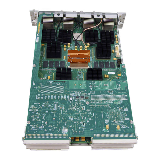
Page 47: Figure 5: Acquisition Board
Parts List Figure 5: Acquisition board TLA7Bxx Logic Analyzer Module Service Manual...
Need help?
Do you have a question about the TLA7B Series and is the answer not in the manual?
Questions and answers