Sign In
Upload
Manuals
Brands
Tektronix Manuals
Measuring Instruments
TLA7PG2
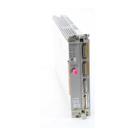
Tektronix TLA7PG2 Logic Analyzer Module Manuals
Manuals and User Guides for Tektronix TLA7PG2 Logic Analyzer Module. We have
6
Tektronix TLA7PG2 Logic Analyzer Module manuals available for free PDF download: Service Manual, Instruction Manual, Instructions Manual, Security Instructions
Tektronix TLA7PG2 Service Manual (253 pages)
Pattern Generator and Probes
Brand:
Tektronix
| Category:
Laboratory Equipment
| Size: 2 MB
Table of Contents
Table of Contents
8
Table 1- 1: PG Module Electrical Characteristics, Operational Mode
25
Table 1- 2: PG Module Electrical Characteristics, Output Pattern
25
Table 1- 3: PG Module, Internal Clock
26
Table 1- 4: PG Module, External Clock Input
26
Table 1- 5: PG Module, Event Processing
26
Table 1- 6: PG Module, Intermodule Interactions
27
Table 1- 8: PG Module, Mechanical
27
Table 1- 9: P6470 TTL/CMOS Probe
29
Table 1- 10: P6471 ECL Probe
32
Table 1- 11: P6472 PECL/LVPECL Probe
34
Table 1- 12: P6473 LVDS Probe
35
Table 1- 13: P6474 LVCMOS Probe
38
Table 1- 15: Power Supply (P6475 Only)
46
Table 1- 16: Atmospherics
46
Table 1- -17: Dynamics Characteristics (P6470, P6471, P6472, P6473, and P6474)
47
Table 1- 18: Dynamics Characteristics (P6475)
47
Table 1- 19: Probe Cables
47
Table 1- 20: Twisted Lead Set
47
Figure 1- 1: Clock and Strobe Timing Diagram
48
Figure 1- 2: P6470, P6472, P6473, and P6474 Inhibit Timing Diagram
48
Table 1- 21: Certifications and Compliances for P6475
48
Figure 1- 3: P6470, P6472, P6473, and P6474 External Event for Inhibit Timing Diagram
49
Figure 1- 4: External Event for Jump Timing Diagram
49
Figure 1- 5: External Event for Half Channel Advance Timing Diagram
49
Figure 1- 6: External Event for Full Channel Advance Timing Diagram
50
Figure 1- 7: External Event for Delay to Data Output for Advance Diagram
50
Table 1- 22: P6470 TTL/CMOS Probe and P6471 ECL Probe
50
Table 1- 23: Certifications and Compliances
51
P6475
59
Table 4- 1: Pattern Generator Module Verification Procedures
71
Table 4- 2: Test Equipment
74
Table 4- 3: Front Panel Indicators
77
Table 4- 4: Extended Diagnostic Test Items and Faulty Component
79
Figure 4- -1: Termination Board
84
Figure 4- -2: External Clock Input Connections Using a
84
Figure 4- 3: External Clock Input Connections Using a P6475
85
Figure 4- -4: Internal Clock Frequency Connections Using
88
Figure 4- -5: Internal Clock Frequency Connection Using
89
Figure 4- -6: Merge Operation Connections Using P6470
93
Figure 4- 7: Merge Operation Connections Using P6475 Probe
94
Figure 4- -8: Merged and Unmerged Modules in the Merge Modules Window
96
P6471, P6472, P6473, or P6474 Probes
97
Figure 4- 9: Timing Chart
97
Figure 4- 10: TLA7PG2 Deskew Function Connections Using a P6470, P6471, P6472. P6473, or P6474
98
Figure 4- 11: TLA7PG2 Deskew Function Connections Using a P6475 Probe
99
Figure 4- 12: TLA7PG2 Inhibit Function (by Data) Connections Using a P6470, P6473, or P6474 Probe
102
Figure 4- 13: TLA7PG2 Inhibit Function (by Data) Connections Using a P6475 Probe
102
Table 4- 5: Delay
182
Table 6- 1: Tools Required for Part Removal
191
Table 6- 2: P6470 Series Termination Resistors
199
Table 1- -14: P6475 Variable Probe
248
Advertisement
Tektronix TLA7PG2 Instruction Manual (66 pages)
Pattern Generator Probes
Brand:
Tektronix
| Category:
Portable Generator
| Size: 0 MB
Table of Contents
Table of Contents
6
General Safety Summary
10
Product Description
16
Figure 1: Standard Probe, Lead Sets, and Probe Cable
17
Probe Lead Sets and Cables
17
Figure 2: P6475 Variable Probe, Lead Sets, Power Cord
18
Connecting the Standard Probes
18
Connecting the P6475 Probe
19
Figure 3: P6470 and P6474 Output Connector Pin Assignments
22
Figure 4: P6471 Output Connector Pin Assignments
22
Probe Connectors and Signal Names
22
Figure 5: P6472 Output Connector Pin Assignments
23
Figure 6: P6473 Output Connector Pin Assignments
23
Figure 7: P6475 Output Connector Pin Assignments
23
Table 1: Inputs and Outputs of Pattern Generator Probes
24
Probe Overview
24
Figure 8: Strobe Output Pulse Pattern
26
Figure 9: P6475 Variable Probe Output Pulse Pattern
26
Figure 10: P6475 CH6 Output Example
27
Figure 11: P6475 CH6 Output Mode Pulse Patterns
28
Figure 12: P6470, P6471, P6472, P6473 and P6474
30
Probe Dimensions
30
Figure 13: P6475 Variable Probe Dimensions
31
Table 2: P6475 Variable Probe Installation Requirements
32
Input/Output Circuits
33
Figure 14: P6470 Input/Output Circuit
33
Figure 15: P6471 Input/Output Circuit
34
Figure 16: P6472 Input/Output Circuit
35
Figure 17: Signaling Sense
36
Figure 18: P6474 Input/Output Circuit
37
Figure 19: Clock and Strobe Timing Diagram
37
Timing Diagram
37
Figure 20: P6470, P6472, P6473, and P6474 Inhibit Timing Diagram
38
Figure 21: P6470, P6472, P6473, and P6474 External Event
38
Figure 22: External Event for Jump Timing Diagram
38
Figure 23: External Event for Half Channel Advance Timing Diagram
39
Table 3: P6470 TTL/CMOS Probe
40
Specifications
40
Table 4: P6471 ECL Probe
43
Table 5: P6472 PECL/LVPECL Probe
45
Table 6: P6473 LVDS Probe
46
Table 7: P6474 LVCMOS Probe
49
Table 8: P6475 Variable Probe
52
Table 9: Power Supply (P6475 Only)
57
Table 10: Atmospherics
57
Table 11: Dynamics Characteristics
57
Table 12: Dynamics Characteristics (P6475)
58
Table 13: Probe Cables
58
Table 14: Twisted Lead Set
58
Table 15: Certifications and Compliances for P6475
58
Functional Check
60
Figure 26: Removing the Standard Probe Cover
61
Figure 27: P6470 Series Termination Resistors
62
Table 16: P6470 Series Termination Resistors
62
Figure 28: P6474 Series Termination Resistors
63
Repackaging
64
Tektronix TLA7PG2 Instruction Manual (67 pages)
Pattern Generator Probes
Brand:
Tektronix
| Category:
Industrial Equipment
| Size: 3 MB
Table of Contents
Table of Contents
7
Figure 1: Standard Probe, Lead Sets, and Probe Cable
17
Figure 2: P6475 Variable Probe, Lead Sets, Power Cord, and Probe Cable
18
Figure 3: P6470 and P6474 Output Connector Pin Assignments
22
Figure 4: P6471 Output Connector Pin Assignments
22
Figure 5: P6472 Output Connector Pin Assignments
23
Figure 6: P6473 Output Connector Pin Assignments
23
Figure 7: P6475 Output Connector Pin Assignments
23
Table 1: Inputs and Outputs of Pattern Generator Probes
24
Figure 8: Strobe Output Pulse Pattern
26
Figure 9: P6475 Variable Probe Output Pulse Pattern
26
Figure 10: P6475 CH6 Output Example
27
Figure 11: P6475 CH6 Output Mode Pulse Patterns
28
Figure 12: P6470, P6471, P6472, P6473 and P6474
30
Probe Dimensions
30
Figure 13: P6475 Variable Probe Dimensions
31
Table 2: P6475 Variable Probe Installation Requirements
32
Figure 14: P6470 Input/Output Circuit
33
Figure 15: P6471 Input/Output Circuit
34
Figure 16: P6472 Input/Output Circuit
35
Figure 17: Signaling Sense
36
Figure 18: P6474 Input/Output Circuit
37
Figure 19: Clock and Strobe Timing Diagram
37
Figure 20: P6470, P6472, P6473, and P6474 Inhibit
38
Figure 21: P6470, P6472, P6473, and P6474 External Event
38
Figure 22: External Event for Jump Timing Diagram
38
Figure 23: External Event for Half Channel Advance
39
Table 3: P6470 TTL/CMOS Probe
40
Table 4: P6471 ECL Probe
43
Table 5: P6472 PECL/LVPECL Probe
45
Table 6: P6473 LVDS Probe
46
Table 7: P6474 LVCMOS Probe
49
Table 8: P6475 Variable Probe
52
Table 9: Power Supply (P6475 Only)
57
Table 10: Atmospherics
57
Table 11: Dynamics Characteristics (P6470, P6471, P6472, P6473, P6474)
57
Table 12: Dynamics Characteristics (P6475)
58
Table 13: Probe Cables
58
Table 14: Twisted Lead Set
58
Table 15: Certifications and Compliances for P6475
58
Table 16: P6470 Series Termination Resistors
62
Advertisement
Tektronix TLA7PG2 Instructions Manual (28 pages)
Pattern Generator Module
Brand:
Tektronix
| Category:
Control Unit
| Size: 0 MB
Table of Contents
Table of Contents
5
General Safety Summary
7
Preface
9
Related Documentation
9
Table I: Tektronix TLAPG2 Pattern Generator Module Documentation
9
Contacting Tektronix
10
Figure 1: Block Diagram of the Pattern Generator Module
11
Pattern Generator Module Introduction
11
Probes
11
Pattern Generator Program
11
Setting up the Pattern Generator Module
13
Module Setup Window
13
Figure 2: Module Setup Window
14
Figure 3: Channel Setup Window
14
Channel Setup Window
14
Figure 4: Probe Setup Window
15
Probe Setup Window
15
Signal Setup Window
15
Figure 5: Signals Setup Window
16
Figure 6: Block Definition Window
17
Setting up the Pattern Generator Program
17
Block Definition Window
17
Figure 7: Listing Window
18
Sequence Definition Window
18
Figure 8: Sequence Definition Window
19
Figure 9: Drag the Vertical Bar to the Left to Display the Sequence Flow Graphic
20
Figure 10: Sequence Flow Graphic
20
Figure 11: Subsequence Definition Window
21
Subsequence Definition Window
21
Event Definition Window
21
Figure 12: Event Definition Window
22
Table 1: PG Module Electrical Specification, Operational Mode
23
Appendix A: TLA7PG2 Pattern Generator Module Characteristics
23
Table 2: PG Module Clocking
24
Table 3: PG Module Event Processing
24
Table 4: PG Module Inter-Module Interactions
25
Table 5: PG Module Merged PG Modules
25
Table 6: PG Module Mechanical
25
Appendix B: Pattern Generator Physical-Logical Conversion
27
Table 7: for Signal 1, 2, and 3, 4, (Logical Function AND)
27
Table 8: for Signal 3, 4 (Logical Function OR)
27
Tektronix TLA7PG2 Instructions Manual (13 pages)
TLA700/TLA7000 Series Logic Analyzer
Brand:
Tektronix
| Category:
Measuring Instruments
| Size: 0 MB
Table of Contents
Table of Contents
3
Preface
5
Clear and Sanitize Procedures
7
Memory Devices
7
Data Export Devices
11
Troubleshooting
13
How to Sanitize or Clear a Nonfunctional Instrument
13
Tektronix TLA7PG2 Security Instructions (4 pages)
Logic Analyzer
Brand:
Tektronix
| Category:
Measuring Instruments
| Size: 0 MB
Table of Contents
Memory Erasure Procedure
3
Memory Parts
3
A20 Board P/N: 671-5063-50
3
A50 Board P/N: 671-4859-50
4
Advertisement
Related Products
Tektronix TLA7P2
Tektronix TLA7P4
Tektronix TLA7NA2
Tektronix TLA7E1
Tektronix TLA7AB4
Tektronix TLA 704
Tektronix TLA7S08
Tektronix TLA 7M3
Tektronix TLA 7M4
Tektronix TLA7NA Series
Tektronix Categories
Test Equipment
Measuring Instruments
Amplifier
Portable Generator
Printer
More Tektronix Manuals
Login
Sign In
OR
Sign in with Facebook
Sign in with Google
Upload manual
Upload from disk
Upload from URL