Table of Contents
Advertisement
Advertisement
Table of Contents

Related Manuals for Hanna Instruments PCA310


Summary of Contents for Hanna Instruments PCA310
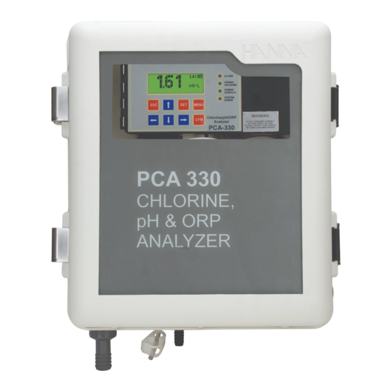
- Page 1 PCA310, PCA320, PCA330, PCA340 Chlorine, pH, Temperature, ORP Analyzers...
- Page 2 Free Chlorine and if it is set for total chlorine, the software will report at startup Total Chlorine. All rights are reserved. Reproduction in whole or in part is prohibited without the written consent of the copyright owner, Hanna Instruments Inc., Woonsocket, Rhode Island, 02895, USA.
-
Page 3: Table Of Contents
PRELIMINARY EXAMINATION....................GENERAL DESCRIPTION....................... MECHANICAL DIMENSIONS....................FUNCTIONAL DESCRIPTION....................DISPLAY, LEDS AND KEYPAD....................Display ......................LEDs ....................... Keypad ......................SPECIFICATIONS......................... OPERATING DESCRIPTION....................Chlorine measurement ..................Method of analysis ................... pH and temperature measurement ..............ORP measurement .................... INITIAL PREPARATION AND INSTALLATION................Installation Personnel.................. - Page 4 Modify a parameter ..................PROGRAMMING THE ANALYZER ..................SETTING RESTORE......................GENERAL SETTINGS ......................Changing the password ..................Setting the language ..................Analyzer serial number and software version ............Time and date ....................WORKING MODE ....................... Automatic mode ....................Standby mode ....................Manual mode ....................
- Page 5 pH CALIBRATION (PCA320, PCA330, PCA340) ..............One point calibration ..................Two-points calibration ..................Process pH calibration ..................Set default calibration ..................TEMPERATURE SETTINGS (PCA320, PCA330, PCA340) ............Units ....................... Measure info ....................Analog output....................Alarms ......................ORP SETTINGS (PCA330) ....................Measure info ....................
- Page 6 Modem connection..................... MAINTENANCE ........................Electrode conditioning and maintenance ............. Changing peristaltic pump tubing ............... Tubing replacement.................... Cleaning measurement cell ................. ERRORS, ALARMS AND WARNINGS ..................ACCESSORIES ........................
-
Page 7: Preliminary Examination
Note: Because of the inherent dangers in handling chemical samples, standards and reagents, HANNA Instruments strongly recommends the users of this product to review the Material Safety Data Sheets and become familiar with safe handling procedures and proper usage prior... -
Page 8: General Description
The Hanna Instruments PCA310, PCA320, PCA330 PCA340 series of chlorine, pH, ORP and temperature analyzers are microprocessor controlled, process analyzers which continuously monitor a sample stream for chlorine content, pH, ORP and temperature values. PCA310 PCA340 monitor the free chlorine or total chlorine in the 0.00 to 5.00 mg/L range depending on the factory settings and used reagents. - Page 9 Alarm condition controls a SPDT relay. A system error feature provides relay activation to signals need for operator intervention. System error condition controls a SPST relay. PCA310 PCA330 series the voltage output ranges of 0-10 mV, 0-100 mV, 0-1 V or a current output of 4-20 or 0-20 mA are available to drive an external device such as a chart recorder.
-
Page 10: Mechanical Dimensions
Time is displayed on the main panel and a time related warning system for “Old calibration”, “Reagent expired” and “SIM expired” is available. The language for user interface can be easily changed without restarting the analyzer. Case dimensions in mm & inches... -
Page 11: Functional Description
WARNING IF ANY CONDENSED HUMIDITY IS FOUND INSIDE THE CASE PLEASE CONTACT YOUR VENDOR OR HANNA CUSTOMER SERVICE. 13. Pressure Regulator Output Port 1. Alarms, dosing, system error LED’s 14. Incoming Pressure Regulator 2. Character Display 15. Buffer Bottle 3. Cable glands 16. -
Page 12: Display, Leds And Keypad
The analyzer is in main panels mode when displays a panel that contains the measured values. Several main panels could be selected by pressing the up and down arrow keys. The PCA310 do not have the main mode for the display. -
Page 13: Leds
CHLORINE of the System error relay. When the error is present, the LED blinks. When in SYSTEM STANDBY mode, the led is on but not blinking. ERROR PCA310 the system error LED is moved in the dosing ACID/ALK. LED position. -
Page 14: Keypad
KEYPAD The keypad has 8 keys with the following signification: UP and DOWN ARROWS • select the main display appearance, • select the menu, • select an item from a list, • edit values. LEFT and RIGHT ARROWS • select an error message, •... -
Page 15: Specifications
CHLORINE MEASUREMENT AND DOSING (All models) Range 0.00 to 5.00 mg/L Resolution 0.01 mg/L Accuracy ± 8% or ± 0.05 mg/L whichever is greater Calibration 1 point Minimum detectable level 0.05 mg/L Sampling rate adjustable from 3 to 90 minutes Dosage proportional relay or 4-20 mA output Delta (∆) - Page 16 Resolution 0.1 °C (0.1 °F) Accuracy ± 0.5 °C (± 1.0 °F) OTHERS (All models) 0-10 mV, 0-100 mV, 0-1 V, 4-20 mA, 0-20 mA (PCA310, Recorder output PCA320, PCA330) 4-20 mA, 0-20 mA (PCA340) Serial communication RS485, galvanic separated Baud rate 1200;...
-
Page 17: Operating Description
Drain connection 10 mm ( ”) barb Process pH/temp probe HI1005 Process ORP probe HI2008 115 VAC ± 10% or 230 VAC ± 10%; Power supply 50-60 Hz; 20 VA Case NEMA-4X CHLORINE MEASUREMENT Referring to the drawing on page 11 and the Fluidic Diagram on page 18, the Sample Line is connected to the instrument at the Sample Port (#17);... -
Page 18: Method Of Analysis
After a delay for the color development, a series of measurements (with LED on and off) are taken (sample level) to determine an average chlorine concentration measurement. The reacted sample signal is then measured and displayed. This sequence is repeated every 3 to 90 minutes (user-selectable). METHOD OF ANALYSIS Free available chlorine oxidizes the DPD indicator reagent at a pH between 5.5 and... -
Page 19: Initial Preparation And Installation
Hanna Instruments assumes that persons performing the installation tasks are aware of the appropriate safety procedures. CAUTION: Review the Material Safety Data Sheets (MSDS) before handling the supplied chemical reagents. - Page 20 BSP sample input fitting allows direct connection to the optional input filter. Sample line pressure should be between 0.07 and 4 bar (1 and 57.2 psi) with an ideal pressure of 0.7 bar (10 psi). It is recommended to assure that the water inlet come at 1 m above the instrument sample input pitting.
-
Page 21: Installing The Input Filter
Return Line Installation The return hose fitting is a 12 mm ( ”) hose barb on the bottom of the regulator output port and should always be connected even when pressure is below 1 bar. INSTALLING THE INPUT FILTER In order to ensure maximum accuracy of measurements, it is recommended to have always clear sample, with suspended particles smaller than 0.5 µm. -
Page 22: Installing The Pump Tubes
Screw the pH probe (HI1005) in the lower position and the ORP probe (HI2008) in the higher position and assure that no leakage occurs. Only after the probe is in final position connect the probe to the dedicated connector. Lock the connector with the built in nut. -
Page 23: Electrical Connections
Place the indicator bottle (HI70450 for free chlorine and HI70460 for total chlorine) on the right and the buffer bottle (HI70451 for free chlorine and HI70461 for total chlorine) on the left. Note: Add the content of 5 HI70452 sachets, DPD Compound, to the Indicator Solution prior to installing it. - Page 24 Hard wiring with 13 mm ( ”) conduit is recommended and usually required by most municipal electrical codes. Warning: For PCA310 PCA340 before connecting the instrument to the line: 1) Check the label near the fuses for proper voltage. 2) Be sure the power cord is not connected to the line.
- Page 25 Recorder Output and Relay Access Hard wiring for alarms and relays recorder output and serial communication can be accomplished through four watertight connectors on the left side of the enclosure, by passing wires through the rubber grommet and tightening the nut as described earlier. Refer to the drawings for proper wire connections.
- Page 26 To operate with this hookup, the following conditions are required at the recorder end: • The input to the recorder must be isolated from the chassis ground (earth) of the recorder; • If the recorder has more than one input, they must be differential inputs. For PCA310, PCA320 PCA330 several type of outputs are available: 0-10 mV, 0-100 mV, 0-1 V, 0-20 mA or 4-20 mA.
- Page 27 0-20 mA or 4-20 mA for each output. The recorder outputs could be assigned to Cl, pH, Temperature.(see the right figure) Proportional dosing pump At PCA310, PCA320 PCA330 a proportional dosing pump could be connected to the 4-20 mA output.
-
Page 28: Startup
After initialization, the analyzer will show the main panel (or chlorine measuring panel for PCA310 and PCA340). The measured value are displayed. The chlorine concentration will be updated only after a full measuring cycle. The first reading is 0.00 mg/L and the dosing relay is not active. -
Page 29: User Interface
PANELS ORGANIZATION PCA310 PCA340 analyzers provide a friendly interface that display all important parameters of the analyzer. The appearance of the display could be selected by the user. The panels are organized in circular loops. PCA330 has a main loop where panels with all measurements... -
Page 30: Measure Panels
Example: When pH is displayed on the left side and the chlorine, ORP and temperature on the right side, pressing CFM will go in one of the pH measure panels. MEASURE PANELS For each parameter, several measure panels are available. One panel contains large digits for better visibility. -
Page 31: Messages
The display go in large digits panel if no key is pressed for about 4 minutes. If key is pressed, the display returns in the panel where it was before. Pressing ESC when in one of those panels will return in main panels mode. 16:49 mg/L MESSAGES... -
Page 32: Navigating Through Menu
If correct password is entered and confirmed, the analyzer will go in menu mode. If wrong password is entered, the analyzer displays “Password incorrect. Settings are not allowed!”, and the user could only view the analyzer parameters. NAVIGATING THROUGH MENU The menu is organized as a list of options. - Page 33 For list type parameter In this case the cursor will blink and first letter alternates with a black square. To modify the value press up or down arrow key until the correct value appears. Setpoint :2.50 mg/L Delta :0.1 mg/L Low Point:0.02 mg/L Low Point:Inactive Press CFM to save the value or press ESC to end the editing without saving the value.
-
Page 34: Programming The Analyzer
Select the appropriate entry as described in next pages. The settings are stored in a nonvolatile EEPROM memory. If a power failure appears the settings are restored after power on. When power is first time applied to PCA310 PCA340 analyzers, the settings are set to factory default values. -
Page 35: General Settings
+ SET + MENU pressed while the instrument is powered on. The analyzer settings, common for all measurements, are grouped in “General Menu”. For PCA310, PCA320 and PCA330, is availble only one setiing area as showed in the right picture. -
Page 36: Changing The Password
Press CFM to save. After new value is confirmed, the displayed password is set to 0000 for protection against unauthorized reading. SETTING THE LANGUAGE PCA310 PCA340 analyzers has 4 languages stored inside. The user could easily change the language without restarting the analyzer. -
Page 37: Working Mode
Three working modes could be selected for the analyzer. The selection is available in “General Menu” - “System Functions” - “Manual Commands” - “Work Mode”. The work mode could be set as AUTOMATIC, STANDBY or MANUAL. Work Mode:AUTOMATIC Read On Demand Alarm Relay :ON Dose Cl Rel :ON Dose pH Rel :ON... -
Page 38: Read On Demand
The display will show “MANUAL” on the first line when in the measurement panels. The displayed values will be the last measured ones and the measuring sequence is stopped. When in manual mode the ALARM LED is always on (no blinking). READ ON DEMAND When this function is selected, (“General Menu”... -
Page 39: Chlorine Settings
The settings related to chlorine measurement are grouped in “Chlorine Menu”. The following options are available: REAGENT CHANGING One set of reagents is enough for at least 16000 samples. The remaining doses of reagent are displayed on one chlorine measuring panel. When the reagent is changed, several actions must be performed: Prepare the reagent and install the new bottles as described in initial preparation and installation chapter. -
Page 40: Measure Settings
MEASURE SETTINGS Select “Chlorine Menu” - “Measure Settings” and set the “Period” between 3 and 90 minutes. Period (sampling rate) is the elapsed time between two consecutive chlorine measurements. The sampling rate is also important when the analyzer is used for chlorine dosing. For larger pools, the period must be longer, and for smaller pools, the period must be shorter. -
Page 41: Chlorine Dosing
The output will be proportional with chlorine if the read value is between those limits. Example: For PCA310 PCA330 if the 0.0 to 1.0 V recorder output has been selected, the operator can select 0.0 V to correspond to a concentration of 3.00 mg/L (Min. Rec. setting) and 1.0 V to correspond to a concentration of 4.50 mg/L (Max. - Page 42 Example: For setpoint 3.00 mg/L, delta=0.5, sample rate 5 minutes and measured value 2.80 mg/L, the proportional dosing will be active for the initial 2 minutes and will stop for the remaining 3 minutes. In fact: Time = (3-2.8)*5/0.5 = 2 minutes Analog output = 4 + 16*2/5 = 10.4 mA To modify the dosing setpoint, enter the “Chlorine Menu”...
-
Page 43: Alarms
ALARMS Two alarm setpoints are available for chlorine: Alarm high and Alarm low. The ALARM LED and alarm relay are activated when the chlorine concentration is higher than Alarm high or lower than Alarm low. To modify the alarm setpoints, enter the “Chlorine Menu” - “Alarms & Err Chlorine” and edit “Alarm Hi”... -
Page 44: Calibrate The Measuring Cell
PCA310 PCA340 analyzers have the possibility to calibrate the measuring cell. When a new calibration is performed, calibration factor is recalculated and all measurements are multiplied with it. CALIBRATION DATE AND FACTOR The last calibration date can be found in the “Chlorine menu” - “Cal. Measuring Cell” - “Cal. Date”. -
Page 45: Ph Settings (Pca320, Pca330, Pca340)
• Press repeatedly ESC to exit from menu mode. The displayed chlorine concentration will be equal with the calibration value. Note: It is not recommended to calibrate the analyzer at values below 2 mg/L in order to maintain enough accuracy in the whole range. Calibration below 2 mg/L does not guarantee declared accuracy outside an interval of ±50% from the calibration value. -
Page 46: Analog Output
ANALOG OUTPUT The type of analog output could be set as described in “Analog output” chapter. The analog output span for pH could be set in “pH Menu” - “Analog Output pH”. “Min. Rec” will set the recorder low limit and “Max. Rec” will set the recorder high limit. The Max. Rec. - Page 47 The equation for determining the time for relay on is: dosing time = (set value - measured value)*Period/Delta The analog output will have the value: analog output [mA] = 4 + 16 * dosing time/Period [mA] Note: If the measured pH is lower (or higher for acid dosing) than setpoint minus (plus) delta, the dosing will be continuous until the pH period elapsed.
-
Page 48: Alarms
Overdosing protection To prevent overdosing a “Detector Error” is generated if the dosing command is on for the “Max. ON“ time and the read value is changing less than pH 0.1. The acid/alkali dosing is stopped and the SYSTEM ERROR LED starts blinking. The dosing could be resumed only by restarting the controller. -
Page 49: Ph Calibration (Pca320, Pca330, Pca340)
It is recommended to perform pH calibration when the probe is replaced and after any cleaning action. The analyzer can perform 2 points calibration, 1 point calibration or process pH calibration. To perform any pH calibration enter in “pH Menu” - “Cal. pH Probe”. Set Default pH Cal. -
Page 50: Two-Points Calibration
Note: If the read value, calculated with the default offset and slope, is different from the expected value with more than 1.15 pH (i.e. offset > 68 mV), the “Wrong calib. values” message is displayed. The message “Wrong calib. values” appears also if the pH probe is defective or not connected. The problem could be identified if the buffer set value is compared with the actual read value (first and second line of the display). -
Page 51: Process Ph Calibration
PROCESS pH CALIBRATION The PCA320, PCA330 PCA340 has the possibility to calibrate the pH probe without using buffers and without dismount the probe. For doing this calibration, a reference pH-meter must be used. To complete the process calibration, follow the steps: •... -
Page 52: Temperature Settings (Pca320, Pca330, Pca340)
Settings related to temperature measurement are grouped in “Temperature Menu”. The following options are available: UNITS The analyzer could display the Temperature using Celsius or Fahrenheit temperature units. To select the temperature units, edit the “Temperature Menu” - “Units” line. Select Celsius or Fahrenheit and confirm. -
Page 53: Alarms
“Min. Rec” will set the recorder lower limit and “Max. Rec” will set the recorder higher limit. The Max. Rec. value must be greater than Min. Rec. value. The output will be proportional with temperature value if the read value is between those limits. The analog output limits could be quickly consulted in one of the Temperature measuring panel. -
Page 54: Orp Settings (Pca330)
Settings related to ORP measurement are grouped in “ORP Menu”. The following options are available: Alarms ORP Analog Output ORP Measure Info MEASURE INFO The analyzer calculates the maximum and minimum ORP value since the first measurement. The maximum and minimum can be quickly consulted on one ORP measuring panel. For more detailed information select “ORP Menu”... -
Page 55: Alarms
ALARMS Two alarm setpoints are available for ORP: Alarm high and Alarm low. The ALARM LED and relay are activated when the ORP value is higher than Alarm high or lower than Alarm low. To modify the alarms setpoints, enter the “ORP Menu”-“Alarms ORP” menu and edit “Alarm Hi” value or “Alarm Lo”... -
Page 56: Analog Output
PCA340, “Chlorine”, “pH”, “ORP” and “Temper.” for PCA330. To select the analog output type edit the “Type” line. The available options are: 0-10 mV, 0-100 mV, 0-1 V voltage outputs and 0-20 mA , 4-20 mA current outputs for PCA310, PCA320, PCA330 and 0-20 mA , 4-20 mA current outputs for PCA340. -
Page 57: Calibrate The Analog Output
0V. • Save the new coefficients by pressing CFM key. RECORDER To calibrate the current type analog outputs, follow the steps: • For PCA310, PCA320 PCA330 connect an ammeter to the pin 2 and 3 of the output connector. -
Page 58: Output Middle Range
Note: The analog output calibration is not allowed if the analog output type is set to “Dosing”. Pressing for longer time the arrow keys will increase the variation speed of the analog output. PCA310 PCA340 analyzers have a permanent logging function. Up to 3500 records could be stored. -
Page 59: Clear System Log
CLEAR SYSTEM LOG To erase the system log activate the function “General Menu” - “System Log” - “Clear System Log”. VIEW LOG To consult the log, select “General Menu” - “System Log”. The searching criteria for viewing the log could be set by editing the “Search” field. The following options are available: •... - Page 60 The records will have the following structure: 14:38 1.00 5.86 14:33 1.05 5.63 A 14:27 1.20 4.99 14:22 1.17 5.11 AE 1 - Time of the record 2 - Chlorine value 3 - pH value (only for PCA320, PCA330, PCA340) 4 - Alarm field (empty if no alarms) 5 –...
-
Page 61: Serial Communication
If many errors or alarms are present, the “<” and “>” signs are displayed on the left or right side of the display. Selecting another message could be done by pressing left or right arrow keys. Pressing three time ESC will return in the main menu. PCA310 PCA340 have one RS485 serial communication port. The serial communication is galvanically isolated from other analyzer parts. -
Page 62: Gsm
GSM MODE If the “Type” is set to GSM, the analyzer will work with HI504900 GSM module. This connection enables the analyzer to send SMSs to one (or two) cellular phone(s) and through this feature the device can be monitored. Moreover if an error occurs on the PCA3x0, a SMS is sent to the cellular phone(s) signaling immediately the user about the problem. -
Page 63: Gsm Connection
Example: if the cellular number is +39123456789 (+39 is the country code), the number to be stored in the PCA310 PCA340 is 39123456789. The numbers could be activated or inactivated. The SMS is sent only to active numbers. If both numbers are inactive, no SMS is sent even if both numbers are correctly entered. -
Page 64: Setting Sms Feature
SETTING SMS FEATURE In order to avoid the frequent sending of the SMSs or rapid consuming of the GSM credit when one measuring channel not work correctly, the SMS sending could be customized. The options are available in the “General Menu” - “SMS Settings”. To select the events that generate alarm SMS, set the “Cl Events”, “pH Events”, “ORP Events”... - Page 65 In this case a message header is added with informations about the message type and the current / total number of SMSs (for example INF1/2: ). It is possible to ask the PCA310 PCA340 for Info SMS from a cellular phone different from the one(s) set in the analyzer.
- Page 66 Example of info SMS (splitted): “INF1/2: Temp Err; L Cl; L Ph; H Temp; Cl Cal; SET: Cl (SP=2.00; AIH=2.70; AIL=150); pH(SP=7.00; AIH=8.00; AIL=6.00); ORP (AIH=800; AIL=200); Temp (AIH=30.0; AIL=20.0);” “INF2/2: READINGS: ReagRem=8413;Cl=1.35;pH=5.02; ORP=280; Temp=75.0; Remaining SMS=321;” Warning SMS The information about SIM charge and expiration date are not saved in the SIM card but are managed by the network operator;...
-
Page 67: Modem Connection
The error will be deactivated only after a successful initialization. MODEM CONNECTION Modem connection can be established between PCA310 PCA340 and a remote computer. The connection allows the user to interrogate the analyzer, from remote position, about its status and measurements and to change analyzer parameters. -
Page 68: Maintenance
The PCA310, PCA320, PCA330 PCA340 analyzers incorporate several technologies to minimize the maintenance. Also, if the GSM module is connected, the warnings, alarms and errors are sent to the operator, making the maintenance even simpler. The analyzer status could be sent via SMS messages after a call from operator. - Page 69 Rinse the probe tip with distilled water. Immerse the probe in the Hanna Instruments pH buffer 7.01 (HI7007) until the solution is in contact with the metal ring and stirr gently for 30 seconds. The reading must be near pH 7.01. Repeat the operation for pH 4.01 solution (HI7004).
-
Page 70: Changing Peristaltic Pump Tubing
1 hour. Check to make sure the installation is such as to create a well for the probe bulb to constantly remain moist. • Drifting: soak the probe tip in warm Hanna Instruments Solution HI7082 for one hour and rinse tip with distilled water. -
Page 71: Tubing Replacement
Remove the reagent tubing from one end of the pump tube fitting and pull the pump tube from behind the pump rollers. Replace the pump tube with a new one and reassemble in reverse order. Repeat for the other pump tube. TUBING REPLACEMENT The remaining tubing in the analyzers should be replaced every two months. -
Page 72: Cleaning Measurement Cell
CHANGING MEASURMENT CELL To change the measuring cell (#8 page 11) with a new one (HI704871) in the PCA310 PCA340 analyzers, follow the steps: • Stop the analyser by turning off the main switch. -
Page 73: Errors, Alarms And Warnings
• If the message “failed” appears, the cell is not working properly. Check the electrical cable connection and if the error persist contact your local Hanna Instruments Office. • Prime the reagent pump - see page 41 for details. - Page 74 “Detector Error” on LCD and “Det Err” on SMS This error appear in the following situation: The light do not reach the detector. The light source is broken or the cell inner wall is dirty. The light that reach the detector with lamp off is too high. The light source circuit or the detector circuit is broken.
- Page 75 Change the setpoint, verify the chlorine dosing, wait for PCA to adjust the value. “High pH” on LCD and “H pH” on SMS The pH is over the Alarm High setpoint. Change the setpoint; verify the pH dosing; verify if acid/base dosing is correctly set; wait for PCA to stabilize the value.
- Page 76 “Reagent Expired” on LCD and “Reag Exp” on SMS Reagent is older than 3 month. The reagent expiration time is started when reagent counter is reset or “prime reagent pump command is executed. Change the reagent and reset the reagent counter. “GSM Wrong PIN Code”: appears on LCD Wrong PIN code was entered.
-
Page 77: Accessories
“No ORP Calibration” on LCD and “No ORP Cal” on SMS The ORP channel was not calibrated. Appears after EEPROM error. Contact your local Hanna Instruments Office. “No Temp. Cal” on LCD and “No T Cal” on SMS The Temperature channel was not calibrated. - Page 78 HI70487 Colorimetric cell HI70488 Electrovalve (24Vac/60Hz) HI70489 Electrovalve (24Vac/50Hz) HI70492 Electrode holder PCA330 HI70493 Closing cap for electrode holder HI70494 Calibration port tap HI70496 Replacement filter 0.45um (1 pcs.) HI70497 Replacement filter 50um (1 pcs.) pH Solutions HI7004M or HI7004L pH 4.01 Buffer Solution, 230 or 500 mL bottle HI7006M or HI7006L pH 6.86 Buffer Solution, 230 or 500 mL bottle...
- Page 79 Returned Goods Authorization (RGA) number from the Technical Service department and then send it with shipping costs prepaid. When shipping any instrument, make sure it is properly packed for complete protection. Hanna Instruments reserves the right to modify the design, construction or appearance of its products without advance notice.
- Page 80 World Headquarters Hanna Instruments Inc. Highland Industrial Park 584 Park East Drive Woonsocket, RI 02895 USA www.hannainst.com Local Office Hanna Instruments USA 270 George Washington Highway Smithfield, RI 02917 Phone: 800.426.6287 Fax: 401.765.7575 e-mail: tech@hannainst.com MANPCA Printed in ROMANIA...
Need help?
Do you have a question about the PCA310 and is the answer not in the manual?
Questions and answers