Advertisement
Quick Links
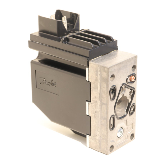
Installation Guide
Electrical Actuating Module
PVE series 4 for PVG 32 and PVG 100
PVE for PVG 32 and PVG 100:
Oliestrømmens retning for
standard monterede grupper.
Oil flow direction for standard
assembled groups.
Richtung des Ölstroms für
Standard-Baugruppen.
Sens du débit pour ensembles
standard.
For Technical Information, see Danfoss.com.
Mounting PVE
Instruktionen dækker
Instruction covers
Anleitung umfasst
l'instruction couvre
Danfoss actuators PVEA, PVEH, PVEM, PVEO, PVEP,
PVES, PVEU Variants -R, -DI, -SP, -F.
Connectors Deutsch, AMP, DIN/Hirschmann.
For full documentation see
Series 4 for PVG 32, PVG 100 and PVG 120,
www. Danfoss.com
• Protect LVDT-pin if present
• Ensure O-rings are in place
• Ensure gasket when using AMP and DIN/Hirschmann connector
• Do not over torque
WWarning
PVEA is not for use on PVG 100.
© Danfoss, 2014-03
Technical Information, PVE
520L0553 on
520L0619 • Rev EB • Mar 2014
to application
to tank
8 ±0.5 N•m
[70 ±4.4 lbf•in]
5 [0.2]
V310115.A
P→A
V310348A
157-743.10B
1
Advertisement

Related Manuals for Danfoss PVE 4 Series


Summary of Contents for Danfoss PVE 4 Series
- Page 1 Mounting PVE Instruktionen dækker Instruction covers Anleitung umfasst l'instruction couvre Danfoss actuators PVEA, PVEH, PVEM, PVEO, PVEP, PVES, PVEU Variants -R, -DI, -SP, -F. Connectors Deutsch, AMP, DIN/Hirschmann. For full documentation see Technical Information, PVE Series 4 for PVG 32, PVG 100 and PVG 120, 520L0553 on www.
- Page 2 • U alimente les électrodistributeurs Les deux bornes masse sont reliées intéreurement. L’emploi de deux sources d’alimentation séparées a des avantages, voir Information Technique pour PVE série 4 520L0619 • Rev EB • Mar 2014 © Danfoss, 2014-03...
- Page 3 DI-A y Ground pins are internally connected. DI-B only supplies electronics for feedback signal and error pin on PVEA-DI / PVEH-DI. Two separate power sources can be used. P301 105 © Danfoss, 2014-03 520L0619 • Rev EB • Mar 2014...
- Page 4 ) for standard mounted PVEP Function PWM A PWM B Neutral < 10% < 10% Q: P → A 10% → 80% < 10% Q: P → B 10% → 80% < 10% 520L0619 • Rev EB • Mar 2014 © Danfoss, 2014-03...
- Page 5 Maximum load of “DI-A” , “DI-B” 50 mA Voltage U high by load 20 mA > U –1.5 V Voltage U high by load 50 mA > U –2.0 V Voltage low < 0.2 V © Danfoss, 2014-03 520L0619 • Rev EB • Mar 2014...
- Page 6 NB: In particularly exposed applications, protection by screen is recommended. Remarque: Pour les applications particulièrement exposées, il est recommandé * According to the international standard IEC 529. d’installer une protection par écran. 520L0619 • Rev EB • Mar 2014 © Danfoss, 2014-03...
- Page 7 – peut être fait par exemple sur la base de la norme EN 954-1 (parties du système de commande relatives à la sécurité). Se reporter également à Information technique pour PVE série 4. © Danfoss, 2014-03 520L0619 • Rev EB • Mar 2014...
- Page 8 11007513 4 pin white blue yellow — — 157B4994 6 pin white black yellow green blue 157B4974 AMP/black coding 4 pin white blue yellow — — 157B4995 520L0619 • Rev EB • Mar 2014 © Danfoss, 2014-03...