Paradox Magellan MG5050 Programming Manual
32 zone wireless transceiver security systems, 4 to 32 zone expandable security systems
Hide thumbs
Also See for Magellan MG5050:
- Programming manual (76 pages) ,
- Programming steps (3 pages) ,
- Reference & installation manual (69 pages)

Related Manuals for Paradox Magellan MG5050


Summary of Contents for Paradox Magellan MG5050
- Page 1 32 Zone Wireless Transceiver Security Systems MG5000 V4.5 MG5050 V4.5 4 to 32 Zone Expandable Security Systems SP4000 V4.5 SP5500 V4.5 SP6000 V4.5 SP7000 V4.5 Always Armed, Never Disarmed Programming Guide PARADOX.COM...
- Page 2 Limitations of Alarm Systems: It must be understood that while your Paradox alarm system is highly advanced and secure, it does not offer any guaranteed protection against burglary, fire or other emergency (fire and emergency options are only available on certain Paradox models). This is due to a number of reasons, including by not limited to inadequate or improper installation/ positioning, sensor limitations, battery performance, wireless signal interruption, inadequate maintenance or the potential for the system or telephone lines to be compromised or circumvented.
-
Page 3: Table Of Contents
Min. = 61mA / Max. = 143mA Wireless Receiver (Spectra SP only) Min. = 26mA / Max. = 61mA PCS200 Paradox Communicator Module Min. = 80mA / Max. = 600mA Important System Notes Please refer to the following module compatibility exceptions to ensure proper system function: •... -
Page 4: Comparison Chart
*** When used with an SP4000 system, the RTX3 only allows for the use of remote controls. † When used with an SP4000 system, the RX1 only allows for the use of one-way remote controls. ‡ For compatible BabyWare version, refer to paradox.com. Programming Guide... -
Page 5: Specifications
Specifications MG5000 / MG5050 Power rating 16.5 VAC (50 or 60Hz) minimum 20 VA (40 VA recommended) Aux. power 600 mA typical, 700 mA maximum, fuseless shutdown at 1.1A Battery 12 VDC, 4Ah/7Ah Battery charging current 350 mA On-board zones MG5000: 2 MG5050: 5 Bell output... -
Page 6: Data Entry & Display
Data Entry & Display To access the Data Display Mode, press the [ ] key after entering a section and before entering any data. The four LEDs/Icon as ENTER indicated below will begin to flash indicating that you are in the Data Display Mode. K636 K10V/H K32RF/K32... -
Page 7: System Codes
System Codes The Installer code is used to enter programming mode, which allows you to program Installer Code (Default: 0000 / 000000) everything except user codes. To change the default code, go to section [397] on page 50 and refer to section [701] option [1] on page 50. The Maintenance code is used to enter programming mode, which allows you to program everything except for user codes and communication settings (sections Maintenance Code (No Default) -
Page 8: System Planning
System Planning Bus Module Planning Use the following table to plan wired keypads, RTX3, RX1, ZX8 and ZX8SP modules. Path Zone* Serial # Sticker Description Path Zone Path Zone Path Zone (Entry Point) Bus Module 1 Bus Module 2 Bus Module 3 Bus Module 4 Bus Module 5 Bus Module 6... - Page 9 Wireless Keypad Planning Path Zone Serial # Sticker Description Path Zone Path Zone Path Zone (Entry Point) K32RF / K37 1 K32RF / K37 2 K32RF / K37 3 K32RF / K37 4 K32RF / K37 5 K32RF / K37 6 K32RF / K37 7 K32RF / K37 8 NOTE: When deleting a wireless keypad (K32RF / K37) from the system, the corresponding StayD path zones will also be deleted.
- Page 10 PGM Planning Serial # Sticker Description Serial # Sticker Description PGM 1 PGM 9 PGM 2 PGM 10 PGM 3 PGM 11 PGM 4 PGM 12 PGM 5 PGM 13 PGM 6 PGM 14 PGM 7 PGM 15 PGM 8 PGM 16 Wireless Repeater Planning Serial # Sticker...
- Page 11 Armed when... Armed when... Serial # Sticker Zone# Zone Description Stay Sleep Full Serial # Sticker Zone# Zone Description Stay Sleep Full Zone Zone Zone Zone ...
-
Page 12: Zone Programming
Zone Programming See Quick Menus on page 65 NOTE: For keypad zone programming, see page 18. Zone Recognition (MG Series) When expanding zones via ZX8, up to 3 ZX8 modules can be added to the system and are identified by the ZX8 3-position jumpers +1, +9 and +17. - Page 13 SP4000 No ATZ SP4000 ATZ SP5500 No ATZ SP5500 ATZ Zone 18: Input 6 Zone 18: Input 2 Panel + 9 Zone 18: Input 5 Zone 18: Input 8 Zone 19: Input 7 Zone 19: Input 3 Zone 19: Input 6 Zone 19: Input 1 Zone 20: Input 8 Jumper Zone 20: Input 4...
- Page 14 Zone Definitions NOTE: If a zone is already programmed and you assign a device to the same zone, a wireless zone will overwrite a keypad/hardwire zone, and a keypad zone will overwrite a hardwire zone. To program zone definitions, zone partitions and assign options: Step Action Details...
- Page 15 Custom Zone Definitions Create up to four custom zone definition templates* (custom zone definition templates [033] to [036] will overwrite zone definitions 33 to 36, refer to the Zone Definitions table on page 14). Modifications can be made according to the Permitted Zone Definitions table below. Section Disarm Stay Arm...
- Page 16 Zone Labels [965] Reset Zone Labels Option Enabled Reset zone labels* Disabled * Ensure all other options are deselected. Press [ ] to reset the respective set of labels to default before exiting the section. ENTER Section Zone Label Section Zone Label [181] __/__/__/__/__/__/__/__/__/__/__/__/__/__/__/__ [197]...
- Page 17 [6] & [7] Supervision Options RF Zone Supervision Options (except SP4000) Keypad / Bus Module Supervision Options Disabled Disabled Trouble only Trouble only When disarmed: Trouble only Trouble only When armed: Follow zone’s alarm type When disarmed: audible alarm Trouble only When armed: Follow zone’s alarm type ...
-
Page 18: Keypad Programming
Zone Report Codes (Default = FF) [966] Clear Zone Report Codes Option Enabled Clear zone report codes* Disabled * Ensure all other options are deselected. Press [ ] to clear the respective set of report codes before exiting the section. ENTER [967] Reset Zone Report Codes... -
Page 19: Partition Programming
[701] Keypad Options 1 Option Confidential mode Disabled Enabled To exit confidential mode Enter a code Press a key 2 minutes Confidential mode timer 5 seconds Enabled Display entry delay on LCD keypad (K32LCD) Disabled ... -
Page 20: System Programming
[742] Partition 2 Options Option Auto-arm on time Disabled Enabled Auto-arm on no movement Disabled Enabled Auto-arm arming mode See Table See Table [3]&[4] Regular Sleep Stay Switch to stay arming if no entry delay zone is opened Disabled Enabled ... -
Page 21: Daylight Savings Programming
System Timers Section Data Description [710] ____/____/____ (000 to 255) seconds Entry delay 1 (default 045) [711] ____/____/____ (000 to 255) seconds Entry delay 2 (default 045) [712] ____/____/____ (000 to 015) Auto zone shutdown counter (default 005) [713] ____/____/____ (000 to 255) seconds Intellizone delay (default 048) [714]... -
Page 22: Communication Programming
Communication Programming The Communication Programming section is divided into sections corresponding to each installation type. Begin by programming the General Communications Options, and then program for one or more of the following specific installation types: • Landline - see page 24 •... - Page 23 [803] Event Call Direction Options 2 Option Enabled Call tel. #1 / monitoring rcvr. #1 for tamper/restore report codes Disabled Enabled Call tel. #2 / monitoring rcvr. #2 for tamper/restore report codes Disabled Call pager for tamper/restore report codes Disabled Enabled...
- Page 24 VDMP3 Options [703] Arm/disarm with VDMP3 Option Enabled Arm/disarm with VDMP3 Disabled Section Data Description [841] ____/____/____ (000 to 032) Maximum voice dialing attempts - VDMP3 (default 008) NOTE: For more VDMP3 options, see Communication Timers on page 23. Landline Communication Panels can be programmed for landline reporting using the following sections: [800]...
- Page 25 GSM Communication Systems that include the PCS Series (GSM) can be programmed for GSM communication using the following sections: [800] Reporting Option Dialer activated Reporting* Dialer deactivated * This option also applies to landline communication. Section Data [815]* ___/___/___/___/___/___/___/___/___/___/___/___/___/___/___/___/___/___/___/___/___/___/___/___/___/___/ MONITORING STATION TELEPHONE NUMBER [816]*...
- Page 26 PCS Series (GSM) Settings Section Data Description [855] ___/___/___ (000 to 255) x 2 seconds GSM no service timer (default 016) [856] ___/___/___ (000 to 255) SMS language (default 000) Table 6: SMS Language ID Language Language Language Language English Portuguese Croatian Slovak...
- Page 27 IP Receiver 1 Configuration [929] ___/___/___ . ___/___/___ . ___/___/___ . ___/___/___ . 100.100.100.100) “0” IP ADDRESS WAN NOTE DIGIT NUMBERS S BEFORE THE FIRST DIGIT [930] ___/___/___/___/___ . 10000) IP PORT WAN [931] ___/___/___ . ___/___/___ . ___/___/___ . ___/___/___ IP ADDRESS WAN [932] ___/___/___/___/___...
- Page 28 Table 7: IP/GPRS Registration Status Main Menu Trouble Sub-Menu Trouble Menu [1] IP/GPRS module registration status [1] OFF = Unregistered [1] Slow Flash = Registering... [1] ON = Registration OK [2] IP/GPRS module error [7] No IP/GPRS module [8] Ethernet cable unplugged/GSM no service [9] No IP address acquired by module/GPRS network trouble [3] IP/GPRS programming error [7] No IP address (not programmed)
-
Page 29: Programmable Output Programming
Programmable Output Programming See Quick Menus on page 65 Programmable Output Recognition PGM Output SP4000 SP5500* SP6000* SP7000* MG5000* MG5050* PGM 1 Control panel output 1 PGM 2 Control panel output 2 ... - Page 30 Partition # (99 for Section Event Group # Sub-Group # Default both partitions) [236] PGM 9: Activation Event (____/____) (____/____) (____/____) 00/00/00 [237] Deactivation Event (____/____) (____/____) (____/____) 00/00/00 [238] PGM 10: Activation Event (____/____) (____/____) (____/____) 00/00/00 [239] Deactivation Event (____/____) (____/____) (____/____)
- Page 31 Event Group # Sub-group # 00 = Telephone line trouble 01 = [ ] / [ ] / [ ] key was pressed (Partition 1 only) ENTER CLEAR 02 = N/A 03 = Arm in stay mode 04 = Arm in sleep mode 05 = Arm in force mode 06 = Full arm when armed in stay mode 07 = PC fail to communicate (Partition 1 only)
- Page 32 Event Group # Sub-group # 00 = Non-valid source ID 01 = WinLoad / BabyWare direct 02 = WinLoad / BabyWare through IP module 03 = WinLoad / BabyWare through GSM module 04 = WinLoad / BabyWare through modem 26 = Software Access (VDMP3, IP100, WinLoad, BabyWare) 09 = IP100 direct 10 = VDMP3 direct 11 = Voice through GSM module...
- Page 33 Event Group # Sub-group # 00 = N/A 01 = AC failure 02 = Battery failure 03 = Auxiliary current overload 04 = Bell current overload 05 = Bell disconnected 06 = Clock loss 07 = Fire loop trouble 08 = Fail to communicate to monitoring station telephone #1 09 = Fail to communicate to monitoring station telephone #2 44 = New trouble 11 = Fail to communicate to voice report...
- Page 34 Event Group # Sub-group # 00 = System power up 01 = Reporting test 02 = Software log on 03 = Software log off 04 = Installer in programming mode 48 = Special (Partition 1 only) 05 = Installer exited programming mode 06 = Maintenance in programming mode 07 = Maintenance exited programming mode 08 = Closing delinquency delay elapsed...
- Page 35 PGM 5 PGM 6 PGM 7 PGM 8 [265] [266] [267] [268] Option PGM Base Time (Off=Sec., On=Min.) PGM State (Off=N.O., On= N.C.) ...
-
Page 36: System Report Codes
Programmable Output Serial Numbers Section Wireless PGM Serial Number Section Wireless PGM Serial Number [301] PGM 1: ____/____/____/____/____/____ [309] PGM 9: ____/____/____/____/____/____ [302] PGM 2: ____/____/____/____/____/____ [310] PGM 10: ____/____/____/____/____/____ [303] PGM 3: ____/____/____/____/____/____ [311] PGM 11: ____/____/____/____/____/____ [304] PGM 4: ____/____/____/____/____/____ [312] PGM 12:... - Page 37 Reset System Report Codes [967] Reset Report Codes Option Enabled Reset arm/disarm/alarm report codes to default* Disabled Enabled Reset trouble report codes to default* Disabled Enabled Reset system special report codes to default* Disabled * Ensure all other options are deselected.
- Page 38 System Special Report Codes (Default = FF) Section Data Description Section Data Description [875] ___/___ Cold start [876] ___/___ Installer in ___/___ Test report ___/___ Installer out ___/___ ___/___ Closing Delinquency ___/___ Software out ___/___ [878] ___/___ Disarm with Keyswitch ___/___ Disarm with Keyswitch after alarm...
-
Page 39: Ademco Contact Id Report Codes
Ademco Contact ID Report Codes CID# Reporting Code Value CID# Reporting Code Value CID# Reporting Code Value Medical Alarms - 100 Bell 1 Access program mode entry Medical alarm Bell 2 Access program mode exit Pendant transmitter Alarm relay Access threat level change Fail to report in Trouble relay Access relay/trigger fail... -
Page 40: Automatic Report Code List
Automatic Report Code List System Event Default Contact ID Report Code Default SIA Report Code Arming with User Code (##) 3 4A1 - Close by user CL - Closing report Auto arming 3 4A3 - Automatic close CA - Automatic closing Late to close 3 452 - Late to close OT - Late to close... -
Page 41: Installer Function Keys
System Event Default Contact ID Report Code Default SIA Report Code RF jamming 3 344 - RF receiver jam detection XH - RF Jamming Restoral GSM/GPRS module Rf interference restore 3 552 - Radio transmitter restore YK - Communication restore GSM/GPRS network restore 3 552 - Radio transmitter restore YK - Communication restore... -
Page 42: Trouble Display
Trouble Display Press the [ ] key to view the Trouble Display. Please note that the keypad can be programmed to emit a every 5 seconds BEEP whenever a new trouble condition has occurred. Press the [ ] key to stop the beeping. To view the sub-menu, press the corresponding key in the main menu. -
Page 43: Wireless Repeater Programming (Rpt1)
Wireless Repeater Programming (RPT1) Wireless Repeater Assignment Section Wireless Repeater Serial Number [545] Repeater 1 ___/___/___/___/___/___ [546] Repeater 2 ___/___/___/___/___/___ NOTE: For automatic assignment, press the wireless repeater’s anti-tamper switch while in the respective section. Section Wireless Repeater Labels [568] Repeater 1 ___/___/___/___/___/___/___/___/___/___/___/___/___/___/___ [569]... - Page 44 RPT1 #1 RPT1 #2 [553] [563] Option Repeat Wireless Zone 9 Signals Repeat Wireless Zone 10 Signals Repeat Wireless Zone 11 Signals Repeat Wireless Zone 12 Signals ...
-
Page 45: Wireless Keypad Programming (K32Rf / K37)
Wireless Transmitter Signal Strength Section Section Section Section [101] Zone 1 [109] Zone 9 [117] Zone 17 [125] Zone 25 [102] Zone 2 [110] Zone 10 [118] Zone 18 [126] Zone 26 [103] Zone 3 [111] Zone 11 [119] Zone 19 [127] Zone 27 [104] Zone 4 [112] Zone 12... -
Page 46: Wireless Siren Programming
Wireless Keypad Signal Strength Section [591] Wireless Keypad 1 Signal Strength [592] Wireless Keypad 2 Signal Strength [593] Wireless Keypad 3 Signal Strength [594] Wireless Keypad 4 Signal Strength [595] Wireless Keypad 5 Signal Strength [596] Wireless Keypad 6 Signal Strength [597] Wireless Keypad 7 Signal Strength [598]... -
Page 47: Lcd Keypad Labels (K32Lcd)
Wireless Siren Signal Strength Section [687] Wireless Siren 1 Signal Strength [688] Wireless Siren 2 Signal Strength [689] Wireless Siren 3 Signal Strength [690] Wireless Siren 4 Signal Strength Signal Strength Indicator 8 to 10 / 3 beeps = Best signal 5 to 7 / 2 beeps = Average signal 1 to 4 / 1 beep = Weak signal (Relocate) Wireless Siren Options [587] Wireless Siren Supervision... - Page 48 Special Characters and Keypad Letter Assignment Polish / Hungarian / Turkish Special Character Hebrew Keypad Letter Assignment Catalogue Polish Hungarian Turkish Special Character Catalogue Hebrew Special Characters Catalogue Programming Guide...
- Page 49 Greek Keypad Letter Assignment Russian Keypad Letter Assignment Press key Press key Press key once twice three times ...
-
Page 50: User Programming
User Programming Refer to the Installer Quick Menu on page 65 for installer or maintenance code programming. Refer to the Master Quick Menu in the User Guide for user code/remote control programming. System Codes [701] Access / Master Code Options Option ... - Page 51 [965] Reset User Labels Option * Ensure all other options are deselected. Press [ ] to reset the respective set of labels to default before exiting the section. ENTER Section User Label Section User Label [511] __/__/__/__/__/__/__/__/__/__/__/__/__/__/__/__ [527] __/__/__/__/__/__/__/__/__/__/__/__/__/__/__/__ [512] __/__/__/__/__/__/__/__/__/__/__/__/__/__/__/__ [528] __/__/__/__/__/__/__/__/__/__/__/__/__/__/__/__...
- Page 52 Remote Control Button Assignment REM1 / REM2 * Buttons are programmed using RAC1 / RAC2 the Button Options Table below. REM15 Default data*: disabled PGM1 PGM2 PGM3 PGM4 PGM5 PGM6 PGM3&4 PGM5&6 REM3 [x] + [] [ ] + [ ] Default data*: disabled disabled...
- Page 53 [701] REM2 Version Number Option REM2 V2.01 or higher REM2 version number REM2 V2.00 [704] Arming/Disarming Options Option Disabled Bell squawk when arm/disarm with remote Enabled Disabled No exit delay when arm with a remote Enabled Remote Control (RC) User Assignment To assign a remote:...
- Page 54 Section = One-touch PGM = Code entry for PGM [365] [1] REM3 #9 = One-touch disarm = Code entry disarm [2] REM3 #9 [3] & [4] = One-touch PGM = Code entry for PGM [5] REM3 #10 ...
-
Page 55: Hardware Connections
Hardware Connections Single Zone Inputs NOTE: Keyswitches are connected as standard zones and will follow ATZ options programmed in section [705] options [1] and [2] on page 16. Advanced Technology Zone (ATZ) Connections Magellan / Spectra SP... - Page 56 Connecting Fire Circuits NOTE: For 4-wire installation: Program the Activation Event so that the smoke detectors can be reset by pressing the [ ] + [ CLEAR ENTER keys for three seconds. See Event Group # 6 on page 30. For 2-wire installation (except SP5500): Press [ ] + [ ] to CLEAR...
-
Page 57: Connecting To Winload / Babyware
From the Select Firmware drop-down box, select the firmware version you wish to install. If you have already downloaded the .pef/.puf file from paradox.com, click the [...] button and select the location of the .pef/.puf file. Click the Update product firmware button. -
Page 58: Metal Box Installation
Metal Box Installation Use the numbered holes in the following diagram to identify the correct mounting location for the control panel being installed. If you require specific dimensions, contact Paradox Distributor Support. Identify the correct mounting holes according to the following table: Example: Install an MG5000 in an 8x10”... - Page 59 "RX" & “TX” LED: keypad. Flashes quickly when Paradox Memory Key receiving or transmitting RF signals (PMC-4 PMC-5) from wireless devices. Disconnect telephone line before servicing. Refer to AC Power &...
- Page 60 • Always ON = Panel is using phone line J3 and J4 used with: • Fast flash 6 seconds after VDMP3 plug-in voice module Paradox Memory Key power up = Installer lock for voice reporting (PMC-4, PMC-5) enabled Press and hold the...
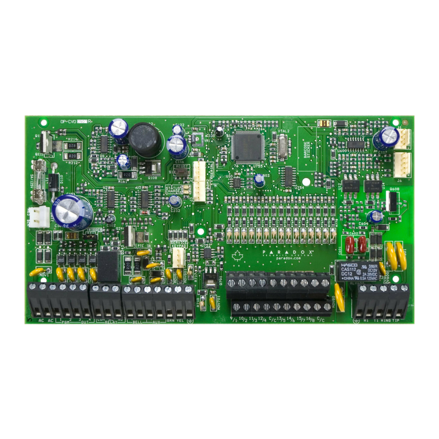
- Page 61 SP4000 PCB Layout port used for voice reporting Paradox Memory Key Status LED: DIALER EBUS with the VDMP3 plug-in voice module. (PMC-4, PMC5) • Flash once every second = Normal • Flashes ON 1 second and OFF 1 port used for GSM reporting...
- Page 62 PGM +/- trigger not supported by the SP5500 EBUS and Dialer used with: VDMP3 plug-in voice module for voice reporting Paradox Memory Key PCS Series GSM communicator module (PMC-4, PMC5) Press and hold the RESET button for five seconds. The STATUS LED will start flashing.
- Page 63 PGMs are grounded (-), or give out 12V (+). EBUS and Dialer used with: VDMP3 plug-in voice module for voice reporting Paradox Memory Key PCS Series GSM communicator module (PMC-4, PMC-5) Press and hold the RESET button for five seconds.
- Page 64 EBUS and Dialer used with: VDMP3 plug-in voice module for voice reporting PCS Series GSM communicator module Paradox Memory Key May be labeled PGM Trigger: This jumper allows you (PMC-4, PMC-5) ADM2 on some to choose whether the solid state...
-
Page 65: Installer Quick Menu
Installer Quick Menu Zones Step Action Details = flash. Programmed zones are lit (button or LED depending on keypad). INSTALLER CODE ] may also be used. MAINTENANCE CODE 2 digits: 01 to 32 ZONE NUMBER Wireless zone = open/close cover or press learn/tamper switch. Hardwired zone = ENROLL OR ERASE ZONE Press [ ]. - Page 66 WinLoad / BabyWare Step Action Details = flash. INSTALLER CODE #] + [ Enter PC phone # (up to 32 digits) and press [ ].* To erase WinLoad / BabyWare PHONE ENTER ENTER phone #, panel ID, and PC password, press the [ ] key for 3 seconds.
- Page 67 PGMs Step Action Details = flash. [ ] may also be used. INSTALLER CODE MAINTENANCE CODE 2 digits: 01 to 16 PGM NUMBER Wireless PGM = Open/close cover. Hardwired PGM = press [ ]. To erase a PGM, ENROLL OR ERASE PGM ENTER press the [ ] key for 3 seconds.
-
Page 68: Index
Index 820 - Fail to comm. clear event timer ........ 23 830 to 840 - Communication timers ........23 841 - VDMP3 max attempts ..........24 Numerics 850 - Test report time of day ..........23 001 to 032 - Zone definitions ..........15 851 to 852 - Report delay .......... - Page 69 IP/GPRS Registration Status ..........28 BabyWare Connecting ..............57 Keypad Instructions ..............57 Quick menu ..............66 Labels (LCD) ............. 47 Through PCS module ..........28 Letters / Special characters ........48 Battery Programming ............. 18 Programming - wireless ..........45 Backup ...............
- Page 70 Wireless keypads ............9 Telephone number Wireless sirens ............. 9 Backup ..............24 Power failure report delay ..........23 Monitoring station ..........24 Programmable output Pager ..............24 Special keys ............24 Options ............... 34 Templates Programming ............. 29 Zone definitions ............15 Test mode ................
- Page 72 Canada and the U.S., call 00-1-450-491-7444, Monday to Friday from 8:00 a.m. to 8:00 p.m. EST. Please feel free to visit our website at www.paradox.com The whole Paradox team wishes you a successful and easy installation. We hope this product performs to your complete satisfaction. Should you have any questions or comments, please visit www.paradox.com.
Need help?
Do you have a question about the Magellan MG5050 and is the answer not in the manual?
Questions and answers