
Related Manuals for Reverse Osmosis RF Series


Summary of Contents for Reverse Osmosis RF Series
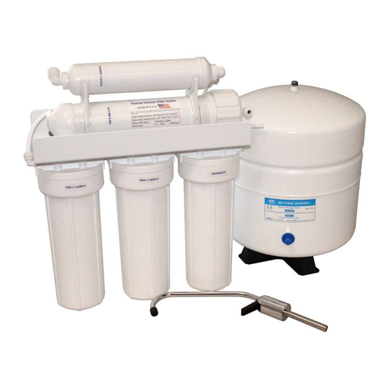
- Page 1 Membrane System User Manual RF – Series 4–Stage, 5–Stage, 5–Stage with Booster Pump 5-STAGE RESIDENTIAL REVERSE OSMOSIS SYSTEM PICTURED...
- Page 2 This page intentionally left blank RF – Series User Manual MKTF – 167-C 05/17...
-
Page 3: Table Of Contents
FAUCET INSTALLATION ......................9 INSTALLATION AND FEEDWATER ADAPTER ..............11 INSTALLATION OF DRAIN SADLE ..................13 POSITIONING THE TANK ...................... 13 REVERSE OSMOSIS UNIT PLACEMENT AND MOUNTING ..........13 TUBING CONNECTIONS ....................... 14 SYSTEM START–UP......................14 FLUSHING THE REVERSE OSMOSIS SYSTEM ..............15 TROUBLESHOOTING ...................... -
Page 4: Tools And Materials For Installation
NOTE: The life of the filters and membrane depend on the quality of water supplied to the reverse osmosis system. PRE–INSTALLATION INSPECTION: After opening the shipping container, locate the following items: 1. Reverse osmosis system 2. Membrane and flow restrictor 3. Storage tank 4. Faucet with mounting hardware 5. -
Page 5: Operation Parameters
Maximum 80 PSI Minimum 40 PSI This reverse osmosis system is designed to operate at a water pressure in the range of 40 to 80 PSI. At pressures lower than this, the quantity as well as quality will be reduced. At higher pressure, severe damage to the system may result. -
Page 6: Membrane And Flow Restrictor Assembly Process
MEMBRANE AND FLOW RESTRICTOR ASSEMBLY PROCESS: 1) Identify membrane element and flow restrictor (color and type depends on membrane being used) included in box: 2) Identify membrane vessel feed cap: 3) Remove feed cap as shown (turn counter clockwise): 4) Insert membrane in direction as shown: RF –... - Page 7 5) Push membrane in as shown: 6) Place feed cap back on as shown (turn clockwise until hand tight): 7) Connect tube to cap as shown: 8) Identify black concentrate (drain) tube: RF – Series User Manual MKTF – 167-C 05/17...
- Page 8 9) Disconnect black tube by following instructions below: 10) Insert flow restrictor in tube: 11) Push in flow restrictor until flush with tube end as shown: Reinsert black tube as shown: RF – Series User Manual MKTF – 167-C 05/17...
-
Page 9: Preparing For Installation
The reverse osmosis system may be mounted that your local distributor be consulted to the side of the sink cabinet or set on the for techniques and other assistance. - Page 10 area to prevent immediate dulling of drill bit. Remove everything from under the sink. Place newspaper or paper towels directly Take the faucet spigot and insert it into the under drilling location in order to catch the faucet base in the hole next to the faucet drill shavings.
-
Page 11: Installation And Feedwater Adapter
Refer to Diagram E for help with this type of valve. Secure an adjustable wrench to the fitting on the cold water side of the sink faucet – NOT THE REVERSE OSMOSIS RF – Series User Manual MKTF – 167-C... - Page 12 NOTE: If hole in copper tube (cold water line) is not adequately pierced, this may prevent sufficient cold water supply to the system and reduce the performance of reverse osmosis Insert black washer into bottom of processing. In this event, open and close the the feed water connector self–piercing valve several times.
-
Page 13: Installation Of Drain Sadle
Mount the drain saddle. Align the drain saddle port with the 1/4” drilled hole using a Reverse Osmosis Unit Placement small drill bit or other small straight object. and Mounting GENTLY TIGHTEN the two screws evenly on both sides of the clamp until the clamp is snug on the pipe. -
Page 14: Tubing Connections
IMPORTANT!! Be very careful not to kink any insert the 1/4” nylon insert into the end of the of the tubing on the reverse osmosis system. tubing. Then insert the tubing into the nylon If tubing is kinked, the tubing can rupture and fitting on the feedwater adapter. -
Page 15: Flushing The Reverse Osmosis System
Flushing the Reverse Osmosis System Lift the reverse osmosis faucet handle until it locks in the upright position. Let the water drip for two hours. After 2 hours, turn off the reverse osmosis faucet. -
Page 16: Troubleshooting
Incoming water pressure must be above 40 PSI. Install a booster pump or Low incoming water pressure. permeate pump. Make sure incoming water pressure is within operating limits. Make sure drain Reverse osmosis membrane is line is not clogged. (See High TDS) Correct cause of fouling and replace fouled. reverse osmosis membrane. - Page 17 Check that the reverse osmosis membrane is correctly installed. correctly sealed in membrane housing. If membrane life is unusually short, find and correct the problem. Reverse osmosis membrane is (Average life is two to three years.) Replace Reverse Osmosis expended. membrane. Product water and drain water lines are Correct plumbing.
-
Page 18: System Drawings
SYSTEM DRAWINGS RF – Series User Manual MKTF – 167-C 05/17... - Page 19 RF – Series User Manual MKTF – 167-C 05/17...
- Page 20 RF – Series User Manual MKTF – 167-C 05/17...
-
Page 21: System Warranty
SYSTEM WARRANTY Year Limited Warranty – Warranty Terms Subject to the terms and conditions set forth hereinafter, manufacturer (hereafter “Manufacturer”) warrants to the original purchaser (hereafter the “Customer”) that the systems and products manufactured by the Manufacturer are free from defects in material and in workmanship for twelve (12) months from the Warranty Commencement Date (as defined below) only when used strictly in accordance with the applicable operating instructions and within the range of the operating conditions specified by the Manufacturer for each such product. - Page 22 Required or replaced products or components shall be returned surface freight. In genuine emergency situations, Manufacturer will at Manufacturer’s sole discretion) forward replacement parts to Customer without waiting for authorized return of the questionable part(s). In such cases, Customer will issue a purchase order or other payment guarantee prior to shipment.
Need help?
Do you have a question about the RF Series and is the answer not in the manual?
Questions and answers