GORMAN-RUPP PUMPS 0 Series Installation, Operation, And Maintenance Manual With Parts List
Hide thumbs
Also See for 0 Series:
Table of Contents
Advertisement
Quick Links
BC
COM-01094-04
May 11, 1981
Rev. A 11‐04‐09
INSTALLATION, OPERATION,
AND MAINTENANCE MANUAL
WITH PARTS LIST
0 SERIES PUMP
MODEL
02C3-X.75 3P , 02C3-X.75 575V 3P
02C3-X1 3P & 02C3-X1 575V 3P
THE GORMAN‐RUPP COMPANY D MANSFIELD, OHIO
www.grpumps.com
D
GORMAN‐RUPP OF CANADA LIMITED
ST. THOMAS, ONTARIO, CANADA
Printed in Canada
e
1981 The Gorman‐Rupp Company
Advertisement
Table of Contents

Related Manuals for GORMAN-RUPP PUMPS 0 Series


Summary of Contents for GORMAN-RUPP PUMPS 0 Series
- Page 1 COM-01094-04 May 11, 1981 Rev. A 11‐04‐09 INSTALLATION, OPERATION, AND MAINTENANCE MANUAL WITH PARTS LIST 0 SERIES PUMP MODEL 02C3-X.75 3P , 02C3-X.75 575V 3P 02C3-X1 3P & 02C3-X1 575V 3P THE GORMAN‐RUPP COMPANY D MANSFIELD, OHIO www.grpumps.com GORMAN‐RUPP OF CANADA LIMITED ST.
- Page 2 Register your new Gorman‐Rupp pump online at www.grpumps.com/register. Valid serial number and e‐mail address required. RECORD YOUR PUMP MODEL AND SERIAL NUMBER Please record your pump model and serial number in the spaces provided below. Your Gorman‐Rupp distributor needs this information when you require parts or service. Pump Model: Serial Number:...
-
Page 3: Table Of Contents
TABLE OF CONTENTS INTRODUCTION ..........PAGE I - 1 SAFETY - SECTION A . - Page 4 TABLE OF CONTENTS (continued) Pump Model ............PAGE E - 3 PUMP AND SEAL DISASSEMBLY AND REASSEMBLY .
-
Page 5: Introduction
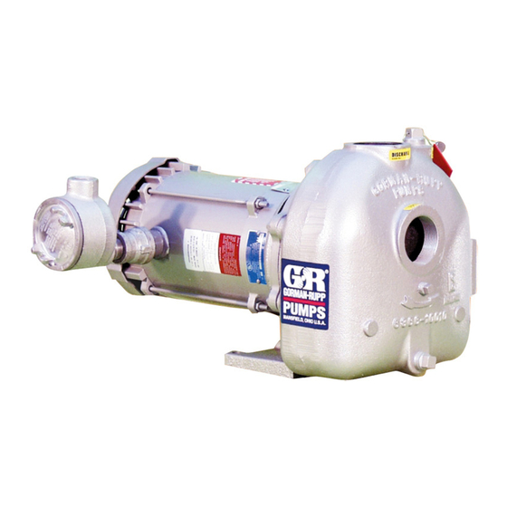
Gorman‐ Rupp pump. This pump is an 0 Series, enclosed impeller, self‐ priming centrifugal model with straight‐in suction, without a suction check valve and close‐coupled to an explosion‐proof electric motor. -
Page 6: Safety - Section A
0 SERIES OM-01094 SAFETY - SECTION A This information applies to 0 Series electric motor driven pumps. Refer to the manual accompanying the motor before attempting to begin operation. This pump is designed to handle petro leum products or other industrial liq... - Page 7 OM-01094 0 SERIES the applicable local code, the National or local code shall take precedence. Overheated pumps can cause severe burns and injuries. If overheating of the pump occurs: Because this pump is designed to han 1. Stop the pump immediately.
-
Page 8: Installation - Section B
0 SERIES OM-01094 INSTALLATION - SECTION B Review all SAFETY information in Section A. specific application. Since the pressure supplied to the pump is critical to performance and safety, Since pump installations are seldom identical, this be sure to limit the incoming pressure to 50% of... -
Page 9: Preinstallation Inspection
OM-01094 0 SERIES PREINSTALLATION INSPECTION The pump assembly was inspected and tested be The electrical power used to operate fore shipment from the factory. Before installation, inspect the pump for damage which may have oc this pump is high enough to cause inju... -
Page 10: Materials
0 SERIES OM-01094 Materials the source of the liquid being pumped; if the line slopes down to the pump at any point along the suction run, air pockets will be created. Either pipe or hose maybe used for suction and discharge lines;... -
Page 11: Suction Line Positioning
OM-01094 0 SERIES If there is a liquid flow from an open pipe into the tance equal to at least 3 times the diameter of the sump, the flow should be kept away from the suc suction pipe. tion inlet because the inflow will carry air down into the sump, and air entering the suction line will re... -
Page 12: Bypass Lines
0 SERIES OM-01094 A check valve in the discharge line is normally rec ELECTRICAL CONNECTIONS ommended, but it is not necessary in low dis charge head applications. This pump is driven by an electric motor. Check that the electrical service available matches the With high discharge heads, it is recommended that motor requirements stamped on the motor name... -
Page 13: Operation - Section C
OM-01094 0 SERIES OPERATION - SECTION C Review all SAFETY information in Section A. Add liquid to the pump casing when: 1. The pump is being put into service for the Follow the instructions on all tags, labels and first time. -
Page 14: Operation
OM-01094 0 SERIES Leakage OPERATION No leakage should be visible at pump mating sur faces, or at pump connections or fittings. Keep all Lines With a Bypass line connections and fittings tight to maintain maxi mum pump efficiency. Since this pump does not have a suction check... -
Page 15: Pump Vacuum Check
OM-01094 0 SERIES equipment. If backflushing is absolutely neces sary, liquid pressure must be limited to 50% of the maximum permissible operating pressure shown on the pump performance curve. Do not operate the pump against a Pump Vacuum Check closed discharge throttling valve for long periods of time. -
Page 16: Troubleshooting - Section D
0 SERIES OM-01094 TROUBLESHOOTING - SECTION D Review all SAFETY information in Section A. Before attempting to open or service the pump: 1. Familiarize yourself with this manual. 2. Disconnect the incoming power to the motor and lock it out to ensure that the pump will remain inopera... - Page 17 OM-01094 0 SERIES TROUBLE POSSIBLE CAUSE PROBABLE REMEDY PUMP STOPS OR Strainer clogged. Check strainer and clean if neces FAILS TO DELIVER sary. RATED FLOW OR Suction intake not submerged at Check installation and correct sub PRESSURE (cont.) proper level or sump too small.
-
Page 18: Preventive Maintenance
0 SERIES OM-01094 equipped) between regularly scheduled inspec PREVENTIVE MAINTENANCE tions can indicate problems that can be corrected Since pump applications are seldom identical, and before system damage or catastrophic failure oc pump wear is directly affected by such things as curs. -
Page 19: Pump Maintenance And Repair - Section E
OM-01094 0 SERIES PUMP MAINTENANCE AND REPAIR - SECTION E MAINTENANCE AND REPAIR OF THE WEARING PARTS OF THE PUMP WILL MAINTAIN PEAK OPERATING PERFORMANCE. STANDARD PERFORMANCE FOR PUMP MODELS 02C3-X.75 ALL VOLTAGES Based on 70_ F (21_ C) clear water at sea level Contact the Gorman‐Rupp Company to verify per... - Page 20 OM-01094 0 SERIES SECTION DRAWING PARTS PAGE Figure 1. Pump Models 02C3-X.75 3P PAGE E - 2 MAINTENANCE & REPAIR...
-
Page 21: Parts List
OM-01094 0 SERIES PARTS LIST Pump Models 02C3-X.75 3P , 02C3-X.75 575V 3P 02C3-X1 3P , 02C3-X1 575V 3P (From S/N 237887 Up) If your pump serial number is followed by an “N”, your pump is NOT a standard production model. Contact the Gorman‐Rupp Company to verify part numbers. -
Page 22: Pump And Seal Disassembly And Reassembly
OM-01094 0 SERIES PUMP AND SEAL DISASSEMBLY 3. Allow the pump to completely cool if overheated. AND REASSEMBLY 4. Check the temperature before opening any covers, plates, or Review all SAFETY information in Section A. plugs. 5. Close the suction and discharge Follow the instructions on all tags, label and decals valves. -
Page 23: Impeller Removal
0 SERIES OM-01094 charge hoses and piping must be re moved from the pump before lifting. Impeller Removal Most cleaning solvents are toxic and flammable. Use them only in a well ven For access to the impeller (2), disengage the tilated area free from excessive heat, screws (5) and remove the vane plate (19). -
Page 24: Impeller Installation
OM-01094 0 SERIES RETAINER SEAL PLATE SPRING IMPELLER STATIONARY ELEMENT IMPELLER SHIMS IMPELLER SHAFT BELLOWS DRIVE BAND SPRING ROTATING RETAINER STATIONARY ELEMENT SEAT Figure 2. Seal Assembly Subassemble the rotating element into the retainer and bellows. Lubricate the I.D. of the bellows with water and slide this subassembly onto the shaft until the polished faces contact. -
Page 25: Pump Reassembly
0 SERIES OM-01094 Step 1 Step 2 Step 3 Figure 3. Centering Impeller Within Vane Plate Scroll Install the correct thickness of impeller shims (17) Pump Reassembly and screw the impeller onto the shaft until fully Install the vane plate O‐ring (21) onto the vane seated. - Page 26 For Warranty Information, Please Visit www.grpumps.com/warranty or call: U.S.: 419-755-1280 Canada: 519-631-2870 International: +1-419-755-1352 GORMAN‐RUPP PUMPS...
Need help?
Do you have a question about the 0 Series and is the answer not in the manual?
Questions and answers