STIEBEL ELTRON DHB-E 11 SLi electronic Operation And Installation
Electronically controlled instantaneous water heater
Hide thumbs
Also See for DHB-E 11 SLi electronic:
- Operating and installation (148 pages) ,
- Operating and installation manual (104 pages) ,
- Operating and installation (116 pages)
Table of Contents
Advertisement
BEDIENUNG UND INSTALLATION
OPERATING AND INSTALLATION
UTILISATION ET INSTALLATION
GEBRUIK EN INSTALLATIE
OBSŁUGA I INSTALACJA
OBSLUHA A INSTALACE
Elektronisch geregelter Durchlauferhitzer | Electronically controlled instantaneous
water heater | Chauffe-eau instantanés à régulation électronique | Elektronisch
geregelde doorstromer | Elektronicznie regulowany przepływowy ogrzewacz wody |
Elektronicky regulovaný průtokový ohřívač
» DHB-E 11 SLi electronic
» DHB-E 13 SLi electronic
» DHB-E 18 SLi 25 A electronic
» DHB-E 18/21/24 SLi electronic
» DHB-E 27 SLi electronic
electronic
°C
45
40
50
35
55
30
60
Advertisement
Table of Contents

Related Manuals for STIEBEL ELTRON DHB-E 11 SLi electronic


Summary of Contents for STIEBEL ELTRON DHB-E 11 SLi electronic
- Page 1 | Chauffe-eau instantanés à régulation électronique | Elektronisch geregelde doorstromer | Elektronicznie regulowany przepływowy ogrzewacz wody | Elektronicky regulovaný průtokový ohřívač » DHB-E 11 SLi electronic » DHB-E 13 SLi electronic » DHB-E 18 SLi 25 A electronic »...
-
Page 2: Table Of Contents
CoNTENTS SPECIAL INFORMATION Troubleshooting �������������������������������������������� 31 Maintenance ������������������������������������������������ 32 OPERATION Specification ������������������������������������������������ 32 General information ��������������������������������������� 20 16.1 Dimensions and connections ��������������������������������� 32 Safety instructions ���������������������������������������������� 20 16.2 Wiring diagram ������������������������������������������������� 32 Other symbols in this documentation ���������������������� 20 16.3 DHW output ������������������������������������������������������... -
Page 3: Special Information
SPECIAL INforMATIoN SPECIAL INforMATIoN | oPErATIoN General information General information SPECIAL INforMATIoN oPErATIoN - The appliance may be used by children aged 3 General information and older and persons with reduced physical, sensory or mental capabilities or a lack of ex- The chapters “Special Information”... -
Page 4: Units Of Measurement ����������������������������������������� 21 16.3 Dhw Output
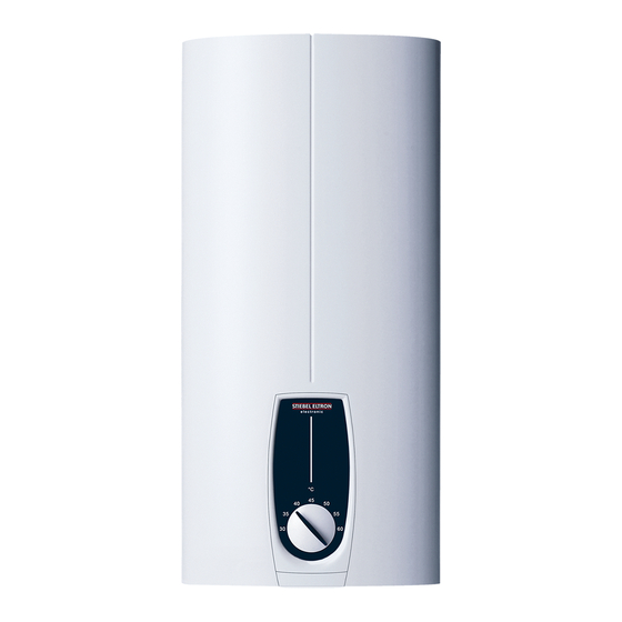
oPErATIoN Safety Test symbols Symbol Meaning Material losses See type plate on the appliance. (appliance damage, consequential losses and environmen- tal pollution) Appliance disposal Appliance description The electronically controlled instantaneous water heater main- tains a constant outlet temperature up to its output limit, irre- f This symbol indicates that you have to do something. -
Page 5: Recommended Settings
oPErATIoN Cleaning, care and maintenance Recommended settings Thermostatic valve If the appliance is being operated with a thermostatic valve, we DHB-E ... SL recommend setting the temperature on the appliance to maxi- mum. The required temperature can then be set at the thermo- static valve. -
Page 6: Installation
INSTALLATIoN Safety INSTALLATIoN Accessories Taps/valves - MEKD mono lever kitchen pressure tap Safety - MEBD mono lever bath pressure tap Only a qualified contractor should carry out installation, commis- Plug G ½ A sioning, maintenance and repair of the appliance. If you use pressure taps for finished walls other than those rec- ommended in the accessories, please use the plugs. -
Page 7: Preparations
INSTALLATIoN Preparations Preparations Water installation - No safety valve is required. Installation site f Flush the water line thoroughly. Taps/valves Material losses Install the appliance in a room free from the risk of frost. Use suitable pressure taps/valves (see chapter “Installation / Appliance description / Accessories”). -
Page 8: Appliance With Adjustable Connected Load
INSTALLATIoN Installation Appliance with adjustable connected load 10.1 Standard installation The appliance DHB-E 18/21/24 SL is set to 21 kW when delivered. Opening the appliance If the appliance is to be installed with a different output, take the following steps: f Plug in the coding card according to the selected output; for selectable output and fuse protection of the appliance, see chapter “Installation / Specification / Data table”. - Page 9 INSTALLATIoN Installation Making the water connection Installing the appliance Material losses Carry out all water connection and installation work in accordance with regulations. f Seal and insert the twin connectors. 5 Nm f For easier installation, push the cable grommet of the upper electrical connection into the back panel from behind.
-
Page 10: Completing The Installation
INSTALLATIoN Commissioning 11. Commissioning Making the electrical connection WARNING Electrocution WARNING Electrocution Carry out all electrical connection and installation work Commissioning may only be carried out by a qualified in accordance with relevant regulations. contractor in accordance with safety regulations. WARNING Electrocution The connection to the power supply must be in the form 11.1 Initial start-up... -
Page 11: Recommissioning
INSTALLATIoN Shutdown 11.2 Recommissioning 13.2 Electrical connection on finished walls Material losses Note To ensure that the bare wire heating system is not dam- This type of connection changes the protection rating of aged following an interruption to the water supply, the the appliance. -
Page 12: Connecting A Load Shedding Relay
INSTALLATIoN Installation options 13.4 Connecting a load shedding relay Note When operating additional electric appliances, such as electric Observe the tap manufacturer's instructions. storage heaters, install a load shedding relay in the distribution board. The relay responds when the instantaneous water heater 13.7 Water installation on finished walls;... -
Page 13: Wall Mounting Bracket When Replacing An Appliance
INSTALLATIoN Installation options 13.11 Pivoting appliance cover The appliance cover can be turned round for undersink instal- lation. 1 Base part of the back panel 2 Connection pieces delivered in the pack 3 Screw 13.9 Wall mounting bracket when replacing an appliance An existing STIEBEL ELTRON wall mounting bracket may be used when replacing appliances (except for DHF instantaneous water... - Page 14 INSTALLATIoN Troubleshooting 14. Troubleshooting WARNING Electrocution To test the appliance, it must be supplied with power. Indication variants for diagnostic traffic light (LED) Illuminates in the event of a fault Yellow Illuminates during heating operation Green Flashing: Appliance is supplied with mains power fault / LED diagnostic traffic light signal Cause remedy The appliance does not start.
-
Page 15: Wiring Diagram
INSTALLATIoN Maintenance 15. Maintenance Alternative connection options WARNING Electrocution Before any work on the appliance, ensure omnipolar disconnection from the power supply. Draining the appliance The appliance can be drained for maintenance work. WARNING Burns Hot water may escape when you drain the appliance. f Close the 3-way shut-off valve or the shut-off valve in the cold water supply line. -
Page 16: Pressure Drop
DHB-E 13 SLi DHB-E 18 SLi 25 A DHB-E 18/21/24 SLi DHB-E 27 SLi 232013 232014 232015 232016 232017 Manufacturer STIEBEL ELTRON STIEBEL ELTRON STIEBEL ELTRON STIEBEL ELTRON STIEBEL ELTRON Load profile Energy efficiency class Annual power consumption Energy conversion efficiency Default temperature setting °C... -
Page 17: Data Table
INSTALLATIoN INSTALLATIoN | GUArANTEE | ENVIroNMENT AND rECYCLING Specification Specification 16.7 Data table DHB-E 11 SLi DHB-E 13 SLi DHB-E 18 SLi 25 A DHB-E 18/21/24 SLi DHB-E 27 SLi 232013 232014 232015 232016 232017 Electrical data Rated voltage Rated output 10.1 11 12.2 13.5 14.5 16.2... - Page 18 Deutschland Verkauf Tel. 05531 702-110 | Fax 05531 702-95108 | info-center@stiebel-eltron.de STIEBEL ELTRON GmbH & Co. KG Kundendienst Tel. 05531 702-111 | Fax 05531 702-95890 | kundendienst@stiebel-eltron.de Dr.-Stiebel-Straße 33 | 37603 Holzminden Ersatzteilverkauf Tel. 05531 702-120 | Fax 05531 702-95335 | ersatzteile@stiebel-eltron.de Tel.
Need help?
Do you have a question about the DHB-E 11 SLi electronic and is the answer not in the manual?
Questions and answers