Table of Contents
Advertisement
Quick Links
4-20mA Current Splitter
Phone: +1 561 779 5660 E-mail : Info@datexel.com - Web Site www.datexel.com
FEATURES
- Universal configurable input for:
mV, Tc, RTD, Res, Potentiometer, V and mA
- Two outputs configurable in current or voltage
- Trip alarm
- Configurable by dip-switch or PC
- High accuracy
- On-field reconfigurable
- Galvanic isolation among all the ways
- UL / CE mark
- Suitable for DIN rail mounting in compliance
with EN-50022 and EN-50035
GENERAL DESCRIPTION
The universal isolated converter DAT 4530 is able to measure and linearise voltage, current and resistance signals, potentiometers and the standard
thermocouples and RTDs with, if required, the cold junction compensation, the wires compensation. For mV, V and mA input it is possible to set an
option for the fast sampling (option HS) or to extract the square root of the measured signal (option SQRT). In function of programming, the measured
values are converted in a current or voltage signal on the two outputs. Moreover an output contact is available as trip alarm.
By dip-switches accessible opening the window on the side of the enclosure, it is possible to select the input type and range and the output type without
recalibrate the device.
By Personal Computer the user can set the two outputs with independent settings, the parameters of the Trip Alarm and the optional parameters for his
own necessity;
The galvanic isolation between input, outputs and power supply eliminates the effects of all ground loops eventually existing and allows the use of the
converter in heavy environmental conditions found in industrial applications. The device guarantees high accuracy and performances stability both
versus time and temperature.
The DAT 4530 is in compliance with the Directive UL 61010-1 for US market and with the Directive
It is housed in a plastic enclosure of 12.5 mm thickness suitable for DIN rail mounting in compliance with EN-50022 and EN-50035 standards.
USER INSTRUCTIONS
The connections must be made as shown in the section "Connections".It is possible to configure the converter on field by dip-switch or Personal
Computer as shown in the section " Programming ". The configuration by dip-switches can be made also if the device is powered (note: after the
configuration the device takes some seconds to provide the right output measure ).
INPUT
Input type
Min
TC (
.)
CJC int./ext
J
-200°C
K
-200°C
S
0°C
R
0°C
B
0°C
E
-200°C
T
-200°C
N
-200°C
Voltage
mV
-100 mV +90 mV
mV
-100 mV +200 mV
mV
-100 mV +800 mV
RTD (
2, 3, 4 wires)
Pt100
-200°C
Pt1000
-85°C
Ni100
-60°C
Ni1000
-60°C
0 W
RES.
(2, 3, 4 wires)
0 W
0 %
Pot.
(Rnom.< 50KW)
Voltage
-10 V
Current
0 mA
Accuracy
(1)
mV, TC
the higher of ±0.1% and ±12 uV
RTD
the higher of ±0.1% and ±0.2°C
Res.
the higher of ±0.1% and ±0.15
Potentiometer
± 0.05 % f.s.
Voltage
the higher of ±0.1% and ± 2 mV
mA
the higher of ±0.1% and ± 6 uA
mV, V, mA
± 0.5 % f.s (opt. HS)
Linearity
(1)
TC, RTD
± 0.1 % f.s.
mV, V, mA
± 0.05 % f.s.
(1) referred to the input Span (difference between max. and min.)
TECHNICAL SPECIFICATIONS (Typical @ 25 °C and in nominal conditions)
Input impedance
TC, mV
Max
Span min
mA
RTD excitation current
1200°C
100°C
RTD, Res
1300°C
100°C
Aux. Voltage
1750°C
400°C
Line resistance influence
1750°C
400°C
TC, mV
1850°C
400°C
RTD 3w
1000°C
100°C
RTD 4w
400°C
100°C
1300°C
100°C
Thermal drift
Full scale
5 mV
CJC
10 mV
CJC Comp.
20 mV
OUTPUT (2 CHANNELS)
850°C
50°C
Output type
185°C
30°C
Current
180°C
50°C
Voltage
150°C
30°C
500 W
50 W
Output resolution
Current
2000 W
50 W
Voltage
100 %
10 %
Aux. Voltage
10 V
1 V
Burn-out values
Max. output value
20 mA
1 mA
Min. output value
Output load Resistance - Rload
Current output
Voltage output
Short circuit current
Response time
ALARM TRIP (SSR)
Contact
Max Load (resistive) :
Voltage
Current
mV
Tc
RTD/RES
Pot
V
mA
>= 10 MW
~22 W
400 uA
>18V @ 20mA
(1)
<=0.8 uV/Ohm
(50W max balanced)
0.05%/W
0.005%/W
(100W max balanced)
(1)
± 0.01% / °C
± 0.01% / °C
± 0.5°C
Min
Max
0 mA
20 mA
0 V
10 V
7 uA
4 mV
>12V @ 20mA
22 mA or 11 V
0 mA or -0.6 V
< 500 W
> 10 KW
30 mA max.
400 ms
(10÷ 90%)
about
100 ms (option HS)
SPST
48 Vdc / 30 Vac
0.4 A
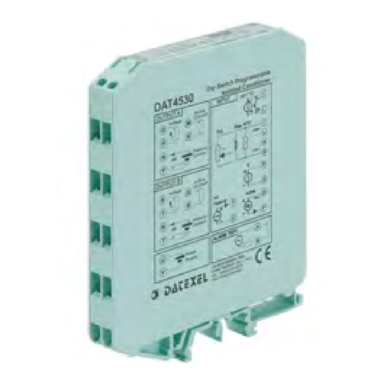
Universal isolated converter
configurable by Dip-Switch or PC
double output & trip amplifier
DAT 4530
DAT 4530
V
mA
V
mA
Alarm
DC SUPPLY
+
-
CSA C22.2 No 61010-1 for the
POWER SUPPLY
Power supply voltage
Reverse polarity protection
Current consumption
Current output
Voltage output
ISOLATION
Among all the ways
ENVIRONMENTAL CONDITIONS
Operative Temperature
UL Operative Temperature
Storage Temperature
Humidity (not condensed)
Maximum Altitude
Installation
Min Span
Category of installation
4 mA
Pollution Degree
1 V
MECHANICAL SPECIFICATIONS
Material
IP Code
Wiring
Tightening Torque
Mounting
Weight
CERTIFICATIONS
EMC ( for industrial environments)
Immunity
Emission
UL
US Standard
Canadian Standard
CCN
Typology
Classification
File Number
Canadian market.
20 .. 30 Vdc
60 Vdc max
90 mA max.
30 mA max.
1500 Vac,
50 Hz, 1 min
-20°C .. +60°C
-10°C .. +60°C
-40°C.. +85°C
0 .. 90 %
2000 m
Indoor
II
2
Self-extinguish plastic
IP20
wires with diameter
0.8÷2.1 mm
2
/AWG 14-18
0.8 N m
in compliance with DIN
rail standard EN-50022
and EN-50035
about 90 g.
EN 61000-6-2
EN 61000-6-4
UL 61010-1
CSA C22.2 No 61010-1
NRAQ/NRAQ7
Open Type device
Industrial Control
Equipment
E352854
Advertisement
Table of Contents

Related Manuals for Datexel DAT 4530

Summary of Contents for Datexel DAT 4530
- Page 1 GENERAL DESCRIPTION The universal isolated converter DAT 4530 is able to measure and linearise voltage, current and resistance signals, potentiometers and the standard thermocouples and RTDs with, if required, the cold junction compensation, the wires compensation. For mV, V and mA input it is possible to set an option for the fast sampling (option HS) or to extract the square root of the measured signal (option SQRT).
- Page 2 THRESHOLD OPERATION LOW ALARM THRESHOLD HIGH ALARM THRESHOLD Trip level + hyst. Trip level Trip level - hyst. Trip level T(delay) T(delay) T(delay) T(delay) Active relay Active relay For the low alarm the relay goes on when the input signal is lower than the For the high alarm the relay goes on when the input signal is higher than the trip level and after the delay time.
- Page 3 DIP-SWITCH CONFIGURATION TABLES TAB.1 – Input type settings NOTES: EPROM * Tc J Res. 2KW * To set the input range refer to the TAB.4 (next pages) referred to the input type selected by the TAB.1. 90 mV Tc K Res.
- Page 4 TAB.4c – Resistance < 2 Kohm input scale settings. Zero Full Scale Default Default 1150 1600 1175 1650 1200 1700 1225 1750 1250 1800 1275 1850 1300 1900 1325 1950 1350 2000 1375 2000 1000 1400 2000 1025 1425 2000 1050 1450 2000...
- Page 5 TAB.4f – Current input scale settings Zero Full Scale Default Default 11.5 11.75 16.5 12.25 17.5 12.5 12.75 18.5 13.25 19.5 13.5 13.75 10.25 14.25 10.5 14.5 10.75 14.75 11.25 15.5 TAB.4g – Voltage input scale settings Zero Full Scale Volt Volt Volt...
-
Page 6: Installation Instructions
DESCRIPTION STATE ORDER CODE EXAMPLE: Device powered GREEN DAT 4530 / Pt100 / 0 ÷ 200 °C / 4 ÷ 20 mA / 4 ÷ 20 mA / 3wires Device not powered Input type BLINKING Wrong dip-switches settings Input scale...
Need help?
Do you have a question about the DAT 4530 and is the answer not in the manual?
Questions and answers