Table of Contents

Subscribe to Our Youtube Channel
Related Manuals for GUIDANCE MARINE 20- Series


Summary of Contents for GUIDANCE MARINE 20- Series
- Page 1 CyScan AS Installer’s Guide featuring CyScan AS reflector detection Guidance Marine Ltd, 5 Tiber Way, Meridian Business Park, Leicester, LE19 1QP, UK www.guidance.eu.com T: +44116 229 2600 E: sales@guidance.eu.com www.marine.direct...
- Page 2 No 50 26 Jul 2001 100.00 mm Copyright © Guidance Marine Limited. All Rights Reserved. Copyright in the whole and every part of this document belongs to Guidance Marine Limited (the “Owner”) and may not be used, sold, transferred, copied or reproduced in LASER 50.00mm...
-
Page 3: Table Of Contents
Table of Contents Introduction ......................5 Installing the Control PC ................26 Welcome �����������������������������������������������������������������������������������������������������������������������6 Installing CyScan Client Software onto a Computer ��������������������������������������������������27 System Overview ����������������������������������������������������������������������������������������������������������7 Configuring the CyScan System .............. 28 What is Absolute Signature (AS)�����������������������������������������������������������������������������������8 Using the CyScan Service Interface ���������������������������������������������������������������������������29 CyScan Sensor Part Names �����������������������������������������������������������������������������������������9 Network Communication Settings �����������������������������������������������������������������������������30 Serial Numbers &... - Page 4 Table of Contents (continued) Index ���������������������������������������������������������������������������������������������������������������������������59 Document History ������������������������������������������������������������������������������������������������������61...
-
Page 5: Introduction
Introduction This section provides an introduction and overview of the CyScan system. It contains the following sections: • Welcome (page 6) • System Overview (page 7) • What is Absolute Signature (AS) (page 8) • CyScan Sensor Part Names (page 9) •... -
Page 6: Welcome
Welcome Note: Installation of a CyScan system should be carried Welcome to the CyScan AS Installer’s Guide. It explains how to commission and install the out by a suitably qualified and competent engineer. CyScan system onto a vessel and how to install the CyScan Service Interface (CSI) and Dashboard. -
Page 7: System Overview
System Overview CyScan is a high accuracy relative position reference sensor. It provides positional CyScan Client Software information to a vessel’s DP system, allowing it to keep station relative to a target structure The CyScan Service Interface (CSI) and CyScan Dashboard are software applications or another vessel. -
Page 8: What Is Absolute Signature
What is Absolute Signature (AS)? It is well known that laser Position Reference Sensors (PRS) cannot always distinguish How does AS work? between different types of reflector targets. Standard laser PRS, such as CyScan Mk4, The AS prism has a black tinted lens filter which gives it a unique signature that the CyScan will detect and track prisms and tube targets as well as all other reflective objects (known AS sensor can exclusively identify as the AS prism target. -
Page 9: Cyscan Sensor Part Names
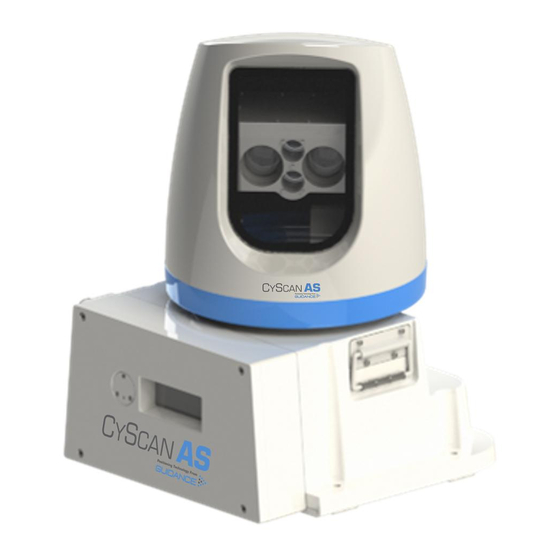
CyScan Sensor Part Names The diagram below shows the key parts of the sensor unit and the various names that are used throughout this guide: Rotor Window Rotor Access Cover Sensor Information Power Display DP Feed Cable Gland Plate Client Data Base Plate... - Page 10 CyScan Sensor Part Names (Continued) Power DP Feed 2 DP Feed 1 Client Data Alternative model with 4 cable glands.
-
Page 11: Serial Numbers & Software Versions
Serial Numbers & Software Versions Serial numbers and Software Version Numbers are used to identify the hardware configuration and product revision of each CyScan unit. They will be requested by Guidance Marine in the event of an application service support call to the company. -
Page 12: Installing The Sensor Hardware
Installing the Sensor Hardware This section contains the following pages: • Where to Mount the Sensor (page 13) • Sensor Dimensions and Mounting Template (page 14) -
Page 13: Where To Mount The Sensor
Where to Mount the Sensor Sensor Mounting Locations The CyScan system is designed for permanent or semi-permanent installation on-board a vessel. Often, a custom-fabricated plinth is used to provide the optimum height and location for mounting the CyScan sensor. On all types of vessel the sensor should be mounted: •... -
Page 14: Sensor Dimensions And Mounting Template ��������������������������������������������������������������14 Additional Information
Sensor Dimensions and Mounting Template Sensor Clearance Mounting Template The exact dimensions of the CyScan AS unit’s footprint are shown below. Mount the baseplate horizontally. Additional information shown on the right could be beneficial when mounting the CyScan unit. Please refer to Document No: 94-0062-4 CyScan Mounting Template to view the information in larger format. -
Page 15: Installing The Cables
Installing the Cables This section contains the following pages: • Cable Specifications (page 16) • UPS Specifications (page 17) • Legacy CyScan Sensor Connections (page 18) • Legacy Client and DP Feed Connections - Ethernet Client, Serial DP (page 19) •... -
Page 16: Cable Specifications
Operate between -40°C to +80°C. Note: Data cables should not be run across or next to power cables to avoid signal interference problems. Cable Description Guidance Marine Part Numbers (40m lengths) Serial Signal Wiring to DP System 33-0122-3 Minimum 5-core shielded data cable. -
Page 17: Ups Specifications
UPS Specifications The power supply to the CyScan sensor and the computer(s) running the CyScan Service Interface and Dashboard must come directly from a Un-interruptible Power Supply (UPS), which will also act as the power disconnection point. The CyScan system comprises the following components, the UPS system used must meet these minimum specifications: CyScan AS Sensor Type 3 Marine Processor Power Adaptor... -
Page 18: Legacy Cyscan Sensor Connections �������������������������������������������������������������������������18 Nmea0183P Format
Legacy CyScan Sensor Connections To Connect a Cable to the CyScan Sensor Power terminals on Cable ties connector board 1. Remove the 4 screws from the access cover and remove the plate from the sensor unit CyScan Sensor Part Names to expose the connector board. -
Page 19: Legacy Client And Dp Feed Connections - Ethernet Client, Serial
Legacy Client and DP Feed Connections - Ethernet Client, Serial DP For an Ethernet configuration sensor, connect the Ethernet cable to Ethernet 0 and the DP serial cable to Serial 1: Connect Ethernet Port 0 to the Marine Processor and Serial Port 1 to the DP system. Configure the serial connections as shown below: To Connect Cables to RS422 Link... -
Page 20: Legacy Client And Dp Feed Connections - Ethernet Client, Dual Serial
Legacy Client and DP Feed Connections - Ethernet Client, Dual Serial DP For an Ethernet configuration sensor, connect the Ethernet cable to Marine Processor and Two DP serial cables to Serial 1 & Serial 2: Connect Ethernet Port 0 to the Marine Processor, Serial Port 0 to DP System 1 and Serial Port 1 to DP system 2. Configure the serial connections as shown below: To Connect Cables to RS422 Link... -
Page 21: Legacy Client And Dp Feed Connections - Serial Client, Serial
Legacy Client and DP Feed Connections - Serial Client, Serial DP Serial 1 For a Serial configuration sensor, connect the Serial to the Marine Processor and Serial to the DP Feed: RS422 Link 1 RX- 9600 baud 2 RX+ Connect Serial Port 0 to the Marine Processor and Serial Port 1 to the DP system. 8 bits 3 TX- Configure the serial connections as shown below:... -
Page 22: Cyscan As Sensor Connections
CyScan AS Sensor Connections To Connect a Cable to the CyScan Sensor Power terminals on Cable ties connector board 1. Remove the 4 screws from the access cover and remove the plate from the sensor unit CyScan Sensor Part Names to expose the connector board. -
Page 23: Cyscan As Client And Dp Feed Connections - Ethernet Client, Serial
CyScan AS Client and DP Feed Connections - Ethernet Client, Serial DP For an Ethernet configuration sensor, connect the Ethernet cable to Ethernet 0 and the DP serial cable to Serial 1: Connect Ethernet Port 0 to the Marine Processor and Serial Port 1 to the DP system. Configure the serial connections as shown below: To Connect Cables to Power/Serial Plugs:... -
Page 24: Cyscan As Client And Dp Feed Connections - Ethernet Client, Dual Serial
CyScan AS Client and DP Feed Connections - Ethernet Client, Dual Serial DP For an Ethernet configuration sensor, connect the Ethernet cable to Marine Processor and Two DP serial cables to Serial 1 & Serial 2: Connect Ethernet Port 0 to the Marine Processor, Serial Port 1 to DP System 1 and Serial Port 0 to DP system 2. Configure the serial connections as shown below: To Connect Cables to Power/Serial Plugs:... -
Page 25: Cyscan As Client And Dp Feed Connections - Serial Client, Serial
CyScan AS Client and DP Feed Connections - Serial Client, Serial DP Serial 1 For a Serial configuration sensor, connect the Serial to the Marine Processor and Serial to the DP Feed: 1 GND Connect Serial Port 0 to the Marine Processor and Serial Port 1 to the DP system. 2 RX+ RS422 Link 3 RX-... -
Page 26: Installing The Control Pc
Installing the Control PC Before setting up the CyScan client computer(s), refer to the relevant installation sheet(s) for dimensions and connections information: For a Type 3 Marine Processor: • 94-0465-4 Type 3 Marine Processor and Display Installation Sheet For a Hatteland Panel PC: •... -
Page 27: Installing Cyscan Client Software Onto A Computer
This section explains how to install the CyScan client software onto computers running Windows 7 or later. If this Marine Processor has been supplied by Guidance Marine, it will have been shipped with the client software already installed. If the client PC has not been supplied by Guidance Marine, then the Guidance Prerequisites should be installed before installing any client software. -
Page 28: Configuring The Cyscan System
Configuring the CyScan System This section contains the following pages: • Using the CyScan Service Interface (page 29) • Network Communication Settings (page 30) • Vessel Calibration (page 32) • Static Blanking Zones (page 35) • DP Feed Configuration (page 36) •... -
Page 29: Using The Cyscan Service Interface
(Alternatively, run from the Start menu: Connected State - Whether the CyScan Service Interface is “Connected” to the sensor or Start > All Programs > Guidance Marine Ltd > CyScan > CyScan Service Interface). “Disconnected”. Sensor State - “Running” or “Suspended” when the CyScan Service Interface is connected;... -
Page 30: Network Communication Settings
Network Communication Settings To Modify the Sensor’s Communications Settings The Network Config tab of the CyScan Service Interface is used to view and amend the CyScan Service Interface’s definition of its communications link with the sensor, and to Option 1 reconfigure the sensor’s own communications settings (e.g. - Page 31 10. Leaving at least 30 seconds after step 7, click on the Connect button. Option 2 1. Contact Guidance Marine and obtain a new sensor network configuration file (connect.ini). 2. Click on the Take Command button if the CyScan Service Interface is not already In Command mode.
-
Page 32: Vessel Parameters
Vessel Parameters The Vessel tab allows you to define the dimensions of the vessel outline on the BEV, the name of the vessel and other items as follows: • Vessel Name: The name of your ship (displayed on the Dashboard). •... - Page 33 Vessel Parameters (Continued) Sensor Facing Forward Bearing Offset Connection panel facing aft, Sensor parallel with vessel Enter the correct Bearing Offset value on the Vessel tab Vessel Parameters (See on page 32). centre-line. Bearing Offset = 180° • If the sensor is facing directly Aft, enter a 0°...
- Page 34 Vessel Parameters (Continued) Bow and Starboard Offsets Reset, Import and Export of Vessel Calibration The Bow Offset is the distance from the sensor to the vessel’s bow. The Vessel Calibration can be reset to factory defaults, imported from an XML or exported to The Starboard Offset is the distance from the sensor to the starboard edge of the vessel.
-
Page 35: Static Blanking Zones
Static Blanking Zones Blanking Zones are used to mask segments of the scan rotation that are obscured by the vessel’s superstructure. While the scanner passes through a blanking zone, the laser is switched off to prevent unwanted reflections from interfering with the target data. Two types of blanking zone can be configured on a CyScan system: •... -
Page 36: Dp Feed Configuration
DP Feed Configuration The CyScan system provides positional data messages to your vessel’s DP (Dynamic Positioning) system and the format and behaviour of this output stream needs to meet the requirements of the DP system. The current DP configuration settings are displayed on the DP Config tab of the CyScan DP Message Types Service Interface, along with the most recent message emitted. - Page 37 DP Feed Configuration (Continued) DP Feed Behaviour The following behaviour applies when no target tracking is in progress: The DP Feed Behaviour options are two tick-boxes on the DP Config tab of the CyScan For a DP Feed format that does not contain status flags: Service Interface:: Keep Feed Allow Zero...
-
Page 38: System Parameters
System Parameters When the CyScan Service Interface is in command mode, the Parameters tab displays a large number of settings and variables which define how the system behaves and describe its current state. They are arranged in groups (General, Sensor, Power Control, etc) and some of the parameters can be edited from the CyScan Service Interface. - Page 39 System Parameters (Continued) To Edit System Parameters Alarms Tab: The System Parameters can be reset to factory defaults, imported from an XML file or exported The Alarm tab display a list of alarms that have been raised by the sensor. Active alarms will to an XML file.
- Page 40 Additional Information This section contains the following pages: • Target Types (page 41) • Positioning and Mounting Targets (page 42) • DP Message Types (page 43) • CyScan AS Installation Checklist (page 48) • Cable Routing Diagrams (page 49) • Sensor Information Display - Error Messages (page 54) •...
-
Page 41: Target Types
Target Types CyScan can operate successfully with flat, cylindrical or prism targets. Targets can be bought online from www.marine.direct. Cylindrical Targets Prism Targets Absolute Signature Prism Cylindrical targets can be used up to Prism clusters with multiple 6cm elements AS Prism with multiple 6cm elements for approximately 300 metres. -
Page 42: Positioning And Mounting Targets
Positioning and Mounting Targets Target Installation Key to the operation of the CyScan system is the correct installation of targets. Please follow the guidelines given below when installing targets on the structure/vessel. Once the targets are installed, their relative positions can be automatically surveyed by the system. -
Page 43: Dp Message Types
A - available; V - void • • HHHH status word in hexadecimal. Up to 16 bits defined by Guidance Marine in a HHHH status word in hexadecimal. Up to 16 bits defined by Guidance Marine in a separate specifications document separate specifications document. -
Page 44: Ascii17 Format
DP Message Types (Continued) † Nautronix Standard ASCII17 Format A 17 character string delimited only by <CR> and <LF> with bearing measured bow clockwise. A 14 character string delimited only by <CR> and <LF> with bearing measured bow clockwise. Character Index Description Format Character Index... -
Page 45: Mt Custom Dp String
DP Message Types (Continued) MT Custom DP String The MT Custom DP String adopts NMEA0183 conventions with a minimum length of 63 and maximum length of 80 characters. When multi-target tracking, multiple messages are emitted per rotor revolution: one for each target in the tracking group. $PGNMT,T,HH˽MM˽SS.SSS,[NNNN]N,E,[IIII]I,S,[RRR]R.RR,Z ,[BB]B.BB,Z ,[Q]Q,[AAA]A,XXXX*CC<CR><LF>... -
Page 46: Rolls-Royce Custom Dp String
DP Message Types (Continued) Rolls-Royce Custom DP String The Rolls-Royce Custom DP String adopts NMEA0183 conventions with a minimum length of of 82 characters. When multi-target tracking, multiple messages are emitted per rotor revolution: one for each target in the tracking group. $PGNRR,T,YYYY MM DD,HH MM SS.SSS,…N,…I,S,…R.RR,Z ,…B.BB,Z ,…Q,±…r.r,±…p.p,…A,XXXX*CC<CR><LF>... -
Page 47: Kongsberg (Custom)
DP Message Types (Continued) Kongsberg (Custom) The Kongsberg Custom DP string adopts NMEA0183 conventions and has a length of 40 characters. When multi-target tracking, multiple messages are emitted per rotor revolution: one for each target in the tracking group. $PGNKM,II,RRRR.R,Z ,BBB.B,Z ,HHHH*CC<LF><CR>... -
Page 48: Cyscan As Installation Checklist
CyScan AS Installation Checklist Vessel name: ................CyScan unit s/n: ..................Computer s/n: ............Check Requirement Checked Notes/record setting Check Requirement Checked Notes/record setting (Initial) (Initial) Mechanical Sensor Details / Vessel Calibration Sensor Line of sight to expected target positions DP string as required by DP supplier Supplier: Required space around the sensor... -
Page 49: Cable Routing Diagrams
CyScan Sensor to the Type 3 Marine DP System UPS Processor should not exceed 90 metres Emergency Breaker Box Ethernet in length. Please contact Guidance Marine if longer Ethernet Cable P/N 33-0124-3 (40m) distances are required. DP System Sensor Power... - Page 50 CyScan Sensor to the Type 3 Marine DP System UPS Processor should not exceed 90 metres Emergency Breaker Box Ethernet in length. Please contact Guidance Marine if longer Ethernet Cable P/N 33-0124-3 (40m) distances are required. DP System Sensor Power...
- Page 51 CyScan Sensor to the Type 3 Marine DP System UPS Processor should not exceed 90 metres Emergency Breaker Box Ethernet in length. Please contact Guidance Marine if longer Ethernet Cable P/N 33-0124-3 (40m) distances are required. Sensor Power DP System 1...
- Page 52 Cable Routing Diagrams (Continued) Ethernet Client, Serial DP, Separate Connection Box Link Cable DP Instrument Room Bridge Mast CyScan Client See page 53 for processor and monitor options DP Feed Power CyScan Monitor CyScan AS Sensor Monitor Cable CyScan Client Computer Power Connection Adaptor...
- Page 53 Cable Routing Diagrams (Continued) Alternative Processor and Monitor Options Any of the following configurations may be used (see pages 49-52) Hatteland Hatteland CyScan Touchscreen Panel PC Monitor Monitor Monitor Cable Monitor Cable Type 3 Marine Processor Type 3 Marine Processor Power Cable Power Power...
-
Page 54: Sensor Information Display - Error Messages
Sensor Information Display - Error Messages The Sensor Information Display shows the status of the sensor and its internal system throughout each period of operation. Sensor Information Display Details Below is a list of the messages that may appear if a problem occurs during operation, with descriptions of their meaning: Display Screen Message Description Checking components... - Page 55 Sensor Information Display - Error Messages (Continued) Sensor Information Display Details (Continued) Below is a list of the messages that may appear if a problem occurs during operation, with descriptions of their meaning: Programming complete Programming of the CtrlApp was successful. Receiver Fatal Error The receiver has generated a fatal alarm and cannot start.
-
Page 56: Upgrading The Sensor Software Via The Remote Installer
Where possible any upgrades to the sensor software should be done via the Remote Installer. This utility takes the form of a CyScan.Installer.Remote.exe file supplied by Guidance Marine. To Upgrade the Sensor Software via the Remote Installer: 1. Ensure that the CyScan Service Interface and Dashboard applications are not running. -
Page 57: Upgrading The Sensor Software Directly
‘upgrade’ in the root directory of a USB upgrade key. Obtain the upgrade software from Guidance Marine Customer Services. This will come as a .zip file. Navigate to \USB\Application inside this zip file. Copy the Upgrade directory to the root, or top level, directory of the USB stick. -
Page 58: Remote Diagnostics
Remote Diagnostics An Ethernet CyScan system provides a remote diagnostics facility. The sensor autonomously emits diagnostic telegrams triggered by internal events and/or at configured periods. Remote Diagnostic Protocol The diagnostic telegram is of variable length, up to a maximum of 1000 characters. Its format is as follows: \s:NNNNNNNNNN*KK\$PGNMD,T,YYYY˽YY˽YY,HH˽HH˽HH.HHH,[D]D=[V]V*CC<CR><LF>... - Page 59 Index CyScan Sensor 8, 14, 17, 32, 49 Absolute Signature (AS) 8 Sensor Part Names 9 Multi-Target 44 Absolute Signature Prism (AS) 8, 41 Targets 8, 41 Standard 39 Access Cover 9, 14, 18, 22 Display Screen Messages 54 Mounting CyScan Dashboard 27, 35 Artemis Mk IV 44 Locations 13...
- Page 60 Index (Continued) Remote Diagnostics 58 Upgrade Sensor 56 Remote Installer 56 UPS Specifications 17 Rolls-Royce Custom DP String 46 UV 8 Rotor 9 Version 11, 39 Sensor Vessel Parameters 32, 33, 34 Clearance 14 Connections 18, 22 Dimensions 14 Part Names 9 Upgrade 56 Sensor Information Display 9, 13, 57 Error Messages 54...
- Page 61 Document History Document Number Changes Issue Date 94-00559-A First release of CyScan AS Installer’s Guide 25/10/2017 94-0559-B Update on fuse recommendations, Vessel Parameters and minor typo changes 22/02/2018...
Need help?
Do you have a question about the 20- Series and is the answer not in the manual?
Questions and answers