Table of Contents
Advertisement
Quick Links
Advertisement
Table of Contents

Related Manuals for GUIDANCE MARINE Artemis Mk6


Summary of Contents for GUIDANCE MARINE Artemis Mk6
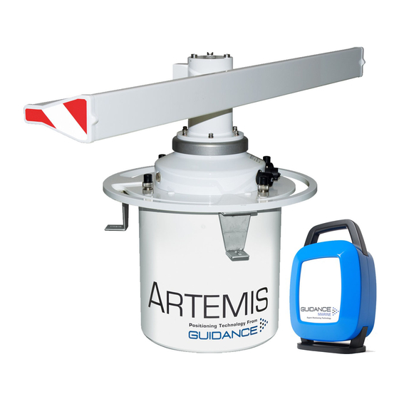
- Page 1 Artemis Mk6 Operator’s Guide featuring Artemis Dashboard with validation feature www.guidance.eu.com Guidance Marine Ltd, 5 Tiber Way, Meridian Business Park, Leicester LE19 1QP, UK T: +44 116 229 2600 E: sales@guidance.eu.com www.marine.direct...
- Page 2 Copyright © Guidance Marine Limited. All Rights Reserved. Copyright in the whole and every part of this document belongs to Guidance Marine Limited 0891 (the “Owner”) and may not be used, sold, transferred, copied or reproduced in whole or in part in any manner or form or in or on any media to any person other than in accordance with the terms of the Owner’s Agreement or otherwise without the prior written consent of the...
- Page 3 Document History Document Number Changes Issue Date 94-0440-4-A First release of Artemis Mk6 Operator’s Guide 28/06/2016 94-0440-4-B Artemis Mk6 Operator’s Guide (inclusion of Artemis Validator) 23/02/2017...
-
Page 4: Table Of Contents
Table of Contents Support Information Introduction Serial Numbers and Software Versions ..............28 System Overview ...................... 6 Network Communications Settings ................ 29 Getting Started Sensor Settings ...................... 30 Start Up and Shut Down ..................9 Using the On-Screen Keyboard ................31 Start Up.............................. - Page 5 Introduction Welcome to the Artemis Mk6 Operator’s Guide. It explains how to use the Artemis system once it has been fully installed. For instructions on how to install the system onto a vessel, refer to the document 94-0441-4 Artemis Mk6 Installer’s Guide.
-
Page 6: System Overview
This forces clean air into the housing of the antenna unit or beacon to prevent the ingress of explosive or flammable gases that might otherwise be ignited by electrical sparks. Contact Guidance Marine for details. An Antenna Unit (Mobile or Fixed Station) - Page 7 System Overview (Continued) System Operation Beacon Unit In order to provide positional data to the vessel’s DP system, the Artemis system needs to Used instead of a standard rotating Fixed Station on a fixed platform for absolute be “locked”. In this state, the antennae of the Fixed and Mobile Stations are facing each positioning, or on a moving platform or structure for relative positioning.
- Page 8 Getting Started This section covers the basics of using the Artemis system. It contains the following pages: • section on page 9 Start Up and Shut Down • Screen Contents section on page 10 • section on page 16 Display Options...
-
Page 9: Start Up And Shut Down
2. Double-click on the Artemis Dashboard icon. (Or run the Artemis Dashboard application from: Start > All Programs > Guidance Marine Ltd > Artemis > Artemis Dashboard). 3. The Dashboard display screen will appear. If the sensor is currently suspended, the main part of the screen will be greyed out. -
Page 10: Screen Contents
Screen Contents The Artemis Dashboard screen is split into three distinct sections, these are: • Main Screen and Bird’s Eye View (BEV) (see page 11) • (see page 13) Side Bar • (see page 15) Menu Pane Main Screen and Bird’s Eye View Dashboard Side Bar Menu Pane... -
Page 11: Main Screen And Bird's Eye View (Bev)
Screen Contents (Continued) Main Screen and Bird's Eye View (BEV) The circular BEV depicts the operational area of the Artemis system from above. The red dot at the centre represents the local Antenna Unit mounted on its vessel and the arc through which it can rotate corresponds to the combined blue areas. -
Page 12: System Status
Screen Contents (Continued) System Status This consists of two fields: Primary The primary part of the status display is in the upper-right corner of the Main Pane. It indicates the current status of the system: • System Running Normally • System Suspended •... -
Page 13: Side Bar
Screen Contents (Continued) Side Bar The Side Bar, the black pane to the left of the BEV, contains control and display After pressing the components in addition to the coordinates pane. Guidance button:... -
Page 14: Hotkey Buttons
Screen Contents (Continued) Hotkey Buttons Selecting the Hotkeys tab on the right-hand side of the Bird's Eye View (BEV) activates the Dashboard Hotkeys menu. The following keys - and the corresponding buttons on the Dashboard Hotkeys menu - act as shortcuts to application functions. -
Page 15: Menu Pane
Screen Contents (Continued) Menu Pane The Menu Pane, located across the bottom of the Dashboard screen, is not always visible. It appears when the Auto Search or Advanced buttons at the foot of the side bar are pressed, which causes the Main Screen to contract upwards. Clicking the same button for a second time causes the Menu Pane to disappear and the main screen to be restored to full size. -
Page 16: Display Options
Display Options Display View Screen Layout Mode To provide ample visibility during daytime operation and to limit glare during night shifts, the By default, the main area of the Dashboard screen contains the Bird’s Eye View (BEV) and Artemis Dashboard offers two display modes: Day View and Night View. In either mode the if the local and remote stations are locked, the positional coordinates are displayed in the brightness can be further adjusted by the Screen Brightness control. -
Page 17: Vessel Orientation
Display Options (Continued) Vessel Orientation To set Vessel Orientation: 1. Click on Advanced > Display Options > Screen Layout. The Artemis Dashboard supports four different arrangements of the Bird’s Eye View so that the operator can choose the one which best represents his surroundings. 2. -
Page 18: Basic Operation
Basic Operation In order for the Artemis system to output positional data to a vessel’s DP system, the local station needs to be tracking a remote station. This section explains how to achieve this. It contains the following pages: • section on page 19 Tracking Overview •... -
Page 19: Basic Operation Tracking Overview
Tracking Overview When an Artemis-equipped vessel moves within operating range of a remote station, the two stations will lock on to each other if the following conditions are met: • The correct remote station has been selected within the vessel’s Artemis Control Software (see Selecting a Remote Station on page 20). -
Page 20: Selecting A Remote Station
Selecting a Remote Station Although the local Artemis station tracks only one remote station at a time, it can be configured with a list of multiple prospective stations (see Artemis Mk6 Installer’s Guide). The side bar of the Dashboard screen displays the description of the currently selected remote station, its address code and the frequency pair used when the local station communicates with it. -
Page 21: Adjusting The Scan Sector
4. Click on the Apply (tick) button to confirm. Note that the scan sector cannot be narrower than 5°, nor can it extend into the dark grey area of the BEV (defined by the End Limits - see Artemis Mk6 Installer’s Guide). -
Page 22: Tracking Information Quality
Tracking Information Quality When the system is locked, the coordinates of the remote station and the strength of the signal received from it are displayed at the top of the side bar (or on the main screen if Coordinates Layout Mode has been selected). This data is colour coded: The colours denote signal strength: Red: -80dB to -62dB... -
Page 23: Dp Feeds
DP Feeds Up to four ports of the Artemis Control PC can be configured as DP Feed channels, in order to output positional data to the vessel’s DP system (see 94-0441-4 Artemis Mk6 Installer’s Guide). The state of each channel, its data format and the most recent data output can be viewed on the Dashboard. -
Page 24: Multi-Dashboard Artemis Systems
Multi-Dashboard Artemis Systems An Artemis system can include multiple PCs, each running the Dashboard program. At any given time all of the Dashboards may be in Monitoring Mode, or else one Dashboard – and only one – may be in Command Mode. This section explains the difference between the two modes and how to switch between them. -
Page 25: Multi-Dashboard Artemis Systems Artemis Dashboard - Command Mode
Artemis Dashboard – Command Mode It is necessary to run a Dashboard in Command Mode in order to use its system control functions (e.g. adjusting the scan sector or activating a different remote station). Any changes made in these areas will be evident on the screens of the monitoring Dashboards. On the other hand, display options such as screen brightness or vessel orientation can be set differently on each individual Dashboard, whether it is in Command or Monitoring mode. -
Page 26: Artemis Dashboard - Monitoring Mode
Artemis Dashboard - Monitoring Mode When the Dashboard is running In Monitoring Mode the controls relating to the Dashboard itself will be active, but those relating to other parts of the system will be disabled. Monitoring Dashboards display the same positional information as the Dashboard in Command, but cannot search for a remote station, activate a different one or suspend the local station. - Page 27 Support Information This section contains the following pages: • Serial Numbers and Software Versions on page 28 • on page 29 Network Communications Settings • on page 30 Sensor Settings • on page 31 Using the On-Screen Keyboard • on page 32 Working with Alarms •...
-
Page 28: Serial Numbers And Software Versions
Serial Numbers and Software Version Numbers are used to identify the hardware configuration and product revision of the Artemis system. They will be requested by Guidance Marine in the event of a support call to the company. Product Labels The Part Number and Serial Number for an Antenna Unit can be found on the product label fixed onto the base. -
Page 29: Network Communications Settings
5. Click on the Apply button (which is a green tick) to confirm. To Change the Comms Settings for the Artemis Sensor: Use the Service Interface (see the Artemis Mk6 Installer’s Guide); the Artemis Sensor panel on the Comms Settings pane of the Dashboard is for information only. -
Page 30: Sensor Settings
Automatic causes the power mode to be automatically switched between Normal and Reduced depending on the current range between the stations. Guidance Marine recommend that the power mode is set to automatic. Anti-Icing When this is set to Auto and the temperature falls towards freezing point, the heating inside the Artemis antenna will automatically be switched on. -
Page 31: Using The On-Screen Keyboard
Using the On-Screen Keyboard The Artemis Dashboard provides an On-Screen Keyboard (OSK), which allows text to be input using a mouse, trackball or touch screen. To enable the on-screen keyboard The OSK will already be enabled if you selected this option during installation of the Dashboard. -
Page 32: Working With Alarms
Working with Alarms Filtering Alarms During operation the Artemis system produces an audit trail of event messages. These range in increasing order of severity from: Information, Warning, and Error to Fatal. As A filter is available to suppress the display of particular alarm types. By default, the filter is these alarms are raised, the Dashboard lists them within the Alarms Pane. - Page 33 Working with Alarms (Continued) Using the Current and Historic Alarms Tabs There are two tabs on the Alarms pane, each containing a list of alarms: • The Current Alarms tab displays new alarms (raised since the Dashboard was last opened). •...
-
Page 34: Artemis Validator
Artemis Validator (Permanently Installed) -
Page 35: Using A Permanently Installed Artemis Validator
Using a Permanently Installed Artemis Validator The Validator tab is used to verify the performance of the Artemis Sensor using an installed During the Validation: • Artemis Validator. This is a device, mounted on the vessel, which can emulate a second The Connection to the Artemis Sensor is checked. - Page 36 Using an Artemis Validator (Continued) Validator Log Entries Validate Operations can have the following kinds of outcome: Each Validate Operation will generate a log entry, indicating the success or failure of each operation. Validate Operations can have the following kinds of outcome: Validate Outcomee Details...
-
Page 37: Additional Information
Additional Information This section contains the following pages: • on page 38 International Standards Compliance • on page 39 System Specifications... -
Page 38: International Standards Compliance
Web: www.maritimradio.no Web: www.maritimradio.no Authorisation by the Federal Communications Commission for the use of Artemis Mk6 Authorisation by the Federal Communications Commission for the use of Artemis Mk6 equipment in the United States of America is pending. FCC ID: VYMARTEMIS. -
Page 39: System Specifications
System Specifications Antenna Unit (Mobile and Fixed Station) Frequency Azimuth Measurement Frequency band 9200 - 9300 MHz Range 360° Four fixed, user-selectable frequency pairs Pair Mobile Station Fixed Station Display resolutions 0.1 on Dashboard 0.01 on Artemis Service Interface 9200 MHz 9230 MHz Data update rate 0.25s... - Page 40 9300 MHz 9270 MHz 9230 MHz 9200 MHz 9270 MHz 9300 MHz Range (semi-omni directional antenna) 10m – 1500m range Supply voltage 220-240 VAC, 50-60 Hz Guidance Marine reserves the right to alter or amend this published specification without notice.
-
Page 41: Index
Index Filtering Alarms 32 Radial Markers 11 Additional Information 37 Remote Station 18, 19, 20 Alarms 32 Guidance Button 9, 13, 16, 20, 21, 25, 26 Resume Button 9, 25 Antenna Units 6 Guidance Home Menu 9, 13, 16 Anti-Icing 30 Scan Sector 11, 21 Historic Alarms 33 Screen Layout Mode 16...
Need help?
Do you have a question about the Artemis Mk6 and is the answer not in the manual?
Questions and answers