Table of Contents
Advertisement
ATOMLAB 950 (PC)
MEDICAL SPECTROMETER
SERVICE/OPERATION MANUAL
187-130
187-135
187-140
187-145
B
IODEX
FN: 05-211 6/05
Biodex Medical Systems, Inc.
20 Ramsay Road, Shirley, New York, 11967-4704, Tel: 800-224-6339 (In NY and Int'l, call 631-924-9000), Fax: 631-924-9241, Email: sales@biodex.com, www.biodex.com
Advertisement
Table of Contents

Related Manuals for biodex ATOMLAB 950


Summary of Contents for biodex ATOMLAB 950
- Page 1 ATOMLAB 950 (PC) MEDICAL SPECTROMETER SERVICE/OPERATION MANUAL 187-130 187-135 187-140 187-145 IODEX FN: 05-211 6/05 Biodex Medical Systems, Inc. 20 Ramsay Road, Shirley, New York, 11967-4704, Tel: 800-224-6339 (In NY and Int’l, call 631-924-9000), Fax: 631-924-9241, Email: sales@biodex.com, www.biodex.com...
- Page 2 115 VAC, Mobile, Thyroid Uptake System, Atomlab 950 #187-145 230 VAC, Mobile, Thyroid Uptake System, Atomlab 950 NOTE: All or some of the following symbols, cautions, warnings and notes may apply to your Atomlab 950 and correspond to this operation manual: Symbol Meaning Attention, consult accompanying documents.
- Page 3 ATOMLAB Thyroid Uptake Systems carry the industry’s best warranty. Biodex Medical Systems backs Atomlab Thyroid Uptake Systems with a truly comprehensive full two-year warranty. It covers both parts and labor, and includes all unit elements. Biodex’s two-year warranty is a sure sign of product quality and dependability.
-
Page 4: Table Of Contents
TABLE OF CONTENTS 1. Introduction ........................1-1 2. Setup Instructions......................2-1 • Assembly Procedure ......................2-1 • System Shut-Down......................2-7 • General Cleaning Instructions ..................2-7 • Power-Up and Self-Test ....................2-7 • Computer Preliminaries ....................2-8 • System-Wide Icons......................2-8 • System Software Setup ....................2-13 • Edit Physicians and Technologist Database..............2-15 •... - Page 5 1. INTRODUCTION 9. Hematology ........................9-1 • The Hematology Patient Page ..................9-1 • IHSA I-125 ........................9-1 • Cr-51 Blood Volume......................9-3 • Cr-51 Red Cell Survival ....................9-9 • GFR ..........................9-11 • Effective Renal Plasma Flow ....................9-17 Appendix A: Isotope Efficiency Calculation ................A-1 Appendix B: Specifications ....................B-1 Appendix C: Electromagnetic Compatibility ..............C-1 Schematics..........................S-1...
-
Page 6: Introduction
1. INTRODUCTION The Atomlab 950 PC is a complete thyroid uptake and analysis system specifically designed for nuclear medicine. Capable of performing a full range of studies this system provides fast, accurate results for Uptake Studies, Bioassay, Wipe Testing, Schilling Tests programmed for the Mallinckrodt, Bracco, or Nycomed Dicopac®... -
Page 7: Setup Instructions
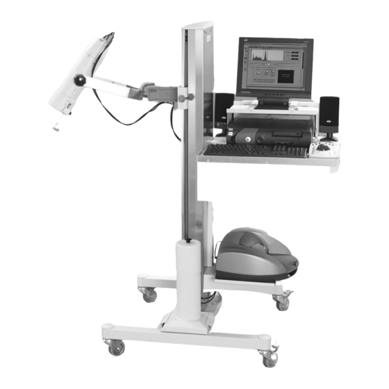
2. SETUP INSTRUCTIONS Assembly Procedure (See Figures 2-1 and 2-2.) Tools Required: Knife Wire cutter Phillips screwdriver Medium straight screwdriver Small straight screwdriver 1/32" Allen key (included) Adjustable wrench Remove the uptake stand from its shipping box and place in an area suitable for assembly and setup. Determine how the unit will be positioned in the department where it is to be used. - Page 8 1. INTRODUCTION Figure 2-1. The MCA Uptake Stand. SETUP INSTRUCTIONS...
- Page 9 CONTENTS 11. Connect the two well counter cables to the well counter fittings. The larger connector (MHV) should be connected to the high voltage fitting on the well. The smaller connector (BNC) connects to the well signal fitting. Allow the ends of both cables to lie off to the side. 12.
- Page 10 1. INTRODUCTION Figure 2-2. The MCA Uptake Stand. (side view). SETUP INSTRUCTIONS...
- Page 11 CONTENTS 24. Remove the tube assembly and base from its packaging. Notice that a grounding strap is wrapped around the base and tube assembly. This is necessary to properly ground the detector shroud to the base and stabilize the count rate. Remove the red protective cap from the detector and carefully insert the detector and base assembly into the cone shaped collar.
- Page 12 CONTENTS 38. Locate the printer cable that now protrudes from the large shelf side cable hole and plug it into the CPU printer port. 39. Unpack the speakers and place them on the large shelf. Connect the double cable from the rear of the CPU speaker connector (the connector next to the 9-pin DIN connector.) 40.
-
Page 13: System Shut-Down
1. INTRODUCTION SYSTEM SHUT-DOWN The Atomlab 950 system is now fully set up and ready for operation. Before it can be moved, however, it must be shut down using the following procedure. At the Windows Desktop screen, which should now be displayed, move the trackball pointer over the “Atomlab950”... -
Page 14: Computer Preliminaries
• Display of software/firmware revisions NOTE: To view a video clip about the Biodex Company, you can at this point click on <About Biodex>. Once the self-test is complete, the system highlights <OK>. Click on <OK> to automatically advance to the MCA Operation screen. - Page 15 1. INTRODUCTION Figure 2-3. Click <OK> on the About Atomlab 950 Screen to Begin the Self-Test. SETUP INSTRUCTIONS...
- Page 16 1. INTRODUCTION Figure 2-4. The Atomlab 950 PC Operation Screen is displayed at completion of the self-test. The system is now ready for use. SETUP INSTRUCTIONS 2-10...
- Page 17 File: Under the File screen, the printer set up button allows you to set up the printer that you are using. The Atomlab 950 uses either DeskJet 694C, 845 or 810C software. The version used is dependent on the Hewlett Packard printer. We recommend using the 694C printer driver. If a different printer is being used, follow the instructions for setting up under Windows.
- Page 18 1. INTRODUCTION Menu Bar Primary Tool Bar Screen Tool Bar Figure 2-5 The Isotope Editing Screen. SETUP INSTRUCTIONS 2-12...
-
Page 19: System Software Setup
To exit Simulation mode, click on the <X> in the upper right corner of the screen to return to the desktop. You can then turn the MCA box ON and double-click on the Atomlab 950 desktop icon to access the Atomlab 950 Active mode. - Page 20 1. INTRODUCTION Figure 2-6. The System Setup Screen. SETUP INSTRUCTIONS 2-14...
-
Page 21: Edit Physicians And Technologist Database
Preferences Check any option here to activate. • Numerical Data: If checked, allows the operator to change the time and data of administration as well as change the count before it is saved in a mode. For example: If you count background and uptake before you save, you can go in and modify this value. - Page 22 1. INTRODUCTION Figure 2-7. The Edit Physicians and Technologists Information Screen. SETUP INSTRUCTIONS 2-16...
-
Page 23: Database Manager
AVI Path This shows the current directory path of the computer files in use. Leave this setting at the default value. DATABASE MANAGER (Refer to Figure 2-8.) The Database Manager portion of the program allows patient information, procedures specifications or isotope information to be saved to a floppy diskette or other information storage format. - Page 24 To Remove Data: To remove data in the bottom hand box, click on <Remove>. Highlight the data or item in the right hand box that you wish to remove. Click on <Remove> and a pop-up window will ask if you really want to remove this data. If you do, click <Yes>...
- Page 25 1. INTRODUCTION Figure 2-8. The Database Manager Screen. 2-19 SETUP INSTRUCTIONS...
-
Page 26: Administration
3. ADMINISTRATION Before using the Atomlab 950 PC for counting purposes, it is important that you take a few minutes and prepare the system for operation. The following functions are set from the Operation screen and control the system throughout the different program modes. - Page 27 The multi-channel analyzer in the Atomlab 950 has several fixed precision gains and a regulated high voltage supply. The pulse shapes are digitized and then processed by a high speed digital signal processor.
- Page 28 CONTENTS Figure 3-1. The Calibration Screen. ADMINISTRATION...
- Page 29 1. INTRODUCTION Figure 3-2. A Calibration Report. ADMINISTRATION...
-
Page 30: High Voltage Adjustment
CONTENTS Calibration Screen Description Multi-channel analyzer display: This display has a scale on the left side showing counts full scale. On the bottom is the scale that shows the ROI. ROI Counts: To the right of the MCA display is a box showing ROI counts for region of interest counts, ROI cpm and time. - Page 31 1. INTRODUCTION Figure 3-3. The High Voltage-Adjustment Screen. ADMINISTRATION...
- Page 32 1. INTRODUCTION Figure 3-4. The High Voltage Report. ADMINISTRATION...
-
Page 33: Chi-Square
1. INTRODUCTION Once a High Voltage Adjustment is started, it will run until it is completed unless you choose to abort. When it is completed, the system will inform you and then shift to the other detector to allow you to do another high voltage adjustment if desired. Click on <Continue>... - Page 34 1. INTRODUCTION Figure 3-5. The Chi-Square Screen ADMINISTRATION...
- Page 35 1. INTRODUCTION Figure 3-6. The Chi-Square Report. ADMINISTRATION 3-10...
-
Page 36: Administration Report
Press <Print> to print the report. This brings up the printer screen. Click on <OK> to print. NOTE: The High Voltage Report and the Atomlab 950 Administration Report are similar. The Atomlab 950 Administration Report includes Chi-Square results, the High Voltage Report does not include the Chi-Square results. - Page 37 1. INTRODUCTION Figure 3-7. An Administration Report. ADMINISTRATION 3-12...
- Page 38 CONTENTS To select another isotope from the Isotope Editing screen, click on <Open>. A list of isotopes will be displayed. Highlight the desired isotope from the Isotope List and click <Select>. The new isotope is now displayed in the Isotope Name box. All information on the Isotope Editing screen now reflects the new isotope.
- Page 39 1. INTRODUCTION Figure 3-8. The Isotope Editing Screen. ADMINISTRATION 3-14...
- Page 40 1. INTRODUCTION Figure 3-9. The Select Isotope Window. 3-15 ADMINISTRATION...
-
Page 41: Isotope Efficiencies
For the well it is the inside diameter, which on the well shipped by Biodex, is 1.905cm. Factory set well depth is 2.54cm. This depth in the well would be indicative of many wipes where the center of the activity or where the wipe would be located when lowered into the well. - Page 42 1. INTRODUCTION Figure 3-10. The Detector Efficiency Screen. 3-17 ADMINISTRATION...
-
Page 43: Detector Efficiency
CONTENTS DETECTOR EFFICIENCY To Enter A Detector Efficiency From any screen, click on the <Isotope> icon in the primary tool bar. The Isotope Editing screen will be displayed. Click on <Detector Efficiency> at the bottom of the screen. The Detector Efficiency screen will be displayed. - Page 44 1. INTRODUCTION Figure 3-11. The Geometric Efficiency Window. 3-19 ADMINISTRATION...
-
Page 45: Spectrum Analysis
CONTENTS Click <Calculate Efficiency>. A window will be displayed telling you to prepare to count Background. Ensure there are no isotopes in the area before you click <OK>. Once you click on <OK>, the system will proceed to count for 100 seconds. When it is done counting, a menu will be displayed telling you to place an isotope at the proper distance from the detector and to click <OK>... - Page 46 1. INTRODUCTION To choose a different isotope, click on Set Window and highlight the desired isotope from the isotope list. The window will switch to that keV setting and display it. NOTE: The >> button to the right of the Set Window can be used to cycle through the isotope list while displaying the regions of interest for all the factory and custom isotopes that are stored in memory.
-
Page 47: How Is Roi Determined
Example Tc-99m has a peak energy of 140 keV according to the radionuclide decay scheme. The Atomlab 950 uses a default of +/- 15% energy window around the peak energy. These values calculate to be 119 keV to 162 keV and are displayed on the Isotope Editing page. - Page 48 1. INTRODUCTION Figure 3-13. A Spectrum Analysis Report. 3-23 ADMINISTRATION...
-
Page 49: Thyroid Uptake
Each of the data sets that are counted are displayed in the status window on the Thyroid Uptake screen. NOTE: If you have not yet calibrated your Atomlab 950 on this day, the system will prompt you to calibrate before proceeding with the Thyroid Uptake or any other mode selected. - Page 50 1. INTRODUCTION Figure 4-1. The Procedure Definition Screen. THYROID UPTAKE...
- Page 51 1. INTRODUCTION Figure 4-2. The Patient Definition Screen. THYROID UPTAKE...
-
Page 52: Patient Definition Screen
1. INTRODUCTION The Patient Definition Screen (See Figure 4-2.) On this page, the user can add a new patient, edit existing patient information or select an existing patient to study. All pertinent information regarding the patient is displayed on this page. Fields are provided for the Patient Name, Identification Number, Address, Phone Number, Height, Weight, Sex, Date of Birth. -
Page 53: Determining Automatic Count Time
CONTENTS NOTE: If there is an existing patient and at some future time another uptake study with a new dose will be administered, you would go to the Patient Definition screen, select the desired patient, and either select an existing study or click on <Add Test To Selected Patient>. This allows the addition of a new test to the selected patient. - Page 54 CONTENTS Maximum Count Time All of the following examples had a 60 sec maximum count time set in the Uptake SETUP loop. The first example did not require longer than 60 seconds on each measurement to satisfy the 98% accuracy requirement.
-
Page 55: Performing A Thyroid Uptake
1. INTRODUCTION Comment The uptake was about one fourth the values as in example 1 in order to illustrate the change in counting time required for uptake and patient background. If the maximum set count time was 120 seconds, then the actual counting times for the thyroid and patient background would have been 119 and 81 seconds respectively. - Page 56 1. INTRODUCTION Figure 4-3 The Thyroid Uptake Screen. THYROID UPTAKE...
- Page 57 INTRODUCTION Definition> in the primary tool bar. After selecting a patient, you can then access any mode of operation with the new patient selected. For existing patients, click on the patient name to reveal the studies. Double-click on the desired study to return to the Thyroid Uptake screen with the patient and study selected.
- Page 58 1. INTRODUCTION Figure 4-4. A Thyroid Uptake Report. THYROID UPTAKE 4-10...
- Page 59 1. INTRODUCTION Figure 4-5. A Time Activity Report. 4-11 THYROID UPTAKE...
-
Page 60: Printing A Thyroid Uptake Report
CONTENTS Uptake Is Complete" and prompts you to save the results. If you click <Yes> the results are stored and cannot be changed. If you click <No> and do not save the results, the system allows you to recount the thyroid and patient background. - Page 61 1. INTRODUCTION After saving a Thyroid Uptake as described above, click on the <Report> icon in the primary tool bar. The Report Generation screen should be displayed. Click on the desired parameters, including Time/Activity for Thyroid Uptake, then key in the Technologist name, dose activity and any comments to be printed on the report.
-
Page 62: Manual Mode
5. MANUAL MODE The MCA Manual mode is used as a rate counter that functions in either a Preset Time, Preset Count or Continuous Counting mode. You can press Spectrum for any count that you take in this mode and create reports from the data obtained. - Page 63 1. INTRODUCTION Figure 5-1. The Manual Mode Screen. MANUAL MODE...
- Page 64 1. INTRODUCTION Figure 5-2. A Manual Mode Report. MANUAL MODE...
-
Page 65: Wipe Test
6. WIPE TEST (See Figures 6-1 - 6-5.) The Wipe Test is used to determine the DPM of swipes taken in the designated areas of a department using the optional well counter Model #187-246. A total of 10 swipes may be identified and counted for each area. - Page 66 1. INTRODUCTION Figure 6-1. The Wipe Counting Screen. WIPE TEST...
- Page 67 CONTENTS Figure 6-2. The Wipe Area Setup Screen. WIPE TEST...
- Page 68 CONTENTS Figure 6-3. The Wipe Preferences Window. WIPE TEST...
-
Page 69: Select Wipe
1. INTRODUCTION In the Available Isotopes list, highlight an isotope and click on <Add to Area>. The isotope name will now be displayed in the lower box. If desired, highlight additional isotopes on the Isotope List and add them to the lower box. To remove an isotope from the box, highlight the isotope in the lower box and click on <Remove From Area>. - Page 70 1. INTRODUCTION Figure 6-4. The Background LLD Screen. WIPE TEST...
-
Page 71: Wipe Preferences
CONTENTS Double-Click on the desired wipe area to select the wipe, or highlight the wipe and click on <Select>. The system returns to the Wipe Counting screen with the selected wipe now displayed in the Wipe Area Name box. NOTE: If you click <Close> on the Wipe Area Selection List, the system returns to the Wipe Counting screen with the original wipe still selected. - Page 72 1. INTRODUCTION Figure 6-5. The Wipe Results Report. WIPE TEST...
-
Page 73: Performing A Wipe Test
1. INTRODUCTION Once the background count is completed, the Background and LLD screen displays the results. Click on <OK> to accept the results and return to the Wipe Counting screen. If the results are not click on <Background> again and perform another background. acceptable, NOTE: <Estimate LLD>... -
Page 74: Bioassay
7. BIOASSAY This mode is used to verify any Iodine 131, 123 or 125 concentration for staff or a patient who have direct contact with radioactive iodine or radioactive patients. A record may then be printed out for an individual, as a Bioassay History, or as a Bioassay Employee Summary. NOTE: In Bioassay and Wipe Test mode, the activity shown is NET activity. -
Page 75: To Perform A Bioassay
CONTENTS To Perform A Bioassay Click on <Patient Definition> in the primary tool bar. Select an existing patient, edit an existing patient, or create a new patient to test. Click on <Close> to return to the Operation screen. Click on <Bioassay>. The Bioassay screen should now be displayed. The selected patient should be displayed in the Select Name box along with the proper patient I.D. - Page 76 1. INTRODUCTION Figure 7-2. The Bioassay Preferences Screen. BIOASSAY...
- Page 77 CONTENTS NOTE: If you change the trigger level, the new amount is used for all new tests. 13. After assaying a patient or staff member and accepting the count, press <Save> to save the information.. NOTE: When you wish to perform an additional assay for this patient, click on <Parameters> and then click on <New Test>.
- Page 78 CONTENTS Figure 7-3. An Individual Bioassay Report. BIOASSAY...
- Page 79 CONTENTS Figure 7-4. An Employee Bioassay Summary. BIOASSAY...
- Page 80 1. INTRODUCTION Figure 7-5. An Individual Bioassay History Summary. BIOASSAY...
-
Page 81: Schilling Tests
8. SCHILLING TESTS In this mode, Schilling tests using the standard commercial kits Mallinckrodt - Bracco and Dicopac have been programmed into the system. Before use, the operator should go to the Procedure Definition Window, select the kit style used in the facility, and set-up or verify that the counting time, correction factor and sample volumes are correct for the procedure. - Page 82 1. INTRODUCTION Figure 8-1. Defining a Facility Standard Schilling Test. SCHILLING TESTS...
- Page 83 CONTENTS Figure 8-2. The Schillings Counting Page. SCHILLING TESTS...
- Page 84 CONTENTS Figure 8-3. A sample Schillings Mallinckrodt Report. SCHILLING TESTS...
-
Page 85: Schilling Dicopac
CONTENTS Click on the <Preferences> button and then enter a total urine volume for the patient that you are testing. Once you have entered the total volume, click <OK>. You can now proceed with counting. NOTE: You can change the sample volume, correction factor and count time for this study in the parameters window. - Page 86 CONTENTS To Perform a Dicopac Schillings Test: (See Figure 8-4.) 1. Click on the <Procedure> icon to access the Procedure Definition window. 2. At the Procedure Definition window, enter the parameters for the Dicopac studies that you wish to perform. You can modify an existing procedure or create a new procedure. This entails entering the counting time, sample volume, detector and type of kit.
- Page 87 CONTENTS Figure 8-4. The Diopac Schillings Counting Page. SCHILLING TESTS...
- Page 88 CONTENTS Figure 8-5. A Sample Diopac Schillings Report. SCHILLING TESTS...
-
Page 89: Hematology
9. HEMATOLOGY In the Hematology Mode there are a number of different programs that can be used. All are based on commercially available kits. The programs include IHSA I-125, Cr-51 Blood Volume, Cr-51 Red Cell Survival, Glomerular Filtration Rate (GFR) and Effective Renal Plasma Flow (ERPF). The Hematology Patient Page (See Figure 8-1.) Setting Up For Hematology... - Page 90 CONTENTS 9-1. The IHSA Counting Page. HEMATOLOGY...
-
Page 91: Cr-51 Blood Volume
CONTENTS Click on <Plasma Sample> to begin counting the plasma sample. When done counting, the system displays the plasma sample counts and count rate. When it is done counting the plasma sample, the system will display the "Verified Test Complete" window, asking if you want to permanently save the data. - Page 92 1. INTRODUCTION Figure 9-2. A Sample IHSA I-125 Test Report. HEMATOLOGY...
- Page 93 CONTENTS Figure 9-3. The CR-51 Counting Page. HEMATOLOGY...
- Page 94 CONTENTS 8. When it is done counting the plasma sample, the system will display the "Verified Test Complete" window, advising that the test is complete and you can now permanently save the results in the database. If you are satisfied with the results and the tests, click <Yes> to permanently save. If you wish to recount any one of the items, click <No>.
- Page 95 CONTENTS Figure 9-4. A Sample Cr-51 Volume Test Report. HEMATOLOGY...
- Page 96 CONTENTS Figure 9-5. The Cr-51 Red Blood Cell Survival Counting Page. HEMATOLOGY...
-
Page 97: Cr-51 Red Cell Survival
CONTENTS Cr-51 Red Cell Survival (See Figures 9-5 and 9-6.) To set up as the standard number of samples and the count time, click on the <Procedure Definition> icon in the primary tool bar and then enter the red cell survival maximum number of samples and counting time. - Page 98 CONTENTS Figure 9-6. A sample Cr-51 Survival Test Report. HEMATOLOGY 9-10...
-
Page 99: Gfr
CONTENTS (See Figure 9-7.) The following test is for the Glomerular Filtration Rate (GFR) test. This test uses Technetium-99m - DTPA as the pharmaceutical. The GFR test is a renal function test of the kidneys. The procedure followed is from the Journal of Nuclear Medicine Technology, Volume 14, Number 4, December 1986, entitled, "Technical Aspects of a New Technique for Estimating Glomerular Filtration Rate Using Technetium-99m - DTPA"... - Page 100 CONTENTS Figure 9-7. The GFR Counting Page. HEMATOLOGY 9-12...
- Page 101 CONTENTS 11. The "Verified Test Complete" window should now be displayed. Click <Yes> if you wish to permanently save the results, or <No> if you do not want to save and would like to have the ability to recount any of the various items counted or change the times. 12.
- Page 102 CONTENTS patient. Click <OK>. 13. The "Verified Test Complete" window should now be displayed. Click <Yes> if you wish to permanently save the results, or <No> if you do not want to save and would like to have the ability to recount any of the various items counted or change the times.
- Page 103 1. INTRODUCTION Figure 9-8. A One Sample Glomerular Filtration Rate Report. 9-15 HEMATOLOGY...
- Page 104 1. INTRODUCTION Figure 9-9. A Two Sample Glomerular Filtration Rate Report. HEMATOLOGY 9-16...
-
Page 105: Effective Renal Plasma Flow
Effective Renal Plasma Flow (ERPF) (See Figure 9-10 and 9-11.) The ERPF procedure in the Biodex Medical Spectrometer is based on the Journal of Nuclear Medicine, Volume 30, Number 12, December 1989, entitled, "Estimation of Technetium-99m-MAG3 Plasma Clearance in Adults From 1 or 2 Blood Samples" by Charles D. Russell, Andrew Taylor and Dennis Eshima, Div. - Page 106 1. INTRODUCTION Figure 9-10. The ERPF Counting Page. HEMATOLOGY 9-18...
- Page 107 CONTENTS The following procedures are for counting and getting results for the ERPF study. From the <Patient Definition> window, choose ERPF as the study that will be performed. This can be done with either a new patient or an existing patient. At the counting page, verify that the patient and patient ID# are correct.
- Page 108 1. INTRODUCTION Figure 9-10. The ERPF Counting Page. HEMATOLOGY 9-20...
- Page 109 1. INTRODUCTION Figure 9-11. An Effective Renal Plasma Flow Report. 9-21 HEMATOLOGY...
-
Page 110: Appendix A: Isotope Efficiency Calculation
For X = 0.75", G.E. = 20.0% NOTE: The Atomlab 950 is shipped with the Isotope Efficiency screen set to centimeters (see page 3-12 and Figure 3-10). The system can be set to centimeters, inches or any other unit of measure, as long as it is consistent for the diameter and distance. - Page 111 The Atomlab 950 is shipped with the Isotope Efficiency screen set to centimeters (see pages 3-12 and Figure 3-10). The system can be set to centimeters, inches or any other unit of measure, as long as it is consistent for the diameter and distance.
- Page 112 Mode “Isotope Efficiency” page of the Atomlab 950. D. Efficiency Measurement Make sure the Atomlab 950 has a current Cs-137 calibration. Then go to the “Isotope Efficiency” page. Use the arrow keys <previous> or <next> to display the isotope you wish to set the efficiency for.
- Page 113 1. INTRODUCTION 10. Calculate the composite efficiencies D.E. * G.E. using one of the following equations: (S - B) counts * 100% D.E. * G.E. = (T-t) * 37000 µCi dps/µCi (S - B) counts * 100% D.E. * G.E. = current activity displayed S and B are defined in steps 7 and 8 under Efficiency Measurement.
- Page 114 CONTENTS Example Calculation: Determine the detector efficiency of Am-241 in a well detector with an opening of 0.625 inches and the source located in the well at 1 inch below the surface. Geometric Efficiency for a Well: I.D. = 0.625 inches X - 1.00 inch G.E.
- Page 115 E. Analytically Determined (Theoretical) Detector Efficiencies The following table of 25 isotopes contains analytically determined efficiency values for use with this instrument. Stated with the efficiency value is lower and upper region of interest for which the efficiency is valid. In the wipe test program, these ROI’s are fixed and cannot be adjusted. Therefore, these efficiency values may be used in the wipe test program of this instrument instead of empirically determining the efficiency for each isotope.
- Page 116 1. INTRODUCTION The Detector Efficiency (D.E.) has been calculated for both probe and well detectors. There is a difference because the photon path length through the Nal detector is different in the two detector configurations. There are some isotopes that the well efficiency has not been analytically determined due to gamma ray summing in the well.
-
Page 117: Appendix B: Specifications
APPENDIX B SPECIFICATIONS • Industry exclusive two-year warranty MEDICAL SPECTROMETER HARDWARE Computer: Atomlab 950PC: PC for Windows XP with P4, 2.8 GHz processor, 256 megabyte RAM, 40 gig HD, 24x CD-RW and 3.5" floppy drive. ® Equipped with: 15" Flat Color Monitor, Sound Card and Speakers, Standard Keyboard, Trackball and Hewlett- Packard Desk Jet Printer. -
Page 118: Appendix C: Electromagnetic Compatibility
EMC information provided in the ACCOMPANYING DOCUMENTS. See accompanying chart. NOTE: Portable and mobile RF communications equipment can affect MEDICAL ELECTRICAL EQUIPMENT. NOTE: Contact Biodex Medical Systems, Inc. for additional EMC information. Standard Test Method... -
Page 119: Schematics
SCHEMATICS Schematics provided on the following pages include: • Schematics Controller • Schematics MCA, ‘95 • Assembly, PC Board, PC Based Spectrometer 950 and 950CE • Assembly, PCB, MCA SCHEMATICS...
Need help?
Do you have a question about the ATOMLAB 950 and is the answer not in the manual?
Questions and answers