Table of Contents
Advertisement
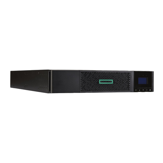
HPE R/T2200 G5 UPS, R/T3000 G5 UPS,
and ERM
User Guide
Abstract
This document is for the person who installs, administers, and troubleshoots power products.
Hewlett Packard Enterprise assumes you are qualified in the servicing of high-voltage
equipment and trained in recognizing hazards in products with hazardous energy levels.
Part Number: 881628-001a
June 2018
Edition: 2
Advertisement
Table of Contents

Related Manuals for Hewlett Packard Enterprise R/T2200 G5


Summary of Contents for Hewlett Packard Enterprise R/T2200 G5
- Page 1 Abstract This document is for the person who installs, administers, and troubleshoots power products. Hewlett Packard Enterprise assumes you are qualified in the servicing of high-voltage equipment and trained in recognizing hazards in products with hazardous energy levels. Part Number: 881628-001a...
- Page 2 Enterprise products and services are set forth in the express warranty statements accompanying such products and services. Nothing herein should be construed as constituting an additional warranty. Hewlett Packard Enterprise shall not be liable for technical or editorial errors or omissions contained herein.
- Page 3 0 to 40°C/32 to 104°F , free of conductive contaminant. • For HPE R/T3000 HV NA/JP and HPE R/T3000 G5 INTL UPS models: FCC/EN55022 Class B IEC62040-2 C1. • For HPE R/T2200 G5 NA/JP and HPE R/T3000 G5 LV NA/JP UPS models: FCC/EN55022 Class A, IEC62040-2 C2 Certification Standards • UPS directives: UL 1778 (UL listed).
- Page 4 Personal Safety • The system has its own power source (the battery). Consequently, the power outlets may be energized, even if the system is disconnected from the AC power source. • Dangerous voltage levels are present within the system. The system should be opened exclusively by qualified service personnel.
-
Page 5: Table Of Contents
5.3 Battery module replacement ..................28 5.4 Spares ..........................29 6. Technical Specifications..................30 6.1 HPE R/T2200 G5 NA/JP UPS and HPE R/T3000 G5 LV NA/JP UPS ......30 6.2 HPE R/T3000 G5 HV NA/JP UPS and HPE R/T3000 G5 INTL UPS......31 6.3 Glossary ..........................32 7. -
Page 6: Overview
Follow all local regulations for the disposal of packing materials. End of life Hewlett Packard Enterprise processes products at the end of their service lives in compliance with local regulations. Hewlett Packard Enterprise works with companies in charge of collecting and eliminating our products at the end of their service lives. -
Page 7: Weights And Dimensions
Description Weights Dimensions (in/mm) (lb/kg) D x W x H HPE R/T2200 G5 NA/JP UPS 30.5 / 67.2 20.6 x 17.4 x 3.4 / 523 x 442 x 86 HPE R/T3000 G5 LV NA/JP UPS 39.9 / 88.0 25.4 x 17.4 x 3.4 / 645 x 442 x 86 HPE R/T3000 G5 HV NA/JP UPS 38 / 83.8... -
Page 8: Rear Panels
USB communication port 1.3 Rear panels RS-232 communication port Connector for automatic recognition of an additional battery module HPE R/T2200 G5 NA/JP UPS Slot for optional communication card Connector for ROO (remote on/off) or RPO (remote power off) control Connector for additional battery... -
Page 9: User Interface
2. User Interface 2.1 Control panel The UPS has a five-button graphical control panel. Power On On battery Alarm Indicator (green) Indicator (yellow) Indicator (red) Normal mode 100% 100% 2.7kW 17min 3kVA 1ERM E ciency: ~98% Escape Down Enter On/Off button The following table shows the indicator status and description: Indicator Status Description... -
Page 10: Lcd Window
2. User Interface 2.2 LCD window The LCD window provides information about the UPS, load status, events, measurements, and settings. As the default, or after five minutes of inactivity, the LCD displays the screen saver. The backlight LCD automatically dims after 10 minutes of inactivity. Press any button to restore the screen. Operation Status Normal mode 100% 100%... -
Page 11: Display Functions
2. User Interface 2.3 Display functions Press the button to activate the menu options. Use the buttons to scroll through the menu structure. Press the button to select an option. Press the button to cancel or return to the previous menu. - Page 12 2. User Interface Description Available settngs Default settings Output voltage* [100V] [120V] [125V] User selectable when UPS is On INTL models: [200V] [208V] [220V] powered the first time. [230V] [240V] *IMPORTANT: The output voltage of the UPS must be set to the same nominal voltage as the facility input voltage for optimum UPS performance.
- Page 13 2. User Interface Description Available settngs Default settings Cold start [Disable] [Enable] Enable Enables or disables the product to start on battery. The first cold start is always disabled. Forced reboot [Disable] [Enable] Enable If power returns during a shutdown sequence: If enabled, the shutdown sequence will complete and there is a 10...
-
Page 14: Installation
3. Installation 3.1 Unpacking and contents verification HPE R/T2200 G5 NA/JP UPS and HPE R/T3000 G5 LV NA/JPN UPS (1) HPE R/T2200 G5 NA/JP and HPE R/T3000 G5 LV (5) Documentation NA/JPN (6) Mounting brackets, rails, and hardware (2) Bezel parts... - Page 15 3. Installation HPE R/T3000 G5 HV NA/JPN UPS and HPE R/T3000 G5 INTL UPS (8) HPE R/T3000 G5 HV NA/JPN and HPE R/T3000 G5 (13) Two cable locking systems INTL (14) Documentation (9) Connection cable to AC power source (15) Mounting brackets, rails, and hardware (L6-20P for NA/JP model.
-
Page 16: Battery Module Connection
3. Installation 3.2 Battery module connection CAUTION: This operation must be performed when the UPS is switched off and unplugged from the AC source. Do not disconnect the connector while the unit is operating from the AC source or in reserve mode. NOTE: Before starting the UPS, connect the internal battery. -
Page 17: Tower Installation
3. Installation 3.3 Tower installation 3.4 Rack installation WARNING! To reduce the risk of personal injury or damage to the equipment, be sure that: • The leveling feet are extended to the floor. • The full weight of the rack rests on the leveling feet. • The stabilizing feet are attached to the rack if it is a single-rack installation. • The racks are coupled together in multiple-rack installations. - Page 18 3. Installation Installing the mounting rails and the UPS Follow steps 1 through 4 for installing the mounting rails and installing the UPS in the rack. Page 18 881628-001 Edition 2...
- Page 19 3. Installation Shipping the UPS in the rack Before shipping the UPS in the rack, you will need discard the rail kit that shipped with the UPS. You must purchase the shipping kit part number L4Q11A which will add a rear rail stabilizing bracket and install a protective cover over the bezel.
-
Page 20: Communication Ports
3. Installation 3.5 Communication ports Connection of RS-232 or USB communication port (optional) The RS-232 and USB communication ports cannot operate simultaneously. 1. Connect the RS-232( ) or USB ( communication cable to the serial or USB port on the computer equipment. 2. -
Page 21: Ups Connection
3. Installation 3.6 UPS connection HPE R/T2200 G5 NA/JP UPS Check that the specifications on the rear UPS name plate correspond to the AC power source and the true electrical consumption of the total load. 1. Connect the UPS input plug the AC power source. -
Page 22: Ground Connection
3. Installation HPE R/T3000 G5 HV NA/JP and R/T3000 G5 INTL UPS Check that the indications on the name plate located on the back of the UPS correspond to the AC-power source and the true electrical consumption of the total load. 1. -
Page 23: Erm And Ups Installation
3. Installation 3.8 ERM and UPS installation There are two ERM models. The ERMs can be installed with the UPS in both rack and tower installations. Up to four ERMs can be installed with each UPS. HPE R/T2200 G4 HPE R/T3000 G4 Mounting ERM on the rails Follow steps 1 through 4 for mounting the ERM on the rails. - Page 24 3. Installation ERM and UPS connection Rack configuration 1 x ERM 2 x ERM Tower configuration 1 x ERM 2 x ERM M3 screws NOTE: The connected power cord between UPS and ERM must be provided by original manufacturer only. Page 24 881628-001 Edition 2...
-
Page 25: Operation
4. Operation 4.1 Start-up and normal operation To start the UPS: 1. Verify that the UPS power cord is plugged in. 2. The UPS LCD window display illuminates and the logo displays. 3. Press the button on the UPS control panel for at least two seconds. 4. -
Page 26: Return Of Ac Input Power
4. Operation Low-battery warning • The indicator illuminates. • The audio alarm beeps every 3 seconds. The remaining battery power is low. Shut down all applications on the connected equipment because automatic UPS shutdown is imminent. End of battery backup time • The LCD displays "End of backup time."... -
Page 27: Maintenance
5. Maintenance 5.1 Troubleshooting Operation status Possible cause Action Batteries disconnected The UPS does not recognize If the condition persists, contact the internal batteries. your service representative. The batteries are disconnected. Verify that all batteries are properly connected. If the condition persists, contact your service representative. -
Page 28: Battery Module Replacement
To maintain the batteries: • Minimize the amount of time the UPS uses battery power by matching the UPS configuration with the utility voltage (see "6.1 HPE R/T2200 G5 NA/JP UPS and HPE R/T3000 G5 LV NA/JP UPS" and "6.2 HPE R/T3000 G5 HV NA/JP UPS and HPE R/T3000 G5 INTL UPS"). • Keep the area around the UPS clean and dust-free. If the environment is very dusty, clean the outside of the UPS regularly with a vacuum cleaner. -
Page 29: Spares
Installing the new battery module Perform the removal instructions in reverse order. • To ensure safety and high performance, use only batteries supplied by Hewlett Packard Enterprise. • Firmly press together the two parts of the connector during remounting. 5.4 Spares Ordering Spares To order a spare, visit the Hewlett Packard Enterprise website (http://parts.hpe.com). -
Page 30: Technical Specifications
6. Technical Specifications 6.1 HPE R/T2200 G5 NA/JP UPS and HPE R/T3000 G5 LV NA/JP UPS Transformer Filter Charger Inverter Battery HPE R/T2200 G5 NA/JP UPS HPE R/T3000 G5 LV NA/JP UPS Output Power @ 120 V NA: 1920 VA... -
Page 31: Hpe R/T3000 G5 Hv Na/Jp Ups And Hpe R/T3000 G5 Intl Ups
6. Technical Specifications 6.2 HPE R/T3000 G5 HV NA/JP UPS and HPE R/T3000 G5 INTL UPS Transformer Filter Charger Inverter Battery HPE R/T3000 G5 HV NA/JP UPS HPE R/T3000 G5 INTL UPS Output Power @ 200 V 2490 V 2490 V 2241 W 2241 W NA: 3000 VA... -
Page 32: Glossary
6. Technical specifications 6.3 Glossary Backup time Time during which the load can be supplied by the UPS operating on battery power. Battery test Internal UPS test to check battery status. The devices connected to the UPS can be started even if AC input power is not Cold start available. -
Page 33: Support
7.1 Accessing Hewlett Packard Enterprise Support • For live assistance, go to the Contact Hewlett Packard Enterprise Worldwide website (www.hpe.com/assistance). • To access documentation and support services, go to the Hewlett Packard Enterprise Support Center website (www.hpe.com/support/hpesc). Information to collect • Technical support registration number (if applicable) -
Page 34: Remote Support
It provides intelligent event diagnosis, and automatic, secure submission of hardware event notifications to Hewlett Packard Enterprise, which will initiate a fast and accurate resolution based on your product's service level. Hewlett Packard Enterprise strongly recommends that you register your device for remote support. If your product includes additional remote support details, use the search function to locate that information. -
Page 35: Bsmi Rohs
8. BSMI RoHS 881628-001 Edition 2 Page 35...
Need help?
Do you have a question about the R/T2200 G5 and is the answer not in the manual?
Questions and answers