Table of Contents
Advertisement
HPE G2 R8000 6U UPS
User Guide
Abstract
This document includes installation, configuration, and operation information for the HPE G2
R8000 6U UPS . This document is for the person who installs and maintains power products.
Hewlett Packard Enterprise assumes you are qualified in the servicing of high-voltage
equipment and trained in recognizing hazards in products with hazardous energy levels.
Part Number: P12222-001
Published: March 2019
Edition: 1
Advertisement
Table of Contents

Subscribe to Our Youtube Channel
Related Manuals for Hewlett Packard Enterprise HPE G2 R8000 6U


Summary of Contents for Hewlett Packard Enterprise HPE G2 R8000 6U
- Page 1 R8000 6U UPS . This document is for the person who installs and maintains power products. Hewlett Packard Enterprise assumes you are qualified in the servicing of high-voltage equipment and trained in recognizing hazards in products with hazardous energy levels.
- Page 2 Packard Enterprise products and services are set forth in the express warranty statements accompanying such products and services. Nothing herein should be construed as constituting an additional warranty. Hewlett Packard Enterprise shall not be liable for technical or editorial errors or omissions contained herein.
-
Page 3: Table Of Contents
Contents Component identification...............5 Overview............................5 Front panel components....................... 5 UPS front panel controls....................... 6 Front panel LEDs.......................... 6 Rear panel components........................7 ERM rear panel components......................8 USB communications port......................8 Dry contact port..........................9 ROO............................10 RPO port............................. 10 Installation..................... 12 Precautions..........................12 Preparing to install the hardware.................... - Page 4 UPS spare parts..................38 Electrostatic discharge.................39 Preventing electrostatic discharge....................39 Grounding methods to prevent electrostatic discharge...............39 Websites....................40 Support and other resources...............41 Accessing Hewlett Packard Enterprise Support................. 41 Accessing updates........................41 Customer self repair........................42 Remote support.......................... 42 Warranty information........................42 Regulatory information........................43...
-
Page 5: Component Identification
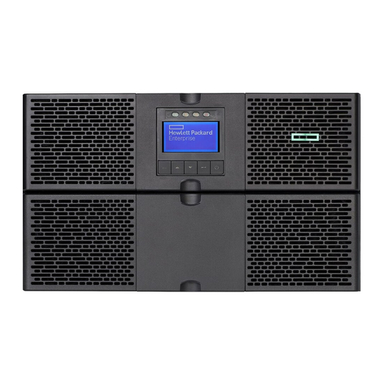
This chapter describes the external and internal server features and components. Overview The HPE G2 R8000 6U UPS features a 6U rack-mount design and offers power protection for loads up to 8000VA/7200W. To benefit from the latest product enhancements, update to the latest version of the UPS firmware and software. -
Page 6: Ups Front Panel Controls
UPS front panel controls Item Description Escape button Up button Down button Enter button Power button Front panel LEDs Component identification... -
Page 7: Rear Panel Components
Item Indicator Status Description Online mode The UPS is operating normally online or in high efficiency mode. Battery mode The UPS is on battery mode. Bypass mode The UPS is in bypass mode. Fault The UPS has an active alarm or fault. For more information, see the Troubleshooting section. -
Page 8: Erm Rear Panel Components
Item Description ERM to UPS connection ERM recognition port Remote Power Off (RPO) terminal block 1Gb UPS Network Management Module Remote On/Off (ROO) terminal block Dry contacts communications port USB communications port NOTE: This port is used for UPS firmware updates. For more information, see USB communications port. -
Page 9: Dry Contact Port
Dry contact port CAUTION: Before using the dry contact port, the following cautions must be observed: • The relay output contacts cannot be connected to any utility circuits. • Reinforced insulation to the utility is required. • The relay output contacts have a maximum rating of 250VAC/5A. The UPS has four relay outputs. -
Page 10: Roo
Description Not on battery User common On bypass Low battery Load protected On battery n.o. Contact normally open n.o. Contact normally closed ROO allows remote action of the power button to switch the UPS on and off. • When the contact changes from open to closed, the UPS is switched-on (or stays On). •... - Page 11 NOTE: Leave the RPO connector installed in the RPO port on the UPS even if the RPO function is not needed. The following images illustrate the RPO connections. Figure 4: Internal power supply Figure 5: External power supply Component identification...
-
Page 12: Installation
Installation Precautions Save these instructions. This document contains important safety instructions that must be followed during installation, operation, and maintenance of the UPS and batteries. WARNING: A risk of personal injury from electric shock and hazardous energy levels exists. The installation of options and routine maintenance and service of this product must be performed by individuals who are knowledgeable about the procedures, precautions, and hazards associated with AC power products. -
Page 13: Selecting A Site
• Screws • Washers Selecting a site WARNING: To prevent fire or electric shock, install the unit in a temperature- and humidity- controlled indoor environment, free of conductive contaminants. When selecting a site, consider the following factors: • Elevated operating ambient temperature—If the equipment is installed in a closed or multiunit rack assembly, the operating ambient temperature of the rack environment might be greater than room ambient temperature. -
Page 14: Installing The Mounting Rails
Installing the mounting rails WARNING: To reduce the risk of personal injury or damage to the equipment, be sure that: • The leveling feet are extended to the floor. • The full weight of the rack rests on the leveling feet. •... - Page 15 2. Remove four screws from the bezel, and then remove the bezel. 3. Remove three screws, and then remove the battery cover. Installation...
-
Page 16: Installing The Ups
4. Insert the battery pack, and then reinstall the battery cover and the bezel. Installing the UPS Before installing the UPS, review and observe all warnings in Precautions. WARNING: A risk of personal injury or damage to the equipment exists. Uneven loading of equipment in the rack might cause the rack to become unstable. -
Page 17: Connecting The Serial Communications Port
3. With one person on each side, lift the chassis to rail level and slide the chassis on the mounting rails. 4. Attach the chassis to the rack using the supplied screws. Connecting the serial communications port CAUTION: Use only the computer interface cable supplied with the UPS to connect the communications port to the host computer. -
Page 18: Connecting The Ground Bonding Cable
NOTE: Wire the connector block using stranded, nonshielded wire (AWG #22 - #18, or equivalent). Separate wire pairs are attached to a single, normally open contact in a parallel connection. Hewlett Packard Enterprise recommends using different colors for the positive and negative wires. If a connector becomes disconnected and is reconnected with reversed polarity, an RPO is initiated. -
Page 19: Connecting The Ups To Utility Power
Connecting the UPS to utility power WARNING: To prevent injury from electric shock or damage to the equipment: • Plug the input line cord into a grounded (earthed) electrical outlet that is installed near the equipment and is easily accessible. •... - Page 20 10mm (8AWG) 18lb in/2.03 Nm 105°C (221°F) N (L2) Neutral (phase) 16mm (6AWG) 90°C (194°F) Ground Copper wire, solid, or stranded. Connecting the Input/Output WARNING: Hewlett Packard Enterprise recommends that this connection is made only by a licensed electrician. Installation...
-
Page 21: Connecting Devices To The Ups
Prerequisites • Make sure that the upstream protection device is open. • Make sure that the ground wire is connected. Procedure 1. Remove the terminal block cover by loosening the screw. 2. Insert the AC cable through the cable gland. 3. - Page 22 Battery test There are two types of battery tests: Automated Manual—through either the front panel or the SHUT command. IMPORTANT: UPS on battery mode, LCD, LED, and dry contacts must not be active during the discharge test. Battery test conditions To perform the battery test, all the following conditions must be met.
-
Page 23: Starting Power To The Load
Manual battery full test The manual battery test is run immediately, even if the UPS is operating in ABM mode, and no test is postponed or scheduled to run in float mode. • ABM mode—the ABM cycle is stopped, the test is performed, and then the ABM cycle is restarted after the test is complete. -
Page 24: Connecting The Erm To The Ups
Connecting the ERM to the UPS Connect both ends of the split ERM cable to the ERM connectors on the UPS rear panel. To install additional ERMs, connect both ends of the split ERM cable from the next ERM into the connectors on the rear panel of the previous ERM. -
Page 25: Operations
Operations Modes of operation The UPS has four modes of operation: • Standby mode • Online mode • Battery mode • Bypass mode Standby mode • No power is available at the UPS output receptacles. • The UPS charges the batteries as necessary. The UPS can be placed in Standby mode when the UPS is in Online mode. -
Page 26: Configuring The Ups
• Extended overload • Over temperature • Output short • Hardware failure Configuring the UPS Use the UPS front panel controls to configure the UPS. IMPORTANT: The output voltage of the UPS must be set to the same nominal voltage as the facility input. -
Page 27: Verifying The Rpo Port Connection
Main menu Submenu Display information or menu function Restore factory Returns all settings to original values Reset average Clears average power usage measurement power Reset cumul. Clears cumulated power usage measurement power Dry contacts Tests dry contact relay outputs test Settings Local settings Sets product general parameters... -
Page 28: Powering Down The Ups
Powering down the UPS 1. Shut down all load devices. 2. Switch the load segment circuit breakers the OFF position. 3. Press and hold the Power button for 3 seconds. Power is removed from the load segments and the ON/OFF button blinks. Operations... -
Page 29: Power Protector
To download the latest version of HPE Power Manager software, see the Hewlett Packard Enterprise website. NOTE: Although the HPE 1GB UPS Management Module ships with the UPS, the HPE Power Protector Client is the primary software for the servers. -
Page 30: Maintenance
2. Remove the screws securing the ERM to the rack. 3. Remove the ERM from the rack. To replace the component, reverse the removal procedure. Updating the UPS firmware To update the UPS firmware, see the Hewlett Packard Enterprise website. Maintenance... -
Page 31: Troubleshooting
Troubleshooting Bypass mode Symptom LED is on. Cause • An overload or a fault has occurred. • A command has been received and the UPS is in Bypass mode. Action 1. Equipment is powered but not protected by the UPS. 2. -
Page 32: Battery Fault
Action 1. Verify that all batteries are properly connected. 2. If condition persists, contact your service representative. Battery fault Symptom LED is on, continuous beep. Cause • The battery test failed due to bad or disconnected batteries. • The battery minimum voltage is reached and the UPS is in ABM cycling mode. Action 1. -
Page 33: Ups Overtemperature
Action 1. Remove some of the equipment from the UPS 2. The UPS continues to operate, but may switch to Bypass mode or shut down if the load increases. 3. The alarm resets when the condition becomes inactive. UPS overtemperature Symptom LED is on, one beep every three seconds. -
Page 34: I/O Bad Wiring
Action If the UPS status menu displays the "Remote Power Off" notice, inactive the RPO input. I/O bad wiring Symptom I/O LED is on and there is a continuous beep. Cause I/O cables are not connected to the correct terminal blocks. Action Correctly connect the I/O cables. -
Page 35: Specifications
Specifications UPS physical specifications Parameter Value Height 25.9 (10.19in) Depth 76.2cm (30.0in) Width 43.9cm (17.3in) Weight 89.7kg (197.7lb) ERM physical specifications Parameter Value Height 13.0cm (5.1in) Depth 76.2cm (30.0in) Width 43.9cm (17.3in) Weight 63.45kg (139.88lb) UPS input specifications UPS model Utility voltage Available settings Branch circuit... -
Page 36: Voltage Specifications
Voltage specifications Configuration setting (VAC) Available nominal output voltage (VAC) G2 R8000 NA/JPN G2 R8000 INTL Output tolerance specifications Source of power Regulation Utility power Sync with line ±5% of nominal line frequency Battery power ±0.5% of auto-selected nominal frequency Output feature specifications Feature Specification... -
Page 37: Environmental Specifications
Table 2: G2 R8000 INTL battery runtimes Load % Estimated battery Runtime with one ERM Runtime with four runtime (minutes) (minutes) ERMs (minutes)* Environmental specifications Feature Specification Operating temperature 0ºC to 40ºC (32ºF to 104ºF) Nonoperating • With batteries—0ºC to 40ºC (32ºF to 104ºF) temperature •... -
Page 38: Ups Spare Parts
UPS spare parts Description Spare part number UPS battery P09830-001 P09833-001 ERM accessory kit P10252-001 UPS/ERM CTO mounting shelf with rails P10250-001 UPS spare parts... -
Page 39: Electrostatic Discharge
Electrostatic discharge Preventing electrostatic discharge To prevent damaging the system, be aware of the precautions you must follow when setting up the system or handling parts. A discharge of static electricity from a finger or other conductor may damage system boards or other static-sensitive devices. This type of damage may reduce the life expectancy of the device. -
Page 40: Websites
Websites General websites Hewlett Packard Enterprise Information Library www.hpe.com/info/EIL Single Point of Connectivity Knowledge (SPOCK) Storage compatibility matrix www.hpe.com/storage/spock Storage white papers and analyst reports www.hpe.com/storage/whitepapers For additional websites, see Support and other resources. Websites... -
Page 41: Support And Other Resources
Accessing Hewlett Packard Enterprise Support • For live assistance, go to the Contact Hewlett Packard Enterprise Worldwide website: http://www.hpe.com/assistance • To access documentation and support services, go to the Hewlett Packard Enterprise Support Center website: http://www.hpe.com/support/hpesc Information to collect •... -
Page 42: Customer Self Repair
Customer self repair Hewlett Packard Enterprise customer self repair (CSR) programs allow you to repair your product. If a CSR part needs to be replaced, it will be shipped directly to you so that you can install it at your convenience. -
Page 43: Regulatory Information
Documentation feedback Hewlett Packard Enterprise is committed to providing documentation that meets your needs. To help us improve the documentation, send any errors, suggestions, or comments to Documentation Feedback (docsfeedback@hpe.com). When submitting your feedback, include the document title, part number, edition, and publication date located on the front cover of the document.
Need help?
Do you have a question about the HPE G2 R8000 6U and is the answer not in the manual?
Questions and answers