Table of Contents
Advertisement
Up to 100metres Range
•
1 – 3 Button versions
•
12-30Vdc 0r 230Vac versions
•
Reliable FM Technology
•
Up to four 1000W Relay switches
•
Waterproof Receiver (IP68)
•
Momentary or Latching Relays
•
Any Switch Map to Any Relay
•
Output
General Purpose Remote
General Purpose Remote
General Purpose Remote
General Purpose Remote
•
Switching
Switching
Switching
Switching
Electric Gates
Electric Gates
Electric Gates
Electric Gates
•
Roller Shutter Doors
Roller Shutter Doors
Roller Shutter Doors
Roller Shutter Doors
•
Garden Lighting
Garden Lighting
Garden Lighting
Garden Lighting
•
Description
Description
Description
Description
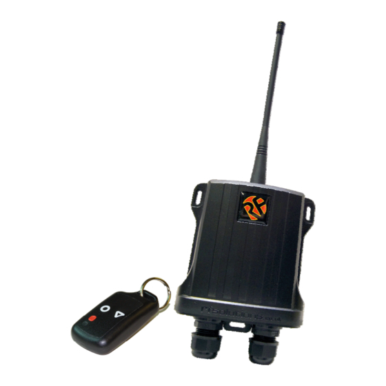
Supplied complete ready to go the HORNET is a rugged IP68 weatherproof remote
control system. Built in mounting points and easy wiring using High Quality screw
Terminals.
With a range of up to100m the HORNET is ideal for a wide variety of switching appli-
cations.
Additional transmitters may be added using the 'learn' process, any button on the
transmitter can be used to control one or many outputs of the receiver.
HORNET Remote Control Systems
HORNET Remote Control Systems
HORNET Remote Control Systems
HORNET Remote Control Systems
DS HORNET-10
Advertisement
Table of Contents

Related Manuals for RF SOLUTIONS Hornet-S2


Summary of Contents for RF SOLUTIONS Hornet-S2
- Page 1 HORNET Remote Control Systems HORNET Remote Control Systems HORNET Remote Control Systems HORNET Remote Control Systems Up to 100metres Range • 1 – 3 Button versions • 12-30Vdc 0r 230Vac versions • Reliable FM Technology • Up to four 1000W Relay switches •...
- Page 2 HORNET HORNET HORNET HORNET- - - - S1 / HORNET S1 / HORNET S1 / HORNET S1 / HORNET- - - - S2 / HORNET S2 / HORNET S2 / HORNET S2 / HORNET- - - - S3 (12 S3 (12 S3 (12 S3 (12- - - - 32Vdc Receivers) 32Vdc Receivers)
-
Page 3: Advanced Operation
Advanced Operation Advanced Operation Advanced Operation Advanced Operation To pair a new transmitter switch follow this procedure To pair a new transmitter switch follow this procedure To pair a new transmitter switch follow this procedure To pair a new transmitter switch follow this procedure Any transmitter button can be configured to operate any of the receiver relays. - Page 4 HORNET- - - - S1M / HORNET S2M (230Vac Powered Receivers) HORNET S1M / HORNET S2M (230Vac Powered Receivers) HORNET HORNET S1M / HORNET S2M (230Vac Powered Receivers) S1M / HORNET S2M (230Vac Powered Receivers) The HORNET system provides up to 4 isolated switches each capable of switching up to 6A @230V Open the enclosure by removing the two fixing screws from the base of the enclosure and the antenna, the board should then slide out.
- Page 5 Advanced Operation Advanced Operation Advanced Operation Advanced Operation Please Note: During Learn and Erase the relays operate at high speed. They should be isolated from sensi- Please Note: Please Note: Please Note: tive equipment during this process. To Pair additional Transmitter buttons to receiver Relay #1 To Pair additional Transmitter buttons to receiver Relay #1 To Pair additional Transmitter buttons to receiver Relay #1 To Pair additional Transmitter buttons to receiver Relay #1...
- Page 6 (MHz) (MHz) (Metres) (Metres) (MHz) (MHz) (Metres) (Metres) HORNET-S1 System 1 channel 433.92 HORNET-S2 System 2 channel 433.92 HORNET-S3 System 3 channel 433.92 Systems Operating at 230Vac Systems Operating at 230Vac Systems Operating at 230Vac Systems Operating at 230Vac Frequency...
-
Page 7: Low Battery Indication
Low Battery Indication Low Battery Indication Low Battery Indication Low Battery Indication When the battery on the HORNET-TX becomes low (<2.1V) the LED will indicate this by pulsing on and off and one second intervals. The battery should be changed at this point. When the battery reaches this level the HORNET-TX may continue to operate but the range will be reduced and the LED will dim. -
Page 8: Electrical Characteristics
*The relay contacts in this unit are for functional use only and must not be used for isolation purposes Waste Batteries and Accumulators Waste Batteries and Accumulators Waste Batteries and Accumulators Waste Batteries and Accumulators RF Solutions Ltd. Recycling Notice RF Solutions Ltd. Recycling Notice RF Solutions Ltd. Recycling Notice RF Solutions Ltd. Recycling Notice Directive 2006/66/EC... - Page 9 Installation diagram Installation diagram Installation diagram Installation diagram NOT TO SCALE NOT TO SCALE NOT TO SCALE NOT TO SCALE Disclaimer Disclaimer Disclaimer Disclaimer Whilst the information in this document is believed to be correct at the time of issue, R.F.Solutions Ltd does not accept any liability whatsoever for its accuracy, adequacy or completeness.
Need help?
Do you have a question about the Hornet-S2 and is the answer not in the manual?
Questions and answers