Subscribe to Our Youtube Channel
Summary of Contents for Tanda TX7211
- Page 1 TX7211 Addressable Sounder Circuit Module Installation and Operation Manual TANDA UK Technology Copyright ©2015, All right reserved.
- Page 2 TX7211 Addressable Sounder Circuit Module Installation & Operation Manual Product Safety To prevent severe injury and loss of life or propert y, read the instruction carefully before installing the module to ensure proper and safe operation of the system. European Union directive...
-
Page 3: Table Of Contents
TX7211 Addressable Sounder Circuit Module Installation & Operation Manual Table of Content 1 Introduction ............................4 1.1 Ov erview ............................. 4 1.2 Feature and Benefits ......................... 4 1.3 Technical Specification......................4 2 Installation............................5 2.1 I nstallation Preparation ......................5 2.2 I nstallation and Wiring ....................... -
Page 4: Introduction
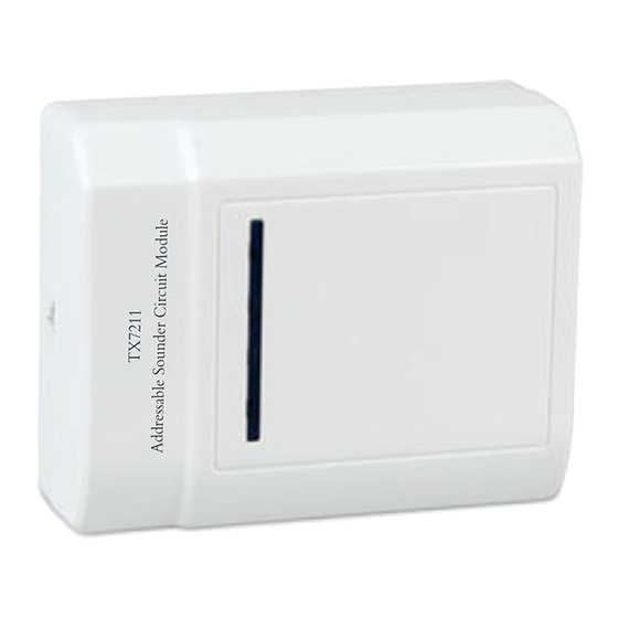
1 Introduction 1.1 Overview TX7211 Addressable Sounder Circuit Module unit is an addressabl e interface module, which will integrate conventional detectors or conventional manual call points to addressable system. When any of the connected devices alarms are active, the unit can send the alarm message to fire alarm controller, which generates alarm signal and displays its address. -
Page 5: Installation
TX7211 Addressable Sounder Circuit Module Installation & Operation Manual 2 Installation 2.1 Installation Preparation This Addressabl e Sounder Circuit Module Unit must be installed, commissioned and maintained by a qualified or factory trained service personnel. The installation must be installed in compliance with all local codes having a jurisdiction in your area or BS 5839 Part 1 and EN54. -
Page 6: Addressable Sounder Circuit Module Unit Configuration
TX7211 Addressable Sounder Circuit Module Installation & Operation Manual Terminal Description Z1 Signal In Non-polarity Z2 Signal In Non-polarity D1 External Power Supply In Non- polarity D2 External Power Supply In Non- polarity L+ Remote Indicator (+) L- Remote Indicator (-) - Page 7 TX7211 Addressable Sounder Circuit Module Installation & Operation Manual Figure 3: Programmer Connection Detail 1. Read Address: 001 Address: 001 2. Write Next Address: 002 3. R/W Config 4. Set Success Fail Figure 6 Figure 4 Figure 5 here are four working mode in the module. The module is defaulted mode I (1). Working mode (I, II, III, IV) can be set in field referring to the corresponding parameters (1, 2, 3, 4).
-
Page 8: General Maintenance
TX7211 Addressable Sounder Circuit Module Installation & Operation Manual High address: Fire alarm signal Mode III Fire alarm signal Mode IV Low address: pre-alarm signal High address: continuous alarm signal Pulse durations of pre-alarm and fire alarm are shown in Fig.7 and Fig. 8. -
Page 9: Troubleshooting Guide
TX7211 Addressable Sounder Circuit Module Installation & Operation Manual 5 Troubleshooting Guide What you notice What it means What to do The wiring is loose Conduct maintenance Address not enrolling The address is duplicate Re-Commission the device Unable to commission...


Need help?
Do you have a question about the TX7211 and is the answer not in the manual?
Questions and answers