
Related Manuals for RollSeal SC-325M

Summary of Contents for RollSeal SC-325M
- Page 1 RollSeal SC-325M & SC-650M Controllers Owners Manual RollSeal 1733 County Road 68 Bremen, Alabama 35033 256-287-7000 Manual No. 4801-5161 REV 04-2019 Owners Manual RollSeal SC-325M & SC-650M Controllers...
-
Page 2: Table Of Contents
Limited Warranty ..............................9 Ratings and Specifications ........................... 10 Introduction ................................11 How the Smart Controllers Communicate with the RollSeal Automatic Doors........11 Smart Controller User Interface ........................... 12 The Power Switch ............................. 12 Interpreting the Display Indicator ......................13 5.2.1... - Page 3 12.2 Interlocking Two Automatic Doors ......................37 12.3 Connecting the Operator OPEN/CLOSE Switch Boxes to the Smart Controller in the RollSeal Doors. COM/OPEN/CLOSE Pins shown detailed connector drawings. (RollSeal Smart Switches) ....38 12.4 Connecting the Operator OPEN/CLOSE Switch Boxes to the Smart Controller in the RollSeal Doors.
-
Page 4: Warnings (Advertisements)
Systems Or Machines. It Is The Responsibility Of The Installer To Ensure That The Drive Is Installed Safely And In Accordance With Any Regulations Which Apply To The End Product At The Place Of Use, For Example, Regarding Safety Part No 4801-5161 REV 04-2019 RollSeal SC-325M & SC-650M Controllers Page 3... - Page 5 Failure To Observe This Precaution Could Result In Severe Bodily Injury Or Death! Warning! Item 4501-6312 (Warning Moving Door Label) Supplied With Door, MUST Be Installed On Inside Of Cooler/Freezer Beside Door Opening. Part No 4801-5161 REV 04-2019 RollSeal SC-325M & SC-650M Controllers Page 4...
- Page 6 7. Install the Entrapment Warning label next to the control button in a prominent location. Install the Emergency Release Marking. Attach the marking on or next to the emergency release. Part No 4801-5161 REV 04-2019 RollSeal SC-325M & SC-650M Controllers Page 5...
- Page 7 Pl'attention articulaire doit être donnée pour les aires sectionnelles transversales de conducteurs, le choix d'elles fusées ou autre protection, et terre / prises de terre protecteur ! Part No 4801-5161 REV 04-2019 RollSeal SC-325M & SC-650M Controllers Page 6...
- Page 8 ! Avertissement! Point 4501-6312 (Avertissement Moving étiquette de porte) Livré avec porte, doit être installé à l'intérieur du réfrigérateur / congélateur côté Ouverture de la porte. Part No 4801-5161 REV 04-2019 RollSeal SC-325M & SC-650M Controllers Page 7...
- Page 9 Un improprement qui opère ou balancé porte peut causer blessure sévère ou mort. Formez les technicien de systèmes de porte faitez les réparations per les câbles, réunions de source, et autre quincaillerie. SAUVEZ CES INSTRUCTIONS. Part No 4801-5161 REV 04-2019 RollSeal SC-325M & SC-650M Controllers Page 8...
-
Page 10: Limited Warranty
This warranty gives you specific legal rights and you may also have other rights that vary from area to area. Warrantor: RollSeal 1733 County Road 68 Bremen, Al 35033 256-287-7000 Warning!! Part No 4801-5161 REV 04-2019 RollSeal SC-325M & SC-650M Controllers Page 9... -
Page 11: Ratings And Specifications
CONDENSATION MANAGEMENT SYSTEM (CMS): Voltage Rating 230 VAC ± 10% 50/60 Hz Blower 135 Watt Heater 1200 Watt Total Current: 6.0 A @ 230 VAC (Typical) 9.0 A @ 230 VAC (Max.) Part No 4801-5161 REV 04-2019 RollSeal SC-325M & SC-650M Controllers Page 10... -
Page 12: Introduction
4.1 How the Smart Controllers Communicate with the RollSeal Automatic Doors. Inside the upper right housing of the RollSeal Automatic Door is an encoder that sends electrical pulses to the Smart Controller when the door is moving and the controller is in the normal operating mode. The controllers refer to the position of the door in units of “Counts”, which is based upon the number of encoded pulses that the... -
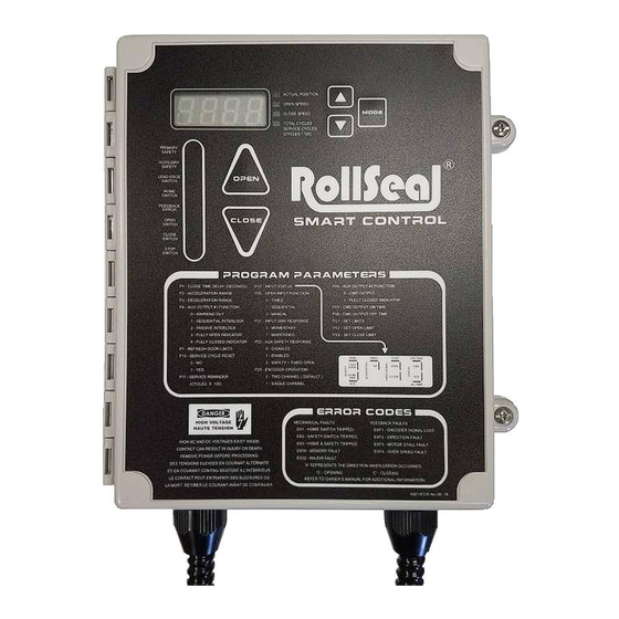
Page 13: Smart Controller User Interface
There is an LED on the Display Indicator that will light when the Safety beam is interrupted. See Section 5.2.7 for more discussion on the function of the Safety Beam. Part No 4801-5161 REV 04-2019 RollSeal SC-325M & SC-650M Controllers Page 12... -
Page 14: Interpreting The Display Indicator
When the Smart Controller is in the Jog Mode, the display will indicate “J O G” as shown at the right. See Section 7 for a description of the Jog Mode. Part No 4801-5161 REV 04-2019 RollSeal SC-325M & SC-650M Controllers Page 13... -
Page 15: Service Reminder Indication
5.2.9 Home Switch The RollSeal automatic doors contains a Home limit switch for determining the “Home” or full open position of the door. When the door is fully opened the Home limit switch is triggered to stop the door. At this position the actual reading on the Display indicator will be zero (0). -
Page 16: Sc-325M And Sc-650M Initial Setup
6. SC-325M and SC-650M Initial Setup PROGRAM PARAMETERS P1 - Close Time Delay (Seconds) P7 - Refresh Door Limits P3 - Deceleration Range P10 - Service Cycle Reset P4 – Warning Output Function 0 - No 0 – Door Movement or Door about to Close... - Page 17 4 = Door Closed Indication The Warning Output will be used to signal when the door is fully “closed” for monitoring purposes. P4 Auxiliary Relay Status (Door\ Status) Part No 4801-5161 REV 04-2019 RollSeal SC-325M & SC-650M Controllers Page 16...
- Page 18 This setting selects whether the Open and Close switch response is Momentary (0) or Maintained (1). If maintained, the switch must be held during the entire open or close cycle for the door to operate. Part No 4801-5161 REV 04-2019 RollSeal SC-325M & SC-650M Controllers Page 17...
- Page 19 Closed Limit. Use the Up ( ) and Down ( ) arrows to set the door to a new Closed Limit position. Then press Mode to exit the programming mode and return to displaying the actual position. Part No 4801-5161 REV 04-2019 RollSeal SC-325M & SC-650M Controllers Page 18...
-
Page 20: Acceleration And Deceleration Range
Depress the Mode button again (●). PS2 (Set Open Limit) will be displayed. The door will proceed to the open limit and then stop. Once the door stops, adjust open limit using the Up ( Part No 4801-5161 REV 04-2019 RollSeal SC-325M & SC-650M Controllers Page 19... -
Page 21: Jog Mode
While Completely Closes Closes at that point. Open (after Door MANUAL) Stops Door after 1-2 While OPENing Seconds While CLOSing Reopens door Stops Door (Immediately) & starts Time Delay Part No 4801-5161 REV 04-2019 RollSeal SC-325M & SC-650M Controllers Page 20... -
Page 22: Directional Switch Input
Operation is simple. Momentarily push “OPEN” to open the door, momentarily push “CLOSE” to close the door and momentarily push “STOP” to stop the door. However, the SC-325M and SC-650M controller can be programmed to perform special events with these directional switches. -
Page 23: Troubleshooting Controller And/Or Door
The “UPS Status” display segment is “ON” when the door is being powered from the battery and “OFF” when the door is being powered from AC Line power. (Future Use) Part No 4801-5161 REV 04-2019 RollSeal SC-325M & SC-650M Controllers Page 22... -
Page 24: Error Codes And Recommended Action
Signal Wires reversed. EOF3 Opening, Motor Stall Fault Motor Stall Fault ECF3 Closing, Motor Stall Fault EOF4 Opening, Over Speed Fault Over Speed Fault ECF4 Closing, Over Speed Fault Part No 4801-5161 REV 04-2019 RollSeal SC-325M & SC-650M Controllers Page 23... - Page 25 Battery is present but too low to operate door if flashing. UPS (Battery Backup): Future Feature that is not standard on all RollSeal Models UPS is engaged if the LED is illuminated. This means that the door is functioning only on battery backup.
- Page 26 ROLLSEAL SMART SWITCH Part No 4801-5161 REV 04-2019 RollSeal SC-325M & SC-650M Controllers Page 25...
-
Page 27: Controller Installation And Setup
Determine the required Powering Voltage whether 115 VAC (SC-325M only) or 230 VAC. The SC-325M Controllers are factory preset to 115 VAC and the RS-500 doors factory prewired to require a 115 VAC power supply. The SC-650M controllers are factory preset to 230 VAC and the RS-600 doors factory prewired to require a 230 VAC power supply. -
Page 28: Typical Smart Controller Installation
10.3 Connection of Controller to Head Unit. Mount controller at desired location within 3’ of the junction box on Head Unit. Controller has and AC and DC harness prewired that connects to head unit. Part No 4801-5161 REV 04-2019 RollSeal SC-325M & SC-650M Controllers Page 27... - Page 29 Side View Cooler Wall Inside Switch Front View Inside Switch Side View Cover Outside Switch Side View Outside Drill Minimum Switch Conduit 1-3/4 in Hole Front View Straps Part No 4801-5161 REV 04-2019 RollSeal SC-325M & SC-650M Controllers Page 28...
-
Page 30: Installation Of Pre-Wired Switches (Standard Two Button Switches)
Press “Open” (and “Close” if required) a couple times to insure proper operation. Press “Open” (and “Close” if required) with the Inside Switch a couple times to insure proper operation. Verify Safety Beams reverse door when blocked during closing. Part No 4801-5161 REV 04-2019 RollSeal SC-325M & SC-650M Controllers Page 29... - Page 31 Manual Crank Handle for motor is mounted outside. The door is now ready for operation. NOTE: See 4801-5162 RS500/600 Series Doors Installation Manual for more information on proper Egress System installation. Part No 4801-5161 REV 04-2019 RollSeal SC-325M & SC-650M Controllers Page 30...
-
Page 32: Smart Controller Sc-325M Connection Diagram (Internal Wiring)
11.1 Smart Controller SC-325M Layout WARNING! Ensure The Drive PCB 201 AC Selection Switch is Set Accordingly BEFORE Power Is Applied To The Controller. 11.2 Smart Controller SC-325M Connection Diagram (Internal Wiring) Part No 4801-5161 REV 04-2019 RollSeal SC-325M & SC-650M Controllers Page 31... - Page 33 11.3 Smart Controller SC-650M Layout (Factory Set to 230VAC) Part No 4801-5161 REV 04-2019 RollSeal SC-325M & SC-650M Controllers Page 32...
- Page 34 WARNING! Ensure The Drive PCB 201 AC Selection Switch is Set Accordingly BEFORE Power Is Applied To The Controller. Part No 4801-5161 REV 04-2019 RollSeal SC-325M & SC-650M Controllers Page 33...
-
Page 35: Smart Controller Sc-650M Connection Diagram (Internal Wiring)
11.4 Smart Controller SC-650M Connection Diagram (Internal Wiring) Part No 4801-5161 REV 04-2019 RollSeal SC-325M & SC-650M Controllers Page 34... -
Page 36: Smart Controller External Wiring Diagrams, Schematics, Etc
12. Smart Controller External Wiring Diagrams, Schematics, etc. 12.1 Connecting AC Power to the Smart Controller The SC-325M Controllers are factory preset to 115 VAC and the RS-500 Doors can accommodate either 115 VAC or 230 VAC power supply. The voltage selection switch must be changed accordingly. - Page 37 Dangerous High Voltages! Allow Approximately 5 Minutes For The Controller To Power-Down Before Changing Switch Settings, Jumper Placement, Or Wiring. Only a Qualified Electrician should Install or Service. Part No 4801-5161 REV 04-2019 RollSeal SC-325M & SC-650M Controllers Page 36...
-
Page 38: Interlocking Two Automatic Doors
12.2 Interlocking Two Automatic Doors Door #1 Door #2 Part No 4801-5161 REV 04-2019 RollSeal SC-325M & SC-650M Controllers Page 37... -
Page 39: Com/Open/Close Pins Shown Detailed Connector Drawings. (Rollseal Smart Switches)
12.3 Connecting the Operator OPEN/CLOSE Switch Boxes to the Smart Controller in the RollSeal Doors. COM/OPEN/CLOSE Pins shown detailed connector drawings. (RollSeal Smart Switches) Controller Board (PCB 201) OPEN/CLOSE Outside OPEN/CLOSE Inside Switch Board (PCB 202) Switch Board (PCB 202) Part No 4801-5161 REV 04-2019 RollSeal SC-325M &... -
Page 40: Connecting The Operator Open/Close Switch Boxes To The Smart Controller In The Rollseal Doors
12.4 Connecting the Operator OPEN/CLOSE Switch Boxes to the Smart Controller in the RollSeal Doors. (Standard Two Button Switches) Part No 4801-5161 REV 04-2019 RollSeal SC-325M & SC-650M Controllers Page 39... -
Page 41: Connecting Moving Door Warning Light To The Smart Controller
12.5 Connecting Moving Door Warning Light to the Smart Controller Smart Controller – Right & Left Side Compartments NOTE: Function not available when interlocking doors. Part No 4801-5161 REV 04-2019 RollSeal SC-325M & SC-650M Controllers Page 40... -
Page 42: Rollseal Automatic Door Wiring Diagram
12.6 RollSeal Automatic Door Wiring Diagram 13. Accessories 13.1 Remote Transmitter and Receiver (Ordered Separately) Depending on how the RS-500/600 is equipped, an Accessory Power Supply may be necessary for the addition of optional equipment. Accessory Power Supplies are available in 1 Amp and 4.5 Amp. -
Page 43: 2-Button Close/Open Switch Module (Ordered Separately)
The Ceiling/Wall Mount Pull Switch is normally mounted to the ceiling or near a wall to provide easy access door operation. The Ceiling Pull switch is normally wired to the PCB 201 Sequential Timed connection but may also be used for other switch operations when required. Part No 4801-5161 REV 04-2019 RollSeal SC-325M & SC-650M Controllers Page 42... -
Page 44: Connecting Switches And Bea Remote Receiver To The Smart Controller
13.4 Connecting Switches and BEA Remote Receiver to the Smart Controller Part No 4801-5161 REV 04-2019 RollSeal SC-325M & SC-650M Controllers Page 43... -
Page 45: Motion Detectors, Infrared Sensors And Loop Sensors (Ordered Separately)
Motion Detectors, Infrared Sensors and Loop Sensors are optional accessories that can improve the efficiency and performance of your RollSeal Door. Sensors can also help prevent damage to the RollSeal Door by preventing the door from closing while lifts or objects are present in the vicinity. -
Page 46: Wiring Iris Infrared And Microwave Sensor
13.5.3 Wiring IRIS Infrared and Microwave Sensor 13.5.4 Wiring Matrix 2 Loop Sensor Part No 4801-5161 REV 04-2019 RollSeal SC-325M & SC-650M Controllers Page 45... -
Page 47: Position Of The J11 And J14 Jumpers
13.5.5 Position of the J11 and J14 Jumpers 14. Replacement Parts and Optional Accessories This manual as well as the 4801-5162 RS 500M-600M NSF Door Install Manual can be obtained electronically at www.rollseal.net. 14.1 SC-325M Controller SC-325M Controls, Parts, and Accessories Part Number Description Notes Controller... -
Page 48: Sc-650M Controller
6407-6088 /PCB Brake Module DBVF vr.9598 Use with SC-650M Controllers Thermal Switch 3001-6507 SWITCH Thermal C1005B 3B101BR3 Door Assemblies 6407-0621 /DOOR ASSY SC-650M Use with SC-650M Controllers ONLY Part No 4801-5161 REV 04-2019 RollSeal SC-325M & SC-650M Controllers Page 47... -
Page 49: Door Replacement Parts And Accessories
Motion Detectors and Sensors 3595-0108 Falcon XL 3595-0103 3595-0006 Falcon EX 3595-0104 3595-0127 Falcon IS40 3595-0125 IRIS 3595-0110 Matrix2 Terminal Blocks 3006-5076 2 Position Terminal Block 3006-5077 3 Position Terminal Block Part No 4801-5161 REV 04-2019 RollSeal SC-325M & SC-650M Controllers Page 48... - Page 50 HRNS 6’ M SW CNTRL TO OUT 2 BU 1903-3122 HRNS 3’ 2-ButtonInsideCooler 1903-6119 Remote Operation 3595-0105 Remote Receiver 3595-0106 Remote Transmitter Manuals 4801-5161 RS SC-M Controls Manual 4802-5162 RS-500/600 M Install Manual Part No 4801-5161 REV 04-2019 RollSeal SC-325M & SC-650M Controllers Page 49...
- Page 51 Part No 4801-5161 REV 04-2019 RollSeal SC-325M & SC-650M Controllers Page 50...
Need help?
Do you have a question about the SC-325M and is the answer not in the manual?
Questions and answers