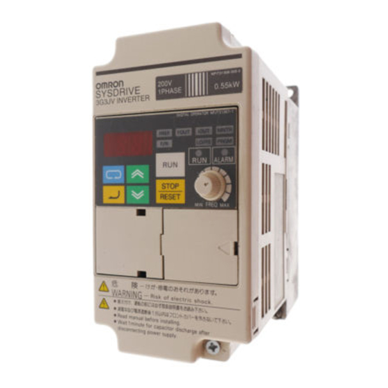
Omron 3G3JV Series Quick Start Manual
Hide thumbs
Also See for 3G3JV Series:
- User manual (246 pages) ,
- Setup manual (72 pages) ,
- Manual (49 pages)
Advertisement
Quick Links
3 G 3 J V
020 8450 4646
General telephone enquiries and technical support
020 8233 1468
Factory automation technical support
020 8450 8087
Fax number
1 Apsley Way, Staples Corner, London, NW2 7HF
q u i c k s t a r t g u i d e
020 8450 0173
24hr technical helpsheet/datasheet faxback service
oeeuk_sales@eu.omron.com
Direct e-mail address for sales enquiries
www.omron.co.uk
UK website
Advertisement

Summary of Contents for Omron 3G3JV Series
- Page 1 020 8450 4646 020 8450 0173 General telephone enquiries and technical support 24hr technical helpsheet/datasheet faxback service 020 8233 1468 oeeuk_sales@eu.omron.com Factory automation technical support Direct e-mail address for sales enquiries 020 8450 8087 www.omron.co.uk Fax number...
-
Page 2: Standard Connections
Standard Connections 3G3JV PFI Noise Filter L1í R/L1 L2í S/L2 L3í T/L3 3-phase 200 V AC single-phase 200 V AC (see note 1) Multi-function contact output Forward/Stop Multi-function input 1 (S2) Multi-function input 2 (S3) Common Multi-function input 3 (S4) Multi-function input 4 (S5) Sequence input common Analogue monitor output... -
Page 3: Control Circuit Terminals
Control Circuit Terminals Symbol Name Function Signal Level Input Forward/Stop Forward at ON/Stops at OFF Photocoupler 8 mA at 24VDC Multi-function Input 1 Set by parameter n36 (Reverse/Stop) Note: NPN is the Multi-function input 2 Set by parameter n37 default setting for (External Fault: NO) these terminals. -
Page 4: Installation
Two, 5 dia. holes Installation Dimensions Supply Recommendations Rated Model Voltage 3G3JV- MCCB (A) Wire (mm2) Single Phase AB001 200 VAC AB002 AB004 AB007 AB015 A4002 A4004 A4007 A4015 A4022 A4030 A4040 Noise Filter Specifications Model Filter 3G3JV 3G3JV AB001 PFI1010E AB002 PFI1010E... - Page 5 Indicators (Setting/Monitor Data display item indicators) Keys FREQ adjuster Appearance Name Function Data display Displays relevant data items, such as frequency reference, output frequency and parameter set values. FREQ adjuster Sets the frequency reference within a range between 0Hz and the maximum frequency. FREF indicator The frequency reference can be monitored or set while this indicator is lit.
- Page 6 Quick Start Parameter List (Refer to manual for complete list) Parameter No. Description Range Default Manual Ref. Page Parameter Access: 0 to 9 0 - Limited Parameter access 1 - Full Parameter access 8 - Factory Parameter Initialise Operation Mode Selection: 0 - Stop/Reset key or Keypad enabled 1 - Multi-function terminal input is enabled Freq.
- Page 7 Multi-function Inputs Multi-function Outputs Value Function Value Function Reverse/Stop Fault output External fault (NO) During RUN External fault (NC) Frequency agree Fault reset Overtorque being monitored (NO) Multi-step speed reference 1 RUN mode Multi-step speed reference 2 Inverter ready Multi-step speed reference 3 Undervoltage in progress Inching command Analogue Output Functions...
-
Page 8: Protective And Diagnostic Functions
Protective and Diagnostic Functions Fault Display Fault name and meaning Possible cause and remedy Overcurrent Check output for short circuit or ground fault. Output current is higher than The Load is too large, reduce it or use larger Inverter. 250% of Inverter rated current. Check motor FLA rating compared to Inverter and V/F setting.


