Table of Contents
Advertisement
Quick Links
Advertisement
Table of Contents

Related Manuals for ISKRAEMECO ME382


Summary of Contents for ISKRAEMECO ME382
- Page 1 ME382 and MT382 Technical description...
- Page 2 Iskraemeco shall not be liable for any type of damages related to this documentation or its use, or performance or non-performance of any software, hardware, service, or any third party products and services.
- Page 3 Technical description ME382 and MT382 ME382-D1 1x230 V, 5(85) A ME382-D1 1x120 V, 5(85) A ME382-D3 1x230 V, 10(100) A ME382-D3 1x120 V, 10(100) A MT382-D1 3x230/400 V, 5(85) A MT382-D2 3x230/400 V, 5(120) A MT382-D2 3x120/208 V, 5(100) A...
- Page 4 Technical description ME382 and MT382 i. About the Technical description The Technical description is intended to present the Mx382 meters (x stands for E (single-phase meters) or T (three-phase meters)). The Technical description represents the purpose of the Mx382 meters, meter construction, the way of deriving the measured quantities and meter functionalities.
- Page 5 Technical description ME382 and MT382 GMAC specialization of GCM for generating a MAC on data that is not encrypted Greenwich Mean Time Ground GPRS General Packet Radio Service Global System Mobile HDLC High-level Data Link Control Head End System Hexadecimal...
- Page 6 6 groups of digits (A-B:C.D.E*F; i.e. 0-0:1.0.0*255). In a case where the last group of digits (group F) is not written, means the value of F is 255. iii. Reference documents Installation and maintenance manual Iskraemeco’s general terms and condition – V2.20 English v/xiv INTRODUCTION...
- Page 7 SuperCap charging time was changed ME382 and MT382 object lists were updated (see chapters 12.2. Annex 2: ME382 object list and 12.3. Annex 3: MT382 object list) – new objects in the lists were added, firmware versions (core, module) were added ...
-
Page 8: Table Of Contents
3.1. Standards and references ........................9 3.2. ME382 meter description ........................11 Terminal block constituent parts – ME382-D1 (85 A) DIN connection ........12 3.2.1. Terminal block constituent parts – ME382-D3 (100 A) BS connection........12 3.2.2. Terminal block constituent parts – common for D1 (DIN) and D3 (BS) type ......13 3.2.3. - Page 9 Total energy values ......................31 3.7.10. Measurement period ......................31 METER CONSTRUCTION ........................32 4.1. Technical figures and dimensions of the ME382 meter ..............32 4.2. Technical figures and dimensions of the MT382 meter ..............35 4.3. Meter case ............................37 4.3.1.
- Page 10 Technical description ME382 and MT382 6.4.8.2. Auto answer ........................85 6.4.9. Selecting the cellular network (2G/3G) ..................88 6.5. Push ..............................89 6.5.1. Push objects..........................89 6.5.2. Data notification service ......................90 6.5.3. Push process ..........................90 6.5.4. Push related functionalities ......................91 DESCRIPTION OF MAIN METER FUNCTIONALITIES .................
- Page 11 Switching device for the MT382 meter ..................149 ANNEX ............................... 150 12.1. Annex 1: Relay, SD and M-Bus disconnect states and transitions ..........150 12.2. Annex 2: ME382 object list ......................151 12.3. Annex 3: MT382 object list ......................165 – V2.20...
- Page 12 Figure 17: Time attributes when measuring sliding demand ..................... 25 Figure 18: Overall and fixing dimensions of the ME382-D1 meter fitted with a regular terminal cover ......32 Figure 19: Overall and fixing dimensions of the ME382-D3 meter fitted with a regular terminal cover ......32 Figure 20: Overall and fixing dimensions of the ME382-D1 meter fitted with a short terminal cover .........
- Page 13 Figure 94: Neutral fault detection ............................ 133 Figure 95: Power fail example ............................134 Figure 96: Positions of the seals at ME382 meter (left) and MT382 meter (right) ............136 Figure 97: Encryption and decryption procedure ......................137 Figure 98: Three-step upgrading procedure ........................141 Figure 99: Firmware image transfer process ........................
- Page 14 Table 14: Average power ..............................30 Table 15: Total and tariff energy objects ........................... 31 Table 16: Input state control register of ME382 and MT382 meter ................... 41 Table 17: Output state control register of single-phase (ME382) meter ................42 Table 18: Output state control register of three phase (MT382) meter ................
- Page 15 Technical description ME382 and MT382 Table 57: List of events in the Power quality event log ....................104 Table 58: List of events in the Communication event log ....................105 Table 59: List of events in the M-Bus control log ......................105 Table 60: Power Failure Event Log ..........................
-
Page 16: Safety Information
Technical description ME382 and MT382 1. SAFETY INFORMATION Safety information used in this Technical description are described with the following symbols and pictograms: DANGER: for a possibly dangerous situation, which could result in severe physical injury or fatality – attention to high-risk hazards. -
Page 17: Safety Instructions
The meter installation procedure is described in the Installation and maintenance manual. For safety reasons the following instructions should be followed. See the complete Technical description for detailed technical features of ME382 and MT382 meters and its intended use. V2.20 – English 2/179 1. -
Page 18: Meter Installation Procedure
1.2.2. Meter installation procedure DANGER: The ME382/MT382 electricity meter is a device connected into the electricity network. Any unauthorized manipulation of the device is dangerous for life and prohibited according to the applicable legislation. Any attempt to damage the seals as well as any unauthorized opening of the terminal or meter cover is strictly forbidden. - Page 19 Technical description ME382 and MT382 procedures, practical experience of that work, understanding the hazards which can arise during the work and the precautions to be observed, ability to recognize at all times whether it is safe to continue working. According to the basic principles, either the nominated person in control of the electrical installation or the nominated person in control of the work activity shall ensure that specific and detailed instructions are given to the personnel carrying out the work before starting and on completion of the work.
- Page 20 Technical description ME382 and MT382 CAUTION: Do not attempt to install the meter before you have isolated the installation site from the network! DANGER: The relevant preliminary fuses must be removed before making any modifications to the installation, and kept safe until completing the work to prevent the unnoticed reinsertion.
- Page 21 Technical description ME382 and MT382 The meter is intended to be mounted at an indoor metering point, in a meter cabinet, secured against the undesired access of unauthorized persons. Only scroll push button may be accessible from the outside. Do not expose meter surface to very high temperatures even though the surface is made of non-flammable plastics to prevent fire.
-
Page 22: Meter Maintenance
Technical description ME382 and MT382 1.2.3. Meter maintenance No maintenance is required during the meter’s lifetime. The implemented metering technique, built-in components and manufacturing procedures ensure high long-term stability of meters. Therefore, no recalibration is required during entire meters lifetime. -
Page 23: Energy Metering And Mx382 Meters
Meter utilizes the DLMS communication protocol in compliance with the IEC 62056-46 standard as well as IEC 62056-21. The Mx382 meters are members of the fourth generation of Iskraemeco electronic single and three-phase meters for a deregulated market of electric power, with the following common functional properties: ... -
Page 24: Mx382 Meters Introduction
Technical description ME382 and MT382 3. Mx382 METERS INTRODUCTION 3.1. Standards and references Elektrizitätszähler in Isolierstoffgehäusen für unmittelbaren Anschluß bis 60A DIN 43857-1 Grenzstromm; Hauptmaße für Wechselstromzähler Elektrizitätszähler in Isolierstoffgehäusen für unmittelbaren Anschluß bis 60A DIN 43857-2 Grenzstromm; Hauptmaße für Drehstromzähler Elektrizitätszähler;... - Page 25 Technical description ME382 and MT382 IEC 62052-11 Electricity metering equipment (AC.): General requirements, tests and test conditions - Metering equipment IEC 62052-21 Electricity metering equipment (AC.) General requirements, tests and test conditions - Tariff and load control equipment IEC 61334-4-32...
-
Page 26: Me382 Meter Description
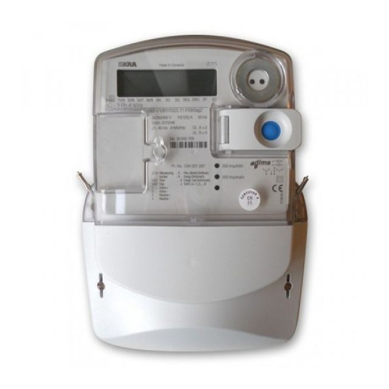
LED for active energy accuracy test LED for reactive/apparent meter cover energy sealing screw meter cover sealing screw terminal cover sealing screw terminal cover Figure 2: ME382 meter appearance – front view V2.20 – English 11/179 3. Mx382 METERS INTRODUCTION... -
Page 27: Terminal Block Constituent Parts - Me382-D1 (85 A) Din Connection
Technical description ME382 and MT382 3.2.1. Terminal block constituent parts – ME382-D1 (85 A) DIN connection meter cover sealing screw (tightening torque 0,2–0,4 N m) auxilary terminals: signal control output – 33 - left: load control output – 34, neutral – 35 - right: M-Bus –... -
Page 28: Terminal Block Constituent Parts - Common For D1 (Din) And D3 (Bs) Type
Technical description ME382 and MT382 3.2.3. Terminal block constituent parts – common for D1 (DIN) and D3 (BS) type SIM card holder external button input (50, 51) socket for P1 port terminal cover alarm input (85, 80) opening detector Figure 5: Terminal block constituent parts – common for D1 (DIN) and D3 (BS) type NOTE For detailed information, see the Installation and maintenance manual. -
Page 29: Mt382 Meter Description
Technical description ME382 and MT382 3.3. MT382 meter description IR optical liquid crystal interface display (LCD) button cover sealing door Scroll Reset buttons place for external antenna coupling device accuracy test LED for active energy accuracy test LED for reactive/... -
Page 30: Terminal Block Constituent Parts - Mt382-D1/D2
Technical description ME382 and MT382 3.3.1. Terminal block constituent parts – MT382-D1/D2 socket for switching external button input (50, 51) SIM card P1 port device holder connector alarm input (85, 80) meter cover sealing screw (0,2-0,4N m) terminal cover opening detector... -
Page 31: Terminal Block Constituent Parts - Mt382-T1
Technical description ME382 and MT382 3.3.2. Terminal block constituent parts – MT382-T1 SIM card holder external button input (50, 51) socket for P1 port alarm input (85, 80) meter cover sealing screw (0,2-0,4 N m) terminal cover fixing point terminal cover... -
Page 32: Main Meter Properties
Technical description ME382 and MT382 3.4. Main meter properties Active energy and demand meter of accuracy class 1 or 2 (according to IEC 62053-21). Reactive energy and demand meter of accuracy class 2 or 3 (according to IEC 62053-23). - Page 33 Technical description ME382 and MT382 Data menu on display (enter by pressing the Scroll button, see the Figure 48): alternate display readout mode: manual data display mode (cannot be disabled), load profile with period 1 (optional), load profile with period 2 (optional), certification data log (optional).
-
Page 34: Connection Diagram
To each connection diagram, corresponding identification number is assigned. It is generated by Iskraemeco and looks like IS 0xx.xxx, where x represents any number from 0 to 9. On the nameplate of each meter, corresponding identification number of the connection diagram is printed, and it can be found as Conn. -
Page 35: Me382-D1 Meter
Figure 9: ME38y-D1 meter connection diagram – DIN connection NOTE To connect the ME382-D1 meter into the electrical network use the connection diagram in the Figure 9. Ignore RS-485 and PLC options, because only the UMTS (3G) or GSM/GPRS communication interface is presented in the ME382-D1 meter. For more information, see the introduction in the chapter 3.5. -
Page 36: Mt382 Meter
Technical description ME382 and MT382 3.5.3. MT382 meter passive external signal load alarm control control button external input input output output M-Bus Figure 11: MT38y meter connection diagram – direct connection (left), transformer connection (right) NOTE The connection diagram presented in the Figure 11 is intended for: ... -
Page 37: Energy And Demand Registration
Technical description ME382 and MT382 3.6. Energy and demand registration The meter measures and records electric energy/power in: single-phase two wire network; three-phase four-wire network (MT382 meter only): positive and negative active energy and power (A+, A-), per phase, sum of all phases;... -
Page 38: Demand
Technical description ME382 and MT382 The meter records different types of energy (active, reactive, apparent) for all phases in one or more tariffs and stores these values in various registers according to energy direction and active tariff. Active Energy delta registers (total and tariffs) contains active energy flow within billing period in the following objects: ... -
Page 39: Figure 15: Attributes In The Case Of Block Demand (1 Period)
Technical description ME382 and MT382 Demand can be measured in the Mx382 meter according to: block demand method or sliding demand method. Block demand method At block demand method, the first time period (block) begins at the time when measurement period starts and lasts the time Td. -
Page 40: Other Demand Registers
Technical description ME382 and MT382 At the block demand method, only one average demand is calculated in one time period, while at sliding demand N average values are calculated. In this way, the measurement at sliding demand method is much more accurate. -
Page 41: Measurement Platform
Table 6: Measuring configuration type One (in the ME382 meter) or three (in the MT382 meter) metering elements can be built in the meter. The current sensor for MT382 meters is Rogowsky coil (a current transformer with an air core) and shunt for ME382 meter, while voltage sensor is a resistive voltage divider. -
Page 42: Rogowski Coil
Technical description ME382 and MT382 3.7.1.1. Rogowski coil Rogowsky coil does not contain magnetic material that could be saturated by an external magnet; consequently, the meter’s accuracy cannot be affected by an external DC (Direct Current) or AC (Alternating Current) magnetic field. -
Page 43: Measured Quantities
Technical description ME382 and MT382 NOTE Voltage Numerator and Voltage Denominator are set to 1 (default). NOTE Due to maximum count value (rollover, see the chapter 5.1. LCD), the primary current (nominator) can be max. 300 A. 3.7.3. Measured quantities Quantities that can be measured by Mx382 meter are: ... -
Page 44: Voltage
Technical description ME382 and MT382 3.7.4. Voltage 3.7.4.1. Instantaneous voltage Instantaneous voltage is measured in the meter every 100 ms per each phase with the Instantaneous voltage objects (1-0:32.7.0 for L1, 1-0:52.7.0 for L2 and 1-0:72.7.0 for L3). 3.7.4.2. Daily peak and minimum values Daily peak voltage (current) 0-0:128.8.10... -
Page 45: Current
Technical description ME382 and MT382 3.7.5. Current 3.7.5.1. Instantaneous current Instantaneous current is measured in the meter every 100 ms per each phase with the Instantaneous current objects (1-0:31.7.0 for L1, 1-0:51.7.0 for L2 and 1-0:71.7.0 for L3). Sum of all phases is also measured, with the 1-0:90.7.0 object. -
Page 46: Energy
Technical description ME382 and MT382 3.7.9. Energy 3.7.9.1. Total energy values Total SUM Total tariff 1-0:1.8.0 1-0:1.8.e 1-0:2.8.0 1-0:2.8.e 1-0:3.8.0 1-0:3.8.e 1-0:4.8.0 1-0:4.8.e 1-0:5.8.0 1-0:5.8.e 1-0:6.8.0 1-0:6.8.e QIII 1-0:7.8.0 1-0:7.8.e 1-0:8.8.0 1-0:8.8.e 1-0:9.8.0 1-0:9.8.e 1-0:10.8.0 1-0:10.8.e 1-0:15.8.0 1-0:15.8.e 1-0:16.8.0 1-0:16.8.e <e>... -
Page 47: Meter Construction
4.1. Technical figures and dimensions of the ME382 meter Figure 18: Overall and fixing dimensions of the ME382-D1 meter fitted with a regular terminal cover Figure 19: Overall and fixing dimensions of the ME382-D3 meter fitted with a regular terminal cover V2.20 –... -
Page 48: Figure 20: Overall And Fixing Dimensions Of The Me382-D1 Meter Fitted With A Short Terminal Cover
Technical description ME382 and MT382 Figure 20: Overall and fixing dimensions of the ME382-D1 meter fitted with a short terminal cover Figure 21: Overall and fixing dimensions of the ME382-D3 meter fitted with a short terminal cover V2.20 – English 33/179 4. -
Page 49: Figure 22: Overall And Fixing Dimensions Of The Me382-D1 Meter Fitted With A P1+M-Bus Terminal Cover
Technical description ME382 and MT382 Figure 22: Overall and fixing dimensions of the ME382-D1 meter fitted with a P1+M-Bus terminal cover Figure 23: Overall and fixing dimensions of the ME382-D3 meter fitted with a P1+M-Bus terminal cover V2.20 – English 34/179 4. -
Page 50: Technical Figures And Dimensions Of The Mt382 Meter
Technical description ME382 and MT382 4.2. Technical figures and dimensions of the MT382 meter Figure 24: Overall and fixing dimensions of an MT382 meter fitted with a regular terminal cover Figure 25: Overall and fixing dimensions of an MT382 meter fitted with a short terminal cover V2.20 –... -
Page 51: Figure 26: Overall And Fixing Dimensions Of The Mt382 Meter Fitted With An External Sd Terminal Cover
Technical description ME382 and MT382 Figure 26: Overall and fixing dimensions of the MT382 meter fitted with an external SD terminal cover V2.20 – English 36/179 4. METER CONSTRUCTION... -
Page 52: Meter Case
Each meter can be fixed with three screws (two lower and one upper fixing holes). The upper fixing hole is placed 115 mm (version D1) or 107 mm (version D3) at ME382 meter and 136 mm at MT382 meter above the line connecting the bottom fixing holes (DIN 43857). -
Page 53: Terminal Block
4.3.1. Terminal block A terminal block (see the Figure 3 for ME382 meter and the Figure 7 / the Figure 8 for MT382 meter) complies with the DIN 43857 standard, while the terminal block for BS connected meters (see the Figure 4) complies with the BS 7856 standard. -
Page 54: Inputs And Outputs
Technical description ME382 and MT382 Figure 28: Sliding U-I link (left: position down; right: position up) 4.3.1.2. Inputs and outputs Every meter has built-in input and output terminals. They are driven through the meter firmware functionality and can have different shared functions on the same pin through the specific configuration. Some functions (for hardware reasons) are not available on all meters. -
Page 55: Figure 30: Signal Control Terminal
Technical description ME382 and MT382 Load control power on delay defines delay time, before it is switched on when power returns. Delay time is set in seconds. It is used for grid power balance, when power returns. The meter enables that the Load control of each meter in the system switches on at different time inside a configured period of time. -
Page 56: Output For Active Switching Device
50/51 0x0080 ALARM IN 85/80 8-12 unused 0x2000 SCROLL BUTTON Button pressed 0x4000 RESET BUTTON Button pressed 0x8000 PARAM LOCK SWITCH Locked Table 16: Input state control register of ME382 and MT382 meter V2.20 – English 41/179 4. METER CONSTRUCTION... -
Page 57: Meter Cover
Technical description ME382 and MT382 Output control status register (0-0:96.3.2) of single-phase (ME382) meter is shown in the Table 17. HEX (when bit set) Bit name Remarks 0x0001 RELAY OUTPUT Relay ON 0x0002 RELAY OUTPUT Relay OFF unused 0x0010 BREAKER OUTPUT... -
Page 58: Figure 34: External Sd Terminal Cover For The Meter With Sd Unit (Left) And P1+M-Bus+Sd Terminal Cover (Right)
Technical description ME382 and MT382 Figure 34: External SD terminal cover for the meter with SD unit (left) and P1+M-Bus+SD terminal cover (right) Figure 35: P1+M-Bus terminal cover (left: with the sealable lid; right: without the sealable lid) Figure 36: Meter connection diagram on the inner side of the terminal cover V2.20 –... -
Page 59: Name Plate
ME382 and MT382 4.4. Name plate Basic data and type designation of the meter can be found on a name plate (see the Figure 37 for the ME382 meter and the Figure 38 for the MT382 meter). country of origin... -
Page 60: Figure 38: Name Plate Of The Mt382 Meter
Technical description ME382 and MT382 country of origin year of meter manufacture connection type reference frequency meter type designation transition, reference and reference max. current voltage meter serial connection number and diagrame bar code code CE mark, year of approval and... -
Page 61: Mx382 Meter Type Designation
Technical description ME382 and MT382 4.5. Mx382 meter type designation ME382-D3A42R52S63-V12V13P1B11L11-M2K0agnZ-Hxx MT382-D1A42R52S63-V12V13P0B11L11-M2K0agnZ-Hxx single-phase electronic system meter three-phase electronic system meter meter w ith GSM/GPRS communication terminal block: Imax = 85 A terminal block: Imax = 120 A terminal block: Imax = 100 A; BS type terminal block up to 6 A;... -
Page 62: Console
Technical description ME382 and MT382 5. CONSOLE Main features on the meter’s console are LCD, two LEDs and two buttons. Every meter has them integrated. 5.1. LCD The seven-segment liquid crystal display (LCD) with its description is shown in the Figure 39. -
Page 63: Figure 40: Displaying Value With Format "60
Technical description ME382 and MT382 Cursors: on the front plate below the LCD display meter has laser printed markings that belong to the cursors on the LCD. The cursor shows the state of certain function that they represent e.g. tariff, registration, switching device status and meter fault (see the Table 20). -
Page 64: Display Configuration
Technical description ME382 and MT382 Then the value in the corresponding register goes to 1000000.00, so the correct value of the register is not lost, but is out of the scope of the LCD display. Maximum limit of the internal register is 999999999. -
Page 65: Metrological Leds
ME382 right LED indicates active energy flow, left LED indicates reactive or apparent energy flow. Figure 43: LEDs at the ME382 meter MT382 upper LED indicates active energy flow, middle LED indicates reactive or apparent energy flow, ... -
Page 66: Buttons
Technical description ME382 and MT382 5.3. Buttons There are two buttons on every meter’s front side: button – the blue button that is always accessible. Its primary function is to scroll data from Scroll the Manual scroll sequence on the LCD. -
Page 67: Reduced Console Menu Type
Technical description ME382 and MT382 Scroll button is sensitive to press duration; therefore, the action is depended on release time. Reset button is not sensitive to press duration in general; therefore, the release time has no influence on its functioning. -
Page 68: General Display Readout Mode
Technical description ME382 and MT382 Menu navigation When the Reduced Console menu type is active, the user interface has only two modes (see the Figure 46): General display readout mode (Auto scroll) and Alternate display readout mode (Manual scroll). -
Page 69: Normal Console Menu Type
Technical description ME382 and MT382 In Normal console menu type Alternate display readout mode is accessible from the Data menu. When the Scroll button is first pressed, display test mode appears. By next short press on the Scroll button Std dAtA appears. Long press (> 2 s) on Scroll button when Std dAtA is on. -
Page 70: Figure 47: Entering The Data/Set Menu
Technical description ME382 and MT382 Menu navigation When the Normal Console menu type is active, the user interface has two menus that are accessed from the Display test state. The Display test state is entered from the General display readout mode by a short... -
Page 71: Data Menu
Technical description ME382 and MT382 5.3.2.1. Data menu Data menu is accessed from the Display test state by a short press on Scroll button. There are several items supported for presentation in Data menu on display. The first item is Alternate display readout mode (Std dAtA). -
Page 72: Table 28: Register Reading Procedure On The Lcd When The Reduced Console Menu Type Is Set
Technical description ME382 and MT382 Example QUESTION: How to read the Active firmware version and Active firmware core signature value on the LCD? ANSWER: Follow the steps described in the Table 28 or Table 29; choose the suitable one. NOTE If the Console menu type in the Display configuration object (0-0:196.1.3) is set as:... -
Page 73: Figure 50: Load Profile On Display Navigation
Technical description ME382 and MT382 NOTE The displayed items listed in General display readout mode (Auto scroll mode) or Alternate display readout mode (Manual scroll mode) sequence list is defined in objects General display readout (0-0:21.0.1) and Alternate display readout (0-0:21.0.2). -
Page 74: Set Menu
Technical description ME382 and MT382 Certification data log (P.99) on display Presentation of Certification data log on display is optional in Normal Console menu type. It can be enabled by a bit–parameter in the Display configuration (0-0:196.1.3). Certification data log presentation is... -
Page 75: Figure 52: Set Menu Navigation
Technical description ME382 and MT382 rESEt Meter Reset Escape into General display readout mode Enter the Lcd tESt Lcd test mode Figure 52: Set menu navigation Reset mode NOTE Meter is locked (by the parameter protection button) and sealed (buttons and covers), therefore cannot be reset unless seals are broken and parameter protection button unlocked. -
Page 76: Previous Values On A Display
Technical description ME382 and MT382 NOTE For the proper functioning of the LCD test mode in the Display configuration (0-0:196.1.3) object Console menu type should be set to Normal. 5.3.3. Previous values on a display Previous values are values of billing registers that have been captured on billing reset and stored in the billing profile –... -
Page 77: Communication
Technical description ME382 and MT382 6. COMMUNICATION 6.1. Optical interface Optical interface operates according to: IEC 62056-21 standard: Electricity metering: Data exchange for meter reading, tariff and load control, Part 21: Direct local data exchange (for remote data exchange see other standards of the IEC 62056 series) ... -
Page 78: P1 Interface
Technical description ME382 and MT382 Important instances in the meter for IEC HDLC (High-level Data Link Control) setup are: the communication speed, window size transmit/receive, maximum length of the transmitted or received information, inter octet and inactivity timeouts, ... -
Page 79: P1 Functionality
Technical description ME382 and MT382 P1 port connector is RJ11, where standard RJ11 plug can be inserted. Connector is not accessible at all times because it is protected by a sealed cover, unless if terminal cover with external M-Bus terminals and external P1 port connector is installed (optional, see the Figure 35). -
Page 80: P1 Parameters
Technical description ME382 and MT382 DLMS With IEC 62056-46 (DLMS UA) communication type, the meter sends data using the Consumer Information Push (CIP) functionality: Push setup – Consumer Information (0-6:25.9.0), Push script table (0-0:10.0.108), Push action scheduler – Consumer Information (0-4:15.0.4), ... - Page 81 Technical description ME382 and MT382 Also wireless M-Bus devices with dongle can be connected to the M-Bus interface of the meter. Both wired and wireless M-Bus devices can be connected to the meter at the same time. The meter allows the physical connection of maximum four M-Bus devices at the same time.
-
Page 82: Table 31: M-Bus Profile Status Registers Notifications
Technical description ME382 and MT382 Figure 59: Example for channel M-Bus identification numbers Device ID1 is M-Bus equipment identifier. There are four objects, one per channel. M-Bus equipment identifier is one of the parameters, which define uniqueness of the device. For successful reading of this identifier M-Bus device data must be unencrypted or successfully decrypted (the proper encryption key must be previously uploaded to E-meter and M-Bus device). - Page 83 Technical description ME382 and MT382 M-Bus event log M-Bus event log contains errors and alarms related to M-Bus devices (e.g. changes of the clock, communication errors, fraud attempt, etc). The buffer must be filled monotonously, i.e. no irregular entries are allowed. M-Bus Event log structure consists of Timestamp and Event code.
-
Page 84: Gsm/Gprs/Umts Communication Module
Technical description ME382 and MT382 M-Bus alarms There are four different groups of alarms used for M-Bus events, which are directly related to devices, connected to the E-meter. Each group consists of four different alarms, one per channel (see the Table 32). -
Page 85: Gsm/Gprs Network Diagnostic
Technical description ME382 and MT382 Initialization string The initialization string contains all necessary initialization commands to be sent to the modem in order to configure it properly. If the array contains of more than one initialization string element, requests are sent in a sequence with a defined delay time (set in ms), to allow the modem to execute the request. -
Page 86: Csd Data Connection (Gsm)
Technical description ME382 and MT382 If SIM (Subscriber Identity Module) card is not inserted in the modem, it can report value 99, especially on 3G modem. This value is consequently transferred in the GSM signal quality object. GSM status (0-0:128.20.1) object contains bit organized information about modem operation (see the Table 35). -
Page 87: Packet Data Connection (Gprs)
Technical description ME382 and MT382 Figure 60: State transitions during a successful call establishment procedure 6.4.4. Packet data connection (GPRS) The meter supports communication through GPRS mobile networks. In order to be visible within a GPRS network, the meters must establish connection to GPRS network first. Using special connection management functionality, meter can either be always connected to the GPRS network or connected only on request. - Page 88 Technical description ME382 and MT382 IPCP options Not used by the meter. PPP authentication Contains the parameters required by the PPP authentication procedure used. PPP authentication must be configured with appropriate PAP username and password, which will be accepted by the network when PDP activation request is sent.
-
Page 89: Short Message Service (Sms)
Technical description ME382 and MT382 6.4.5. Short message service (SMS) SMS message in the Mx382 meter can be used for meter wake-up request and push data. SMS message can be up to 160 characters long, where each character is 7 bits long according to the 7-bit default alphabet. -
Page 90: Sms Application Protocol Data Unit (Apdu)
Technical description ME382 and MT382 The Table 37 shows example of phone number 040123456 (national format) or +38640123456 (international format) from which it is allowed to receive SMS. To support both national and international phone number format, it is advised to use wildcard (*) instead of explicit phone number (*40123456 instead of 040123456 or +38640123456). -
Page 91: Outgoing Sms
Technical description ME382 and MT382 Figure 63: IDIS client and server model 6.4.5.3. Outgoing SMS Sending SMS is triggered by the executing Push setup methods (see the Table 38). Push setup Logical name 1. Push setup – On connectivity 0-0:25.9.0 2. -
Page 92: Incoming Sms
Technical description ME382 and MT382 Service Centre Address (SCA) used for SMS sending (SMS-SUBMIT) should be set prior executing the method. Data Coding Scheme (DCS) is always set to 8-bit data coding in the User Data. DCS Settings Meter HES... -
Page 93: Sms Wake-Up Request (Empty Incoming Sms)
Technical description ME382 and MT382 SMS Short Header 0x00 Instance ID 0-0:96.13.0 0x60 (Consumer message text – Consumer 0x0D information) 0x00 0xFF 0x02 Attribute ID 0x00 AccessSelection 0x09 0x06 0x61 0x62 COSEM data: abcdef 0x63 0x64 0x65 0x66 Table 41: Example of SMS PDU for setting object 0-0:96.13.0 6.4.5.5. -
Page 94: Modem Reset
Technical description ME382 and MT382 6.4.6. Modem reset Once GSM/GPRS communication modem is running, network specific errors or broken connections can cause modem to become unresponsive to subsequent communication attempts. Modem reset mechanism enables automatic restart and re-initialization of GSM/GPRS communication module, thus restoring it back to the fully operational mode. -
Page 95: Table 43: Modem Reset Triggers
Technical description ME382 and MT382 The Table 43 explains how errors in various stages of modem operation lead to possible modem reset. Stage Error result Initialization service first AT command sent no/invalid response MUX* start-up MUX not started Additional AT commands sent... - Page 96 Technical description ME382 and MT382 Figure 64: State diagram during modem restart procedure The entire modem reset procedure takes approximately 3 to 4 minutes to complete. Whether or not a modem reset procedure is currently in progress it can be observed using the GSM status (0-0:128.20.1) object.
-
Page 97: Tcp/Ip Based Cosem Communication Profile
Technical description ME382 and MT382 6.4.7. TCP/IP based COSEM communication profile This profile is implemented to be used in conjunction with a GPRS communication interface. Figure 65: TCP/IP based COSEM communication profiles COSEM Wrapper COSEM Wrapper protocol is a part of COSEM specification used for COSEM communication over IP networks. -
Page 98: Table 44: Cosem Wrapper Header Information
Technical description ME382 and MT382 Header information Description This 16 bit long unsigned integer value carries the version number identifying the version of the wrapper. Its value is controlled by the DLMS User Association. The Version current value is 0x0001. -
Page 99: Gsm/Gprs Connection Management
Technical description ME382 and MT382 6.4.8. GSM/GPRS connection management GSM/GPRS connection management functionality is achieved through the implementation of two COSEM classes: Auto Connect, Auto Answer. 6.4.8.1. Auto connect The meter implements Auto connect (0-0:2.1.0) object in order to be able to control the operation of auto connect functionality. -
Page 100: Auto Answer
Technical description ME382 and MT382 Value Mode description 0…99 Reserved. Always on: the device is permanently connected to the communication Network. Always on within the validity time of the calling window: the device is disconnected from the communication network outside the calling window. No connection possible outside the calling window. -
Page 101: Table 46: Modem Working Mode
Technical description ME382 and MT382 Value Mode description Line dedicated to the device. Shared line management with a limited number of calls allowed. Once the number of calls is reached, the window status becomes inactive until the next start date, whatever the result of the call. -
Page 102: Table 48: Gsm Status Object Bits B1 And B11 Relation States And Meaning
Technical description ME382 and MT382 Because the implemented GSM/GPRS communication module is a class B modem (communication over GPRS and CSD at the same time is not possible), any incoming CSD call is rejected if there is any TCP session (over GPRS) active. -
Page 103: Selecting The Cellular Network (2G/3G)
Technical description ME382 and MT382 6.4.9. Selecting the cellular network (2G/3G) For the 3G modem (Sierra Wireless SL8082) user can select the cellular network (Wireless Data Service) to operate with the Mobile Terminal/Terminal Adaptor. This can be done with the Sierra Wireless proprietary command +WWSM. -
Page 104: Push
Technical description ME382 and MT382 6.5. Push Generally, communications runs from the central system (client) to the meter (server). On the contrary, in Push operation communication runs from the meter (server) to the central system (client), where the meter initiates the communication and pushes information to the central system without any request. -
Page 105: Data Notification Service
Technical description ME382 and MT382 6.5.2. Data notification service Data_notification to the Consumer Information Interface can be pushed: periodically with triggering push operation by the meter’s Push action scheduler – Consumer information. It is optional and is used to periodically invoke of Push script table (0-0:10.0.108) with predefined selector to trigger push method on object Push setup - Consumer Information. -
Page 106: Push Related Functionalities
Technical description ME382 and MT382 6.5.4. Push related functionalities Security setup (0-0:43.0.0) object is used to secure data_notification when pushing data using pre-established association. The Management Client association and the Pre-established Client association share the same security context. Therefore, there is only one security setup object through which this security context is configured. -
Page 107: Description Of Main Meter Functionalities
Technical description ME382 and MT382 7. DESCRIPTION OF MAIN METER FUNCTIONALITIES 7.1. Measurements Beside energy and power measurement and registration and instantaneous values measurement and registration (power, voltage, current, power factor, frequency) the following meter functions are available: power quality measurements (partly according to EN 50160*), ... -
Page 108: Table 50: Profile Status Register
Technical description ME382 and MT382 Data in a load-profile recorder are accompanied with a timestamp and with the meter status in the last saving period as well as with a check sum. The timestamp indicates the end of a registration period. -
Page 109: Load Profile Options
Technical description ME382 and MT382 7.3.1. Load profiles options Access rights for Profile Generic class objects Load Profile 1, Load Profile 2, Data of Billing period 1 and Data of Billing Period 2 can be modified in runtime with dedicated parameter in Profile access options (0-0:128.90.0) object. -
Page 110: Billing Profile
Technical description ME382 and MT382 NOTE If more than one execution time is set on the same time/date, then only one billing execution will be registered in the event log and billing counter. 7.4.1. Billing profile Billing profile is the storage for billing data, captured by execution of billing actions. Billing profile buffer is organized as an array of entries. -
Page 111: Prepayment
Technical description ME382 and MT382 NOTE Billing profile is erased when attribute capture objects or capture period are set. 7.5. Prepayment Prepayment functionality allows consumption of up to a remotely preset amount of energy or credits paid in advance. Once no more credits are available, the meter will eventually disconnect the customer from the grid. - Page 112 Technical description ME382 and MT382 Figure 70: Credit transfer data structure The meter processes the received token protocol data unit through the phases (see the Figure 71). Figure 71: Token protocol data unit processing phases In the confidentiality phase, the meter decrypts the message by using appropriate encryption/decryption algorithm selected for communication over specific communication interface.
- Page 113 Technical description ME382 and MT382 Prepayment accounting The implementation of prepayment accounting functions can be separated on credit and charge functions. The credit functions include: token credit function, emergency credit function. Two types of charge functions are implemented: ...
-
Page 114: Event Logs
Technical description ME382 and MT382 7.6. Event logs Basic principle is shown in a diagram in the Figure 72. Figure 72: Event handling Events are generated by the meter itself or by its environment. All these events are logged in several event logs. -
Page 115: Standard Event Log
Technical description ME382 and MT382 The meter features the following event log objects (see the Table 52). Event log object Logical name Capacity Captured objects 0-0:1.0.0 Standard event log 0-0:99.98.0 0-0:96.11.0 0-0:1.0.0 Fraud detection log 0-0:99.98.1 0-0:96.11.1 0-0:1.0.0 Disconnector control log 0-0:99.98.2... -
Page 116: Fraud Detection Log
Technical description ME382 and MT382 IDIS event Event name Event description code RAM error Indicates a physical or a logical error in the RAM (Random Access Memory) NV memory error Indicates a physical or a logical error in the non-volatile memory Watchdog error Indicates a watch dog reset or a hardware reset of the microcontroller. -
Page 117: Disconnector Control Log
Technical description ME382 and MT382 IDIS event Event name Event description code Terminal cover removed Indicates that the terminal cover has been removed Strong DC field detected Indicates that a strong magnetic DC field has been detected. No strong DC field anymore Indicates that the strong magnetic DC field has disappeared. -
Page 118: M-Bus Event Log
Technical description ME382 and MT382 7.6.4. M-Bus event log M-Bus event log (0-0:99.98.3) contains errors and alarms related to M-Bus devices (e.g. changes of the clock, communication errors, fraud attempt, etc). The buffer must be filled monotonously, i.e. no irregular entries are allowed. -
Page 119: Power Quality Log
Technical description ME382 and MT382 7.6.5. Power quality log Power quality log object (0-0:99.98.4) contains all events related to power quality. Power quality event log structure consists of timestamp and event code. The Event object – Power quality log object (0-0:96.11.4) holds the code from the last event triggered. -
Page 120: M-Bus Master Control Logs
Technical description ME382 and MT382 IDIS Event name Event description event code PDP context established PDP context is established PDP context destroyed PDP context is destroyed PDP context failure No valid PDP context(s) retrieved Modem SW reset Modem software restart... -
Page 121: Power Failure Event Log
Technical description ME382 and MT382 7.6.8. Power failure event log Power failure event log (1-0:99.97.0) contains all events related to long power outages, i.e. start and end of a long power outage. Attributes Data type Class ID Code Access Min. -
Page 122: Alarms
Technical description ME382 and MT382 Capture to this log is done when one of the critical measurement parameters changes. In this case, all the needed information (logical name, old value and new value) are stored in dedicated objects first and then captured into certification data log. -
Page 123: Table 65: Alarm 1 Codes
Technical description ME382 and MT382 Each bit in the alarm register represents a different alarm. If any bit is set, corresponding alarm was recorded. Value of the alarm register is a 32-bit value of all active and inactive alarms. Depending on the capabilities of the HES and the utility policy, it is possible to mask unwanted alarms through the alarm filter. -
Page 124: Rtc Backup
Technical description ME382 and MT382 Alarm Description Voltage Phase Resume L2 Set when the mains voltage on L2 is in normal limits again. Voltage Phase Resume L3 Set when the mains voltage on L3 is in normal limits again. Missing Neutral Set when the neutral connection from the supplier to the meter is interrupted. -
Page 125: Time Management
Technical description ME382 and MT382 NOTE When the battery is not implemented in the meter (SuperCap use), this object shows 0 value. NOTE Data referred to the SuperCap and the Lithium battery is valid for the ambient temperature 25 °C. -
Page 126: Errors
Technical description ME382 and MT382 7.9. Errors The meter uses its automatic supervision mechanism to detect and log different types of events related to meter operation. These events can be a part of meter's internal functionality or can occur due to changes in the meter's environment. -
Page 127: Error Filter
Technical description ME382 and MT382 RTC error RTC error detected. 20-21 Unused Communication error Communication error detected. Display error Display error detected. Battery discharged Clock battery or backup capacitor is discharged. Invalid time Clock is invalid. 26-31 Unused Table 68: IE error codes register 7.9.1. -
Page 128: Activity Calendar And Tou Registration
Technical description ME382 and MT382 Measurement system error Checking of undisturbed operation and accuracy of the meter, to certain extend, performs a meter by itself. If any error is detected, meter reports it by setting Measurement System Error flag (Measurement system error). -
Page 129: Activity Calendar
Technical description ME382 and MT382 7.10.1. Activity calendar Activity calendar is time of use (TOU) object for tariff control. It allows modelling and handling of various tariff structures in the meter. It is used to store energy and demand according to tariff rate schedule. Scheduled actions are defined inside the meter. -
Page 130: Tariff Synchronization
Technical description ME382 and MT382 7.10.3. Tariff synchronization Tariff changeover in the meter can be synchronized with measurement period or not. If not, the tariff change is asynchronous by the internal tariffication scheme via activity calendar. If tariff switching must be synchronous with the measuring period, activity calendar must be set up in such a way that this is achieved. -
Page 131: Switching Device Type Designation
At transformer connected MT382 meters the relay can be configured as a disconnector functionality, which can drive external transformer switching device (option 4). ME382 meters have built-in switching device. Figure 77: Example of switching device for MT382 (left: top view; right: front view) -
Page 132: Disconnect Control
Technical description ME382 and MT382 Figure 78: MT382 meter with switching device Disconnect and reconnect can be requested: remotely via communication channel (remote disconnect, remote reconnect), manually using a Scroll button (manual disconnect, manual reconnect) or locally by a function of the meter such as limiter, register monitor or prepayment (local disconnect, local reconnect). -
Page 133: Manual Option
Technical description ME382 and MT382 7.11.2.1. Manual option 7.11.2.1.1. Manual reconnection When the meter is disconnected (state Ready_for_reconnection), the ConnEct notice is permanently displayed on display (see the Figure 79). Manual reconnection of switching device is enabled in all modes of Disconnect control object (0-0:96.3.10). -
Page 134: Manual Disconnection
Technical description ME382 and MT382 7.11.2.1.2. Manual disconnection To perform manual disconnection of the switching device (in the Disconnect control object 0-0:96.3.10 Control mode should be set to: 1, 2, 5): 1. press the Scroll button for 10 seconds until dISconn appears on the display (see the following NOTE and the Figure 82), 2. -
Page 135: By The External Button
Technical description ME382 and MT382 7.11.2.1.3. By the external button Meter is also supported with a non-potential external button. For manual reconnection of the meter, which is placed in the meter cabinet, the non-potential external button on the door of the cabinet can be used for: ... -
Page 136: Limitation
Emergency limit activation duration td - Min. over treshold duration Emergency activation Figure 84: Limiter diagram IDIS defines only one limiter object instance. Iskraemeco meters have two limiter instances, Limiter 1 object (0-0:17.0.0) and Limiter 2 object (0-0:17.0.1). V2.20 – English 121/179... -
Page 137: Advanced Power Limitation
Technical description ME382 and MT382 Actions defines the script to be executed when the monitored value crosses the threshold for minimal duration time: Action over threshold defines the action when the value of the attribute monitored crosses the threshold in upwards direction and remains over threshold for minimal over threshold duration time (Disconector script table objects 0-0:10.0.106, 1;... -
Page 138: Supervision Monitor - Idis
Technical description ME382 and MT382 NOTE The Available power exceeding time and the Maximal available power exceeding time time limitations attributes are reset internally on billing event (1 day every month) or by writting new values of objects: the Power limit mode (object 0-0:128.61.11), the Available power exceeding time and the Maximal available power exceeding time. -
Page 139: Overvoltage Monitor And Load Disconnection
Technical description ME382 and MT382 7.13. Overvoltage monitor and load disconnection Overvoltage monitor and load disconnection functionality is used for detection if average instantaneous voltage over the specified time interval is above the defined upper limit. If the conditions are met, load disconnection is performed. -
Page 140: Fraud Detection
Technical description ME382 and MT382 7.14. Fraud detection 7.14.1. Meter cover open and terminal cover open These detectors (switches) trigger an event and alarm that lets the user know if and when the terminal block cover or the meter cover were opened. When a certain event and alarm is triggered, the next alarm of the same type can be triggered after 15 minutes. -
Page 141: System Title
Last eight octets (SN – serial number) present ASCII encoded E-meter serial number as specified in Device ID. Example of the COSEM logical device name for Iskraemeco’s ME382 meter with switching device, multi-utility and load management functionality with the Device ID 00000001 is presented in the Table 72. -
Page 142: Device Id
The structure of identification for both entities consists of manufacturer tag – ISK stands for Iskraemeco (3 characters), SW tag – (2 characters), device type – (5 characters), and revision of application core or application module (6 characters). -
Page 143: E-Meter Signatures
Technical description ME382 and MT382 Figure 88: Identification Structure The revision number field is organized as it is seen in the Figure 89. Meaning of the revision number characters is described in the Table 74. Figure 89: Revision Number Structure... -
Page 144: Monitoring Functions
Technical description ME382 and MT382 7.16. Monitoring functions 7.16.1. Power quality Power quality module enables measurements and analyses of mains power system voltages. The basic measurements of a voltage sag and swell are the U measurements on each phase. A voltage sag or swell threshold is a percentage of U nominal. -
Page 145: Voltage Asymmetry
Technical description ME382 and MT382 Daily peak and minimum counters (OBIS 0-0:128.8.e) are described in the Table 76. ALL phases avg U daily peak – current (e=0) ALL phases avg U daily peak – previous (e=1) ALL phases avg U daily minimum – current (e=2) ALL phases avg U daily minimum –... -
Page 146: Asymmetrical Voltage (Optional)
Technical description ME382 and MT382 7.16.1.3. Asymmetrical voltage (optional) NOTE This chapter describes one of the options of the voltage asymmetry method measuring. The mentioned objects have different settings as in the chapter 7.16.1.2, although they are used for the same purpose. -
Page 147: Asymmetric Current
Technical description ME382 and MT382 7.16.1.4. Asymmetric current In case of an asymmetrical load the sum of the currents in the system is equal to zero but currents are different in amplitude and RMS values. Detection of such condition refers to possible neutral break. -
Page 148: Neutral Fault (Optional)
Technical description ME382 and MT382 7.16.1.7. Neutral fault (optional) NOTE This chapter describes one of the options of the missing neutral method detection. In this chapter, a different method as is described in the chapter 7.16.1.6 is used. Which method of missing neutral detection should be used is determined by the specific customer. -
Page 149: Capturing Of Voltage Values
Technical description ME382 and MT382 7.16.1.9. Capturing of voltage values NOTE This chapter is relevant only when the methods from the chapters 7.16.1.3 and 7.16.1.7 are selected. At the moment when the conditions for triggering asymmetrical voltage or neutral fault event are fulfilled, the present phase voltages are stored in Captured voltage L1 (0-0:128.7.56), Captured voltage L2 (0-0:128.7.57) -
Page 150: Watchdog Counter
Technical description ME382 and MT382 7.16.2. Watchdog counter Meter is equipped with watchdog protection circuit, which would reset main microcontroller in case of undesired processing delay or program flow. Each watchdog reset event is counted in the dedicated Watchdog resets (0-0:128.6.0) counter object and logged in standard event log. -
Page 151: Security
Reset button, can be sealed separately. The terminal cover can also be sealed with one sealing screw at the ME382 meter (see the Figure 95, left) and two sealing screws at the MT382 meter (see the Figure 95, right). If seals are tampered with and either of the terminals is removed then the corresponding events are recorded in the fraud event log. -
Page 152: Parameter Protection Button
Technical description ME382 and MT382 8.1.2. Parameter protection button Its primary function is to strengthen the meter access functionality. When put in locked position, objects dedicated to factory parameterization are not accessible anymore. Furthermore, certain attributes of the dedicated objects are also inaccessible even though the proper key or security method was used. The same mechanism applies for executing specific methods. -
Page 153: Table 77: Set Of Supported Clients
Technical description ME382 and MT382 To be able to access the data, the client must be properly authenticated. Upon Application Association establishment, an authentication context is negotiated between the client and the server. This specifies the required authentication of the peers, and, where needed, the security algorithm to verify the authentication. -
Page 154: Table 79: Application Context Names
Technical description ME382 and MT382 Data transport security relies on applying cryptographic protection to xDLMS APDUs. This is achieved via several security mechanisms. The first mechanism is incorporated in application association request with two application service elements (ASE): the COSEM application context and ... -
Page 155: Firmware Upgrade
Technical description ME382 and MT382 9. FIRMWARE UPGRADE Meter has built-in special FW upgrade procedure, which can be performed over local or remote communication port. FW rewrite is applied in compliance with Welmec standards and IDIS (Interoperable Device Interface Specifications) association. - Page 156 Technical description ME382 and MT382 Assuring Accordance for Upgrading During production, initial communication passwords are set in the factory; however, they can also be changed by a customer. Without passwords, execution of image upgrade procedure is not possible. Figure 97: Three-step upgrading procedure When image is successfully transferred and verified, it needs to be activated.
-
Page 157: Application Association
The interface class SAP assignment list contains the information about the assignment of the logical devices in the physical device. Example: Iskraemeco meter with the COSEM Logical Device Name ISK1000712345678 has the following SAP assignment, presented in the Table 81. SAP Assignment... -
Page 158: Technical Characteristics
Technical description ME382 and MT382 11. TECHNICAL CHARACTERISTICS 11.1. ME382 meter Reference voltage Reference voltage 120 V, 230 V – 1,15 U 0,8 U 50 Hz ±2 % Reference frequency 60 Hz ±2 % Currents (A) Reference current Maximal current... - Page 159 Technical description ME382 and MT382 Real time clock Accuracy Crystal: < 5 ppm = 3 min./year (at Top= +25 Backup power supply SuperCap: > 7 days, charging time 24 hours at the nominal voltage Lithium battery Electrostatic discharge...
- Page 160 Mechanical environment Electromagnetic environment Climatic class Dimensions 200 mm x 132 mm x 82 mm (ME382, extended terminal cover) 157 mm x 132 mm x 82 mm (ME382, short terminal cover) Mass ME382-D1 Approx. 0,82 kg ME382-D3 Approx. 0,87 kg V2.20 –...
-
Page 161: Mt382 Meter
Technical description ME382 and MT382 11.2. MT382 meter Reference voltage Indirect connection 3 x 230/400 V – 1,15 U 0,8 U Direct connection 3 x 230/400 V, 3 x 120 V/208 V – 1,15 U 0,8 U 50 Hz ±2 % Reference frequency 60 Hz ±2 %... - Page 162 Technical description ME382 and MT382 Self consumption of 0,8 W / 2,2 VA (L2 and L3) voltage circuits 0,8 W / 2,9 VA (L1) GSM communication established: 1,2 W / 3,0 VA (L2 and L3) 1,2 W / 3,6 VA (L1)
- Page 163 Technical description ME382 and MT382 Protection class Double insolation IEC 62052-11 Liquid Crystal Display Number of digits for OBIS code: 5 Index digit size: 3 x 6 mm Number of digits for value: 8 Index digit size: 4 x 8 mm...
-
Page 164: Switching Device For The Mt382 Meter
Technical description ME382 and MT382 11.3. Switching device for the MT382 meter Reference voltage U 3 x 230 V/400 V Voltage range 0,8 U to 1,15 U Reference frequency 50 Hz or 60 Hz Maximum current I 85 A (DIN 43857), 120 A... -
Page 165: Annex
Technical description ME382 and MT382 12. ANNEX 12.1. Annex 1: Relay, SD and M-Bus disconnect states and transitions State diagram of the Disconnect control interface class (Cosem Blue Book, ed. 12, page 68): Figure 99: Relay, switching device and M-Bus disconnect state transitions... -
Page 166: Annex 2: Me382 Object List
Technical description ME382 and MT382 12.2. Annex 2: ME382 object list Firmware CORE version: ISKACME382100800 Firmware MODULE version: ISKAMME382100806 OBJECT NAME OBIS CODE Activity calendar Activity calendar 0-0:13.0.0*255 Association LN Current association 0-0:40.0.0*255 Auto answer Auto answer 0-0:2.2.0*255 Auto connect Auto connect 0-0:2.1.0*255... - Page 167 Technical description ME382 and MT382 OBJECT NAME OBIS CODE Currently active energy tariff 0-0:96.14.0*255 Manual Tariffication Script Activation 0-0:96.14.11*255 Cover opening counter 0-0:96.15.0*255 Breaker opening counter 0-0:96.15.1*255 Image transfer counter 0-0:96.63.10*255 ROM checksum 0-0:96.96.0*255 Last modified secure parameter identifier 0-0:96.128.0*255 Last modified secure parameter old value 0-0:96.128.1*255...
- Page 168 Technical description ME382 and MT382 OBJECT NAME OBIS CODE Signal control delay mode 0-0:128.30.10*255 Signal control power on delay [s] 0-0:128.30.12*255 Signal control switch on delay [s] 0-0:128.30.13*255 Service control functionality 0-0:128.30.14*255 Switching device type 0-0:128.30.20*255 Manual reconnect period 0-0:128.30.24*255 Disconnection control status 0-0:128.30.25*255...
- Page 169 Technical description ME382 and MT382 OBJECT NAME OBIS CODE Error filter 1 0-0:196.97.0*255 Error filter 2 0-0:196.97.1*255 Error 1 display filter 0-0:196.97.10*255 Error 2 display filter 0-0:196.97.11*255 Authentication failure stamp 0-0:196.98.0*255 Authentication failure count 0-0:196.98.1*255 Decryption and authentication failure count limit 0-0:196.98.2*255...
- Page 170 Technical description ME382 and MT382 OBJECT NAME OBIS CODE Measurement period 1, for average value 1 1-0:0.8.0*255 Local time 1-0:0.9.1*255 Local date 1-0:0.9.2*255 Time integral for voltage sag 1-0:12.31.129*255 Counter for voltage sag 1-0:12.32.0*255 Time integral for voltage swell 1-0:12.35.129*255 Counter for voltage swell 1-0:12.36.0*255...
- Page 171 Technical description ME382 and MT382 OBJECT NAME OBIS CODE M-Bus value channel 4, instance 1 0-4:24.2.1*255 M-Bus value channel 4, instance 2 0-4:24.2.2*255 M-Bus value channel 4, instance 3 0-4:24.2.3*255 M-Bus value channel 4, instance 4 0-4:24.2.4*255 Last average demand register - Active energy import (+A) 1-0:1.5.0*255...
- Page 172 Technical description ME382 and MT382 OBJECT NAME OBIS CODE Maximum demand register - Apparent energy import (+VA) Rate 8 1-0:9.6.8*255 Last average demand register - Apparent energy export (-VA) 1-0:10.5.0*255 Maximum demand register - Apparent energy export (-VA) 1-0:10.6.0*255 Maximum demand register - Apparent energy export (-VA) Rate 1 1-0:10.6.1*255...
- Page 173 Technical description ME382 and MT382 OBJECT NAME OBIS CODE General display readout 0-0:21.0.1*255 Alternate display readout 0-0:21.0.2*255 Data of billing period 1 0-0:98.1.0*255 Data of billing period 2 0-0:98.2.0*255 Standard event log 0-0:99.98.0*255 Fraud detection log 0-0:99.98.1*255 Disconnector control log 0-0:99.98.2*255...
- Page 174 Technical description ME382 and MT382 OBJECT NAME OBIS CODE Active rate 5 0-0:128.60.25*255 Active rate 6 0-0:128.60.26*255 Active rate 7 0-0:128.60.27*255 Active rate 8 0-0:128.60.28*255 Passive auxiliary charge 0-0:128.60.40*255 Passive rate 1 0-0:128.60.41*255 Passive rate 2 0-0:128.60.42*255 Passive rate 3 0-0:128.60.43*255...
- Page 175 Technical description ME382 and MT382 OBJECT NAME OBIS CODE Instantaneous active export power (-A) 1-0:2.7.0*255 Active energy export (-A) 1-0:2.8.0*255 Active energy export (-A) Rate 1 1-0:2.8.1*255 Active energy export (-A) Rate 2 1-0:2.8.2*255 Active energy export (-A) Rate 3 1-0:2.8.3*255...
- Page 176 Technical description ME382 and MT382 OBJECT NAME OBIS CODE Reactive energy export (-R) Rate 5 1-0:4.8.5*255 Reactive energy export (-R) Rate 6 1-0:4.8.6*255 Reactive energy export (-R) Rate 7 1-0:4.8.7*255 Reactive energy export (-R) Rate 8 1-0:4.8.8*255 Reactive energy QI (+Ri) 1-0:5.8.0*255...
- Page 177 Technical description ME382 and MT382 OBJECT NAME OBIS CODE Apparent energy import (+VA) Rate 3 1-0:9.8.3*255 Apparent energy import (+VA) Rate 4 1-0:9.8.4*255 Apparent energy import (+VA) Rate 5 1-0:9.8.5*255 Apparent energy import (+VA) Rate 6 1-0:9.8.6*255 Apparent energy import (+VA) Rate 7 1-0:9.8.7*255...
- Page 178 Technical description ME382 and MT382 OBJECT NAME OBIS CODE Active energy combined (|+A|+|-A|) Rate 6 1-0:15.8.6*255 Active energy combined (|+A|+|-A|) Rate 7 1-0:15.8.7*255 Active energy combined (|+A|+|-A|) Rate 8 1-0:15.8.8*255 Active energy combined (|+A|-|-A|) 1-0:16.8.0*255 Active energy combined (|+A|-|-A|) Rate 1 1-0:16.8.1*255...
- Page 179 Technical description ME382 and MT382 OBJECT NAME OBIS CODE Image transfer activation scheduler 0-0:15.0.2*255 End of billing period 2 scheduler 0-0:15.1.0*255 M-Bus disconnect control scheduler 0-1:15.0.1*255 Push action scheduler - Interval 1 0-1:15.0.4*255 Push action scheduler - Interval 2 0-2:15.0.4*255 Push action scheduler - Interval 3 0-3:15.0.4*255...
-
Page 180: Annex 3: Mt382 Object List
Technical description ME382 and MT382 12.3. Annex 3: MT382 object list Firmware CORE version: ISKACMT382100800 Firmware MODULE version: ISKAMMT382100806 OBJECT NAME OBIS CODE Activity calendar Activity calendar 0-0:13.0.0*255 Association LN Current association 0-0:40.0.0*255 Auto answer Auto answer 0-0:2.2.0*255 Auto connect Auto connect 0-0:2.1.0*255... - Page 181 Technical description ME382 and MT382 OBJECT NAME OBIS CODE Event object - Standard event log 0-0:96.11.0*255 Event object - Fraud detection log 0-0:96.11.1*255 Event object - Disconnector control log 0-0:96.11.2*255 Event object - M-Bus event log 0-0:96.11.3*255 Event object - Power quality log 0-0:96.11.4*255...
- Page 182 Technical description ME382 and MT382 OBJECT NAME OBIS CODE L3 level 7 U < -15% 0-0:128.7.37*255 ANY level 1 U > +10% 0-0:128.7.41*255 ANY level 2 +5% < U < +10% 0-0:128.7.42*255 ANY level 3 0% < U < +5% 0-0:128.7.43*255...
- Page 183 Technical description ME382 and MT382 OBJECT NAME OBIS CODE Available power 0-0:128.61.11*255 Maximum available power 0-0:128.61.12*255 Limited power 0-0:128.61.13*255 Available power exceeding time 0-0:128.61.14*255 Maximum available power exceeding time 0-0:128.61.15*255 Over current duration 0-0:128.62.10*255 DLMS options channel 0 0-0:128.70.0*255 DLMS association restrictions channel 0 0-0:128.70.1*255...
- Page 184 Technical description ME382 and MT382 OBJECT NAME OBIS CODE M-Bus Device ID 1 channel 2 0-2:96.1.0*255 M-Bus Device ID 2 channel 2 0-2:96.1.1*255 Profile status for M-Bus master load profile 2 0-2:96.10.3*255 ID serial process status channel 2 0-2:96.10.128*255 Event objects - M-Bus master control logs 2 0-2:96.11.4*255...
- Page 185 Technical description ME382 and MT382 OBJECT NAME OBIS CODE Alarm system 1-0:96.246.0*255 Active firmware version 1 1-1:0.2.0*255 Active firmware module signature 1-1:0.2.8*255 Demand register Demand register - Active energy import (+A) 1-0:1.4.0*255 Average import power (+A) 1-0:1.24.0*255 Demand register - Active energy export (-A) 1-0:2.4.0*255...
- Page 186 Technical description ME382 and MT382 OBJECT NAME OBIS CODE Maximum demand register - Active energy export (-A) 1-0:2.6.0*255 Maximum demand register - Active energy export (-A) Rate 1 1-0:2.6.1*255 Maximum demand register - Active energy export (-A) Rate 2 1-0:2.6.2*255 Maximum demand register - Active energy export (-A) Rate 3 1-0:2.6.3*255...
- Page 187 Technical description ME382 and MT382 OBJECT NAME OBIS CODE Maximum demand register - Active energy combined (|+A|+|-A|) Rate 1 1-0:15.6.1*255 Maximum demand register - Active energy combined (|+A|+|-A|) Rate 2 1-0:15.6.2*255 Maximum demand register - Active energy combined (|+A|+|-A|) Rate 3 1-0:15.6.3*255...
- Page 188 Technical description ME382 and MT382 OBJECT NAME OBIS CODE M-Bus master control log object 3 0-3:24.5.0*255 M-Bus master load profile for channel 4 0-4:24.3.0*255 M-Bus master control log object 4 0-4:24.5.0*255 Load profile with period 1, i.e. General load profile 1-0:99.1.0*255...
- Page 189 Technical description ME382 and MT382 OBJECT NAME OBIS CODE Active rate 5 0-0:128.60.25*255 Active rate 6 0-0:128.60.26*255 Active rate 7 0-0:128.60.27*255 Active rate 8 0-0:128.60.28*255 Passive auxiliary charge 0-0:128.60.40*255 Passive rate 1 0-0:128.60.41*255 Passive rate 2 0-0:128.60.42*255 Passive rate 3 0-0:128.60.43*255...
- Page 190 Technical description ME382 and MT382 OBJECT NAME OBIS CODE Instantaneous active export power (-A) 1-0:2.7.0*255 Active energy export (-A) 1-0:2.8.0*255 Active energy export (-A) Rate 1 1-0:2.8.1*255 Active energy export (-A) Rate 2 1-0:2.8.2*255 Active energy export (-A) Rate 3 1-0:2.8.3*255...
- Page 191 Technical description ME382 and MT382 OBJECT NAME OBIS CODE Reactive energy export (-R) Rate 5 1-0:4.8.5*255 Reactive energy export (-R) Rate 6 1-0:4.8.6*255 Reactive energy export (-R) Rate 7 1-0:4.8.7*255 Reactive energy export (-R) Rate 8 1-0:4.8.8*255 Reactive energy QI (+Ri) 1-0:5.8.0*255...
- Page 192 Technical description ME382 and MT382 OBJECT NAME OBIS CODE Apparent energy import (+VA) Rate 3 1-0:9.8.3*255 Apparent energy import (+VA) Rate 4 1-0:9.8.4*255 Apparent energy import (+VA) Rate 5 1-0:9.8.5*255 Apparent energy import (+VA) Rate 6 1-0:9.8.6*255 Apparent energy import (+VA) Rate 7 1-0:9.8.7*255...
- Page 193 Technical description ME382 and MT382 OBJECT NAME OBIS CODE Active energy combined (|+A|+|-A|) Rate 6 1-0:15.8.6*255 Active energy combined (|+A|+|-A|) Rate 7 1-0:15.8.7*255 Active energy combined (|+A|+|-A|) Rate 8 1-0:15.8.8*255 Active energy combined (|+A|-|-A|) 1-0:16.8.0*255 Active energy combined (|+A|-|-A|) Rate 1 1-0:16.8.1*255...
- Page 194 Technical description ME382 and MT382 OBJECT NAME OBIS CODE MDI reset / End of billing period 0-0:10.0.1*255 Tariffication script table 0-0:10.0.100*255 Activate test mode 0-0:10.0.101*255 Activate normal mode 0-0:10.0.102*255 Load management script table 0-0:10.0.103*255 Disconnector script table 0-0:10.0.106*255 Image activation 0-0:10.0.107*255...
- Page 195 Owing to periodic improvements of our products, the supplied products can differ in some details from information stated in this document. Iskraemeco d.d., Merjenje in upravljanje energije 4000 Kranj, Savska loka 4, Slovenia Telephone (+386 4) 206 40 00, Fax: (+386 4) 206 43 76 http://www.iskraemeco.com, E-mail: info@iskraemeco.com Published: Iskraemeco, Information subject to alteration without notice. V2.20 – English...
Need help?
Do you have a question about the ME382 and is the answer not in the manual?
Questions and answers