Table of Contents
Advertisement
Quick Links
ME371,
MT371
Single- and Three-Phase
Electronic Meters with Built-in
DLC Communication Channel
ME372,
MT372
Single- and Three-phase
Electronic Meters with Built-in
GSM/GPRS Modem or RS485
Communication Interface
ME374
Single-phase Electronic
Meters with Built-in RF
communication interface
Technical
Description
LAD 020.611.325
Version 3.00, 21.05.2009
B0024445
Mx37y TEHNIČNI OPIS
KOMAR
DOBERLET
Mx37y TECHNICAL DESCRIPTION
5.6.2009
020611325_003_000_AD.doc
020.611.325
LAD
1/45
3.
Mx37y
Advertisement
Table of Contents

Related Manuals for ISKRAEMECO ME371


Summary of Contents for ISKRAEMECO ME371
- Page 1 ME371, MT371 Single- and Three-Phase Electronic Meters with Built-in DLC Communication Channel ME372, MT372 Single- and Three-phase Electronic Meters with Built-in GSM/GPRS Modem or RS485 Communication Interface ME374 Single-phase Electronic Meters with Built-in RF communication interface Technical Description LAD 020.611.325 Version 3.00, 21.05.2009...
-
Page 2: Table Of Contents
Content: 4.7.6 M-Bus communication interface (option)26 4.7.7 Readout via built-in communication interfaces ..........26 Revision history............ 3 AMR readout..........26 Mx37y – Single- and Three-phase electronic Inputs and outputs (ME37y) ....27 meters ............ 4 4.9.1 Alarm inputs ......... 27 Energy measurement and registration7 4.9.2 Load control output....... -
Page 3: Revision History
Revision history Version Date Comment 1.00 12.10.2007 Initial version 2.00 29.05.2008 Double-cage clamp, Capacity of the load-profile recorder 1 and 2, Billing profiles 1 and 2, Alarm inputs, List of error statuses, List of events in event log, Anti-fraud protection, Front plate, Type designation, standards EN 50470–1 and EN 50470–3 3.00 21.05.2009... -
Page 4: Mx37Y - Single- And Three-Phase Electronic
(option) for direct and indirect connection. Measuring and technical characteristics of meters comply with the The first generation of Iskraemeco electronic meters IEC 62052-11 and IEC 62053-21 international for a deregulated market of electric power, i.e. the standards for electronic active energy meters, class... - Page 5 The three-phase meter can function as a single- phase or a two-phase meter • Meter quality: Due to high accuracy and long-term stability of metering elements no meter re-calibration over its life is required High meter reliability High immunity to EMC •...
- Page 6 • Indicators: • Programming: on LCD: Programming of the meter as well as Firmware - Presence of phase voltages L1, L2, L3 upgrade can be done locally (via an optical port) - Phase currents flow direction or remotely (via GSM modem – Mx372 or via - Actual tariff indication RF communication interface...
-
Page 7: Multi-Tariff Registration
defined with hour and minute. Minimal resolution between changeovers is one minute. Energy measurement and Different combinations of the tariff program are registration avaliable: • The meter measures and records electric energy: Up to 4 tariff rates (8 rates as an option) •... -
Page 8: Code Red
The meter disconnects the network if a maximum The prepaid register is tariff based. If the total amount power limit was exceeded during a predefined period of prepaid cost for energy is consumed, the meter will of time. The power level and the allowed exceeding limit the level (as a warning) for a certain amount of period are set in the meter. - Page 9 Reference” object which contains the COSEM logical name of energy consumption register. In each accounting period the meter calculates the increment of energy consumption from the previous accounting period. The increment is then multiplied by the appropriate tariff charge rate according to meter tariff definition.
-
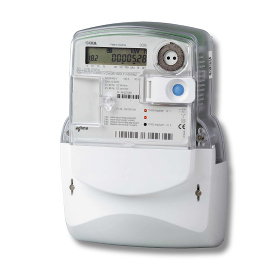
Page 10: Meter Appearance (Me37Y)
The meter cover is made of transparent polycar- Meter appearance bonate. A nickel-plated iron ring in the right top corner (ME37y) is utilized for attaching an optical probe to the optical port. There is a lid which is fixed to the meter cover with a hinge. -
Page 11: Overall And Fixing Dimensions (Me37Y)
100 A) is possible too. 2.2 Overall and fixing dimensions (ME37y) detectioion SD - Switching device Fig. 6: ME371 meter block diagram detection Fig. 5a: Overall and fixing dimensions of a meter fitted with a long terminal cover GSM/GPRS MODEM... -
Page 12: Metering System (Me37Y)
2.4 Metering system (ME37y) Besides precision measurement of active, reactive, apparent energy and demand in a wide metering and temperature range, the metering system enables measurement of phase voltages, currents and supply quality. One metering element is built in the meter. The current sensor is shunt, while voltage sensor is resistive voltage divider. -
Page 13: Meter Appearance (Mt37Y)
Meter appearance 3.2 MT372… (MT37y) 3.1 MT371… Fig. 9: MT372 meter constituent parts 1. LCD 8. A terminal cover 2. Technical data 9. A project number 3. Coupling circuit 10. A meter BAR code 4. A legend of registers 11. Impulse LEDs displayed on LCD Fig. - Page 14 height of 230 mm above the line connecting the bottom fixing holes (DIN 43857). Up to 6 auxiliary terminals (item 2) can be fitted in the right side of the current terminals. They can be meter cover made transparent utilized for M-Bus and OptoMOS relay impulse output polycarbonate.
-
Page 15: Overall And Fixing Dimensions (Mt371)
Double cage clamp Auxiliary terminals Fig. 12b: A terminal block with auxiliary terminals MT37y : 3x230/400 V, 10(120) A Fig. 14: Details of a terminal block for RS485 meter 1. RS485 comm. 6. Outputs for load control interface 2. Current terminals 7. -
Page 16: Overall And Fixing Dimensions (Mt372)
3.5 Overall and fixing dimensions (MT372) Mounting and fixing meter dimensions comply with the DIN 43857 standard. Fig. 15b: Overall and fixing dimensions of an MT371 meter fitted with a short terminal cover Fig. 17a: Overall and fixing dimensions of an MT372 meter fitted with a long terminal cover Fig. -
Page 17: Meter Configuration (Mt37Y)
10. GSM/GPRS with a bed 1.2.3. Three metering for a SIM card or RS485 elements (on request four) 3.6 Meter configuration (MT37y) communication interface 4. A meter power supply unit 11. Inputs; alarm 12.13. Outputs: relay, 5. A microcontroller with switching device control or 17. - Page 18 3. Two Rogowski coils 1. Rogowski coil frame (secondary winding) 2. Meter current loop 4. Printed circuit board (primary winding) The metering elements ensure excellent metering properties: 1. Wide metering range 2. Negligible influence of disturbances and influence quantities 3. Long-term stability so that meter re- calibration is not required over its life 4.
-
Page 19: Meter Configuration
4.2.1 Load-profile recorder Meter configuration A load-profile recorder can be provided with up to two channels. The following registration periods 15, 30 Meters consist of: and 60 minutes or a daily value can be set. In each 1. Metering system (items 2.4. and 3.7.) channel up to sixteen objects can be registered of which two are reserved for time and meter status. -
Page 20: Keeping Of Billing Results
4.2.3 Keeping of billing results 4.3.2 Maximum demand The meter keeps billing results (energy and demand The real-time clock generates a demand period. values registered by tariffs) in two billing profile, i.e. a Demand is calculated as an average value over the billing profile (billing profile 1) and a capture object demand period. -
Page 21: Signal Flags
push-button should be pressed for displaying the next piece of data. Data in Manual scroll sequence remains 4.4.2 Signal flags displayed until the blue push-button is pressed again or until time for automatic return into the Auto scroll The signal flags in the display bottom row indicate sequence is not elapsed. -
Page 22: Push-Buttons
the meter accuracy. Impulse constant depends on the 4.6.1 RESET and SCROLL push- meter version. button RESET push-button In normal meter operation mode, the LED emits pulses Push-button functions are: with frequency that is proportional to the measured power and is intended for the meter calibration and - Switching to the meter test operation mode testing. - Page 23 Meter reset Menu navigation The Reset (orange) and Scroll (blue) push-buttons After power up, a meter is in autoscroll mode. are used for resetting the meter by pressing Predefined menu is available by appropriate push- appropriate push-buttons, following predefined time button pressing ( Fig.
-
Page 24: Manual Meter Billing Reset
Display Test START t = 6 s 60 s no activity Auto Scroll 0-0:21.0.2 SCMD SCMD Display registers Display Test SCMD 0-0:21.0.1 SCMD Scroll key hold > 8s LEGEND: SD mode Release Scroll key Scroll key released and pressed again SD==Off Scroll key hold Credit... -
Page 25: Optical Port - Ir Communication Interface
billing or a data concentrator. Data transmission rate 4.7.1 Optical port – IR via network is 9600 baud/s, while actual data communication interface transmission rate depends on momentary conditions in network. A GSM antenna is built in the meter. It enables operation in three frequency ranges: •... -
Page 26: Rs485 Communication Interface (Option) (Mx372)
4.7.5 RS485 communication interface (option) (Mx372) A built-in communication interface enables setting of meter parameters and a local readout of measuring results. The protocol for data transfer is IEC 62056 – 46. 4.7.6 M-Bus communication Fig. 31b: Display legend, Mx372 and ME374 interface (option) (GSM/GPRS, RF communication interface, RS485) There is M-Bus communication interface integrated in... -
Page 27: Inputs And Outputs (Me37Y)
4.9 Inputs and outputs (ME37y) Communication is performed as follows: Meters can be equipped with up to ten auxiliary terminals. The following inputs and outputs are P2LPC Mx371 possible: • Two Alarm inputs (option) • Output for load control by a bistabile 6 A relay •... -
Page 28: Inputs
the terminal block. The meter with the switching device as a whole complies with the DIN 43857 MT372: Input-output connection terminals are placed standard or the stated fixing dimensions. on the right side of the meter terminal block as well as on the upper additional plate. -
Page 29: Additional Meter Functions
5.3 Scheduled reading of E- Additional meter meter functions The meter reading is scheduled later e.g. at the moment of a tariff changeover, or at an energy • Collection of energy consumption information in supplier switch. subsequent billing periods of individual customers and/or a (larger) number of customers. -
Page 30: Tariff Structure Configuration Of E-Meter
event log. The FF register is 32 bits long. It is 5.11 Remote customer organized in 4 groups of errors: connection/disconnection • Time base errors A plug-in switching device (ZO3…) is used for remote • Access data errors disconnection and reconnection of electric network to •... -
Page 31: Load-Profile Configuration Of G-Meter
5.15 Load-profile configuration COSEM Objects Phase L2 Failure Duration of G-meter Phase L3 Failure Duration Remote configuration of information saved in profiles Long Power Failures in any Phase Duration of individual customers and/or a larger number of Long Power Interruption Log customers. -
Page 32: Commission E-Meter
COSEM Objects accessed with commissioning: COSEM Objects Logical Name Class Description Auto dial Alarm ON status 0-0:96.1.8.255 Device ID 9 – Meter ID Alarm ON operations 0-0:96.1.1.255 Device ID 2 – ZIP code Alarm OFF status Alarm OFF operations 1-0:1.8.0.255 A+, Time Integral 1, Total, Current Billing Period Power Failure Alarm Filtering Limit... -
Page 33: Data Protection
Data protection Special attention is paid to a system of meter data protection in order to prevent meter tampering. Access to the billing data registers in order to change their values is not possible. Entering the RTC correction constant, meter configuration and auxiliary terminals can be performed only after entering an eight digit password and pressing the Param push- button that is under the meter cover. -
Page 34: Meter Connection Procedure
Meter connection 7.1 Connection procedure of procedure GSM/GPRS communication 1. The meter should be fixed with screws at the place interface of measurement. 2. The meter should be connected according to the Checking of the presence of a SIM card meter connection diagram that is attached to the 1. -
Page 35: Accessory For Meters Managing
• For meter reading and programming in the field: MeterRead (Iskraemeco software) for all types of hand-held computers (Palmtop PC), utilizing the Windows CE operation system Optical probe •... -
Page 36: Meter Maintaining
Meter maintaining No maintenance is required during the meters life. implemented metering technique, built-in components and manufacturing procedures ensure high long-term stability of meters, so that there is no need for their recalibration during their life. B0024445 Mx37y TEHNIČNI OPIS KOMAR DOBERLET Mx37y TECHNICAL DESCRIPTION... -
Page 37: Anti-Fraud Protection
Anti-fraud protection The meter cover and the meter terminal cover are sealed by means of sealing screws and conventional wire seals. Unless the seals are broken, the access into the meter enclosure is not possible. On customer’s demand the meter can be equipped with special internal switches for the detection of any lifting of the meter cover or meter terminal cover. -
Page 38: Front Plate
Front plate Fig. 43: ME374-D3 meter front plate Fig. 40: ME371-D3 meter front plate Fig. 41: MT372-D1 meter front plate Fig. 42: MT372-D2 meter front plate B0024445 Mx37y TEHNIČNI OPIS KOMAR DOBERLET Mx37y TECHNICAL DESCRIPTION 5.6.2009 020611325_003_000_AD.doc 020.611.325 38/45 Mx37y... -
Page 39: Meter Connection
Hardware type Function Terminal RS485 – GND RS485 – A RS485 – B RS485 – A RS485 – B Fig. 44: Connection diagram of ME371 meter Inputs Hardware type Function Terminal Common Low voltage Alarm input (up to 24 V, 27 mA) - Page 40 27 mA) Common Low voltage (up to 24 V, Transistor 27 mA) Inputs Hardware type Function Terminal Common Low voltage (up to 24 V, Alarm input 27 mA) Common Low voltage (up to 24 V, Alarm input 27 mA) Outputs Fig.
-
Page 41: Technical Data
RF communication interface Technical data IEEE 802.15.4 (2006) wireless communication standard GENERAL METER MEASURING CHARACTERISTICS Standard FCC Part 15.247 ETSI EN 300 328 - Active: 2 or 1 (IEC 62052-11) ETSI EN 300 489 Active: A or B (MID) Protocol robust custom networking protocol Accuracy class - Reactive: 3 or 2 (IEC 62052-11) - Page 42 DIMENSIONS ME37y meter: 200 x 132 x 82 mm Mass approx. 800 g MT371 meter 250 x 178 x 55 mm Mass approx. 1000 g MT371 meter with switching device: 310 x 178 x 108 mm Mass approx. 1650 g ME372 meter: 250 x 178 x 86 mm Mass...
- Page 43 MT37y-D2 Function Nominal Max. Diam Note Wire Screw Moment type voltage current IL1 – in 3x230/400 V 120 A Current Pozidriv (2) UL1 – aux 3x230/400 V Voltage Pozidriv (1) IL1 – out 3x230/400 V 120 A Current Pozidriv (2) IL2 –...
-
Page 44: Type Designation
Type designation Single-phase electronic meter Three-phase electronic meter With built-in DLC modem With built-in GSM/GPRS modem or RS485 With built-in RF communication interface Terminal block: Imax=85 A (DIN 43857) Terminal block: Imax=120 A (DIN 43857) Terminal block: Imax=100 A (BS 5685) Terminal block up to 6 A Active energy measurement, accuracy class 1 (MID B) Active energy measurement, accuracy class 2 (MID A) - Page 45 Iskraemeco d.d., Energy Measurement and Management 4000 Kranj, Savska loka 4, Slovenia Telephone (+386 4) 206 40 00, Fax: (+386 4) 206 43 76 http://www.iskraemeco.si, E-mail: info@iskraemeco.si Published: Iskraemeco, Marketing, Data subjected to alteration without notice. 020611325_003_000_AD 2 B0024445 Mx37y TEHNIČNI OPIS...
Need help?
Do you have a question about the ME371 and is the answer not in the manual?
Questions and answers