Sign In
Upload
Manuals
Brands
ISKRAEMECO Manuals
Measuring Instruments
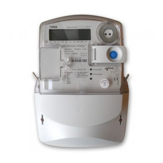
ME382
ISKRAEMECO ME382 Manuals
Manuals and User Guides for ISKRAEMECO ME382. We have
1
ISKRAEMECO ME382 manual available for free PDF download: Manual
ISKRAEMECO ME382 Manual (195 pages)
Brand:
ISKRAEMECO
| Category:
Measuring Instruments
| Size: 7 MB
Table of Contents
Table of Contents
8
1 Safety Information
16
Responsibilities
16
Safety Instructions
17
Handling and Mounting
17
Meter Installation Procedure
18
Meter Maintenance
22
2 Energy Metering and Mx382 Meters
23
Figure 1: Smart Metering System
23
3 Mx382 Meters Introduction
24
Standards and References
24
ME382 Meter Description
26
Figure 2: ME382 Meter Appearance - Front View
26
Figure 3: Terminal Block - ME382-D1 (85 A) DIN Connection
27
Figure 4: Terminal Block - ME382-D3 (100 A) BS Connection
27
Terminal Block Constituent Parts - ME382-D1 (85 A) DIN Connection
27
Terminal Block Constituent Parts - ME382-D3 (100 A) BS Connection
27
Figure 5: Terminal Block Constituent Parts - Common for D1 (DIN) and D3 (BS) Type
28
Terminal Block Constituent Parts - Common for D1 (DIN) and D3 (BS) Type
28
MT382 Meter Description
29
Figure 6: MT382 Meter Appearance - Front View
29
Figure 7: Terminal Block - MT382-D1/D2
30
Terminal Block Constituent Parts - MT382-D1/D2
30
Figure 8: Terminal Block - MT382-T1
31
Terminal Block Constituent Parts - MT382-T1
31
Main Meter Properties
32
Connection Diagram
34
Table 1: Auxiliary Terminals Designation
34
Figure 10: Me38Y-D3 Meter Connection Diagram - BS Connection
35
Figure 9: Me38Y-D1 Meter Connection Diagram - DIN Connection
35
ME382- D3 Meter
35
ME382-D1 Meter
35
Figure 11: Mt38Y Meter Connection Diagram - Direct Connection (Left), Transformer Connection (Right)
36
MT382 Meter
36
Energy and Demand Registration
37
Energy
37
Figure 12: Measured Energy and Demand
37
Demand
38
Figure 13: Demand Calculation Sample
38
Figure 14: Measuring Principle
38
Figure 15: Attributes in the Case of Block Demand (1 Period)
39
Figure 16: Attributes in Case of Sliding Demand
39
Figure 17: Time Attributes When Measuring Sliding Demand
40
Other Demand Registers
40
Table 2: Last Average Demand Registers
40
Table 3: Maximum Demand Registers - Total
40
Measurement Platform
41
Measuring Configuration
41
Table 4: Cumulative Maximum Demand Registers
41
Table 5: Average Demand Objects
41
Table 6: Measuring Configuration Type
41
Rogowski Coil
42
Shunt
42
Energy Metrological Pulse Output
42
Table 7: List of a Metropulse Output Functions
42
Transformer Measurement Type
42
Measured Quantities
43
Voltage
44
Average Voltage
44
Daily Peak and Minimum Values
44
Instantaneous Voltage
44
Table 10: Voltage Levels Counters
44
Table 11: Magnitude for Voltage Sags and Swells
44
Table 8: Peak and Minimum Values of Voltage
44
Table 9: Average Values of Voltage
44
Voltage Levels
44
Voltage Sags and Swells
44
Current
45
Instantaneous Current
45
Net Frequency
45
Power
45
Average Power
45
Instantaneous Power
45
Power Factor
45
Table 13: Instantaneous Power Objects
45
Table 14: Average Power
45
Energy
46
Total Energy Values
46
Measurement Period
46
Table 15: Total and Tariff Energy Objects
46
4 Meter Construction
47
Technical Figures and Dimensions of the ME382 Meter
47
Figure 18: Overall and Fixing Dimensions of the ME382-D1 Meter Fitted with a Regular Terminal Cover
47
Figure 19: Overall and Fixing Dimensions of the ME382-D3 Meter Fitted with a Regular Terminal Cover
47
Figure 20: Overall and Fixing Dimensions of the ME382-D1 Meter Fitted with a Short Terminal Cover
48
Figure 21: Overall and Fixing Dimensions of the ME382-D3 Meter Fitted with a Short Terminal Cover
48
Figure 22: Overall and Fixing Dimensions of the ME382-D1 Meter Fitted with a P1+M-Bus Terminal Cover
49
Figure 23: Overall and Fixing Dimensions of the ME382-D3 Meter Fitted with a P1+M-Bus Terminal Cover
49
Figure 24: Overall and Fixing Dimensions of an MT382 Meter Fitted with a Regular Terminal Cover
50
Figure 25: Overall and Fixing Dimensions of an MT382 Meter Fitted with a Short Terminal Cover
50
Technical Figures and Dimensions of the MT382 Meter
50
Figure 26: Overall and Fixing Dimensions of the MT382 Meter Fitted with an External SD Terminal Cover
51
Meter Case
52
Figure 27: Overall and Fixing Dimensions of the MT382 Meter Fitted with a P1+M-Bus+Sd Terminal Cover
52
Terminal Block
53
U-I Link between Voltage and Current Circuits
53
Figure 28: Sliding U-I Link (Left: Position Down; Right: Position Up)
54
Figure 29: Load Control Terminal
54
Inputs and Outputs
54
Figure 30: Signal Control Terminal
55
Figure 31: Mx382 Input Terminals
56
Figure 32: Output for Active SD
56
Input/Output Status
56
Output for Active Switching Device
56
Table 16: Input State Control Register of ME382 and MT382 Meter
56
Figure 33: Short Terminal Cover (Left) and Regular Terminal Cover (Right)
57
Meter Cover
57
Table 17: Output State Control Register of Single-Phase (ME382) Meter
57
Table 18: Output State Control Register of Three Phase (MT382) Meter
57
Terminal Cover
57
Figure 34: External SD Terminal Cover for the Meter with SD Unit (Left) and P1+M-Bus+Sd Terminal Cover (Right)
58
Figure 35: P1+M-Bus Terminal Cover (Left: with the Sealable Lid; Right: Without the Sealable Lid)
58
Figure 36: Meter Connection Diagram on the Inner Side of the Terminal Cover
58
Figure 37: Name Plate of the ME382 Meter
59
Name Plate
59
Figure 38: Name Plate of the MT382 Meter
60
Mx382 Meter Type Designation
61
Table 19: Meter Type Designation
61
5 Console
62
Lcd
62
Figure 39: Full Mx382 LCD - Display Fields
62
Figure 40: Displaying Value with Format "60
63
Figure 41: Displaying Value with Format "82
63
Table 20: LCD Cursors
63
Display Configuration
64
Figure 42: Signature on the Display
64
Table 21: Display Configuration for Octet 0 Definition
64
Table 22: Display Configuration for Octet 1 Definition
64
Metrological Leds
65
Figure 43: Leds at the ME382 Meter
65
Figure 44: Leds at the MT382 Meter
65
Table 23: LED Constants Recommendation
65
Buttons
66
Figure 45: Scroll Button (on the Left) Reset and Scroll Button (on the Right)
66
Table 24: Button Labels
66
Reduced Console Menu Type
67
Table 25: Use of Scroll Button in Reduced Console Menu Type
67
Table 26: Scroll Button Extended Press
67
Alternate Display Readout Mode
68
Figure 46: Menu Navigation Diagram - Reduced Console Menu Type
68
General Display Readout Mode
68
Normal Console Menu Type
69
Table 27: Use of Buttons in Normal Console Menu Type
69
Figure 47: Entering the Data/Set Menu
70
Data Menu
71
Figure 48: Data Menu Navigation
71
Figure 49: Alternate Display Readout Mode Navigation in Normal Console Menu Type
71
Table 28: Register Reading Procedure on the LCD When the Reduced Console Menu Type Is Set
72
Table 29: Register Reading Procedure on the LCD When the Normal Console Menu Type Is Set
72
Figure 50: Load Profile on Display Navigation
73
Figure 51: Certification Data Log on Display Navigation
74
Set Menu
74
Figure 52: Set Menu Navigation
75
Figure 54: LCD Test Mode Navigation
75
Figure 55: Previous Values Navigation in Alternate Display Readout Mode
76
Previous Values on a Display
76
6 Communication
77
Optical Interface
77
Figure 56: Optical Interface (Left); Optical Sonda (Right)
77
P1 Interface
78
Figure 57: Diagram for Connecting Devices to the P1 Port
78
P1 Functionality
79
Table 30: RJ11 Pins
79
P1 Parameters
80
M-Bus
80
Table 31: M-Bus Profile Status Registers Notifications
82
GSM/GPRS/UMTS Communication Module
84
Modem Initialization
84
Table 32: M-Bus Alarms
84
GSM/GPRS Network Diagnostic
85
Table 33: GSM/GPRS Modem Diagnostics Objects
85
Table 34: Network Signal Strength
85
CSD Data Connection (GSM)
86
Table 35: GSM Status Object Bit Assignment
86
Packet Data Connection (GPRS)
87
Short Message Service (SMS)
89
SMS Initialization
89
Table 36: SMS Centre Address Phone Number Setting
89
SMS Application Protocol Data Unit (APDU)
90
Table 37: Phone Number Example
90
Outgoing SMS
91
Table 38: Push Setup List
91
Incoming SMS
92
Table 39: DCS Settings
92
Table 40: VP Settings
92
Concatenated SMS
93
SMS Wake-Up Request (Empty Incoming SMS)
93
Table 41: Example of SMS PDU for Setting Object 0-0:96.13.0
93
Table 42: Concatenated SMS
93
Modem Reset
94
Table 43: Modem Reset Triggers
95
TCP/IP Based COSEM Communication Profile
97
Table 44: COSEM Wrapper Header Information
98
GSM/GPRS Connection Management
99
Auto Connect
99
Auto Answer
100
Table 45: Auto Connect Modes
100
Table 46: Modem Working Mode
101
Table 47: Window Status
101
Table 48: GSM Status Object Bits B1 and B11 Relation States and Meaning
102
Selecting the Cellular Network (2G/3G)
103
Table 49: GSM Network Name
103
Push
104
Push Objects
104
Data Notification Service
105
Push Process
105
Push Related Functionalities
106
7 Description of Main Meter Functionalities
107
Measurements
107
Sequences
107
Main Load Profiles
107
Table 50: Profile Status Register
108
Load Profile Options
109
Billing
109
Table 51: Load Profile Options Bit Values
109
Billing Profile
110
Prepayment
111
Event Logs
114
Standard Event Log
115
Table 52: Event Log Objects
115
Fraud Detection Log
116
Table 53: List of Events in the Standard Event Log
116
Disconnector Control Log
117
Table 54: List of Events in the Fraud Detection Event Log
117
Table 55: List of Events in the Disconnector Control Log
117
M-Bus Event Log
118
Table 56: List of Events in the M-Bus Event Log
118
Power Quality Log
119
Communication Event Log
119
Table 57: List of Events in the Power Quality Event Log
119
M-Bus Master Control Logs
120
Table 58: List of Events in the Communication Event Log
120
Table 59: List of Events in the M-Bus Control Log
120
Power Failure Event Log
121
Certification Data Log
121
Table 60: Power Failure Event Log
121
Table 61: Last Modified Secure Parameter Identifier
121
Table 62: Last Modified Secure Parameter Old Value
121
Table 63: Last Modified Secure Parameter New Value
121
Alarms
122
Table 64: Monitored Critical Parameters
122
Table 65: Alarm 1 Codes
123
RTC Backup
124
Table 66: Alarm 2 Codes (IDIS P2)
124
Time
125
Time Management
125
Errors
126
Table 67: IDIS Error Codes Register
126
Error Filter
127
Error Types
127
Table 68: IE Error Codes Register
127
Activity Calendar and TOU Registration
128
Activity Calendar
129
Tariff Program
129
Tariff Synchronization
130
Tariffication Script Table
130
Tariff Switch Source
130
Manual Tariffication Script Activation
130
Switching Device
130
Switching Device Type Designation
131
Table 69: Type Designation for ZO350-D1/D2
131
Disconnect Control
132
Manual Option
133
Manual Reconnection
133
Manual Disconnection
134
By the External Button
135
Remote Disconnection
135
Remote Option
135
Remote Reconnection
135
Limitation
136
Limiter
136
Advanced Power Limitation
137
Supervision Monitor - IDIS
138
Supervision Monitor - GIZ
138
Overvoltage Monitor and Load Disconnection
139
Fraud Detection
140
Meter Cover Open and Terminal Cover Open
140
Magnetic Field Detection
140
Identification Numbers
140
COSEM Logical Device Name
140
System Title
141
Device Number
141
Table 70: the IDIS Device Type Meaning
141
Table 71: the IDIS Function Type Meaning
141
Table 72: COSEM Logical Device Name Example
141
Device ID
142
Meter Software Identification
142
Software Architecture
142
Table 73: Meter Device Ids
142
E-Meter Signatures
143
Table 74: Meaning of Revision Number Characters
143
Monitoring Functions
144
Power Quality
144
Table 75: Dip & Swell Detection Model
144
Voltage Level
144
Table 76: Daily Peak and Minimum Counters
145
Voltage Asymmetry
145
Asymmetrical Voltage (Optional)
146
Asymmetric Current
147
Neutral Missing Detection
147
Unexpected Consumption
147
Neutral Fault (Optional)
148
Time Period for Asymmetry Voltage and Neutral Fault
148
Capturing of Voltage Values
149
Power Failure
149
Wrong Phase Sequence
149
Watchdog Counter
150
8 Security
151
Physical Security
151
Seal Protection
151
Parameter Protection Button
152
Logical Security
152
DLMS/COSEM Security
152
Table 77: Set of Supported Clients
153
Table 78: Supported Authentication Mechanism Names
153
Table 79: Application Context Names
154
Table 80: Security Suite
154
9 Firmware Upgrade
155
10 Application Association
157
SAP Assignment
157
Table 81: COSEM SAP Assignment Example
157
11 Technical Characteristics
158
ME382 Meter
158
MT382 Meter
161
Switching Device for the MT382 Meter
164
12 Annex
165
Annex 1: Relay, SD and M-Bus Disconnect States and Transitions
165
Table 82: Disconnect Control Modes
165
Annex 2: ME382 Object List
166
Annex 3: MT382 Object List
180
Advertisement
Advertisement
Related Products
ISKRAEMECO ME371
ISKRAEMECO ME372
ISKRAEMECO ME374
ISKRAEMECO MT382
ISKRAEMECO MT371
ISKRAEMECO MT880
ISKRAEMECO MT880-D2
ISKRAEMECO MT880-T1A32R46S43-E12-V52L81B11-M3K03-M
ISKRAEMECO MT831
ISKRAEMECO MT372
ISKRAEMECO Categories
Measuring Instruments
Battery Charger
Gateway
More ISKRAEMECO Manuals
Login
Sign In
OR
Sign in with Facebook
Sign in with Google
Upload manual
Upload from disk
Upload from URL