Table of Contents
Advertisement
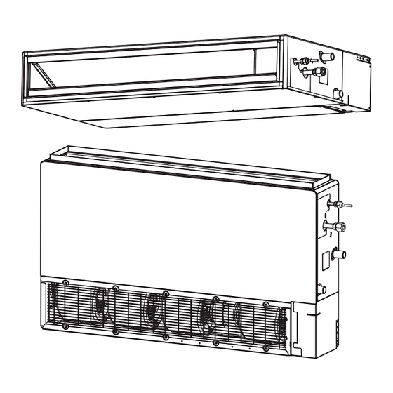
AIR CONDITIONER
INDOOR UNIT
Slim Duct Type
INSTALLATION MANUAL
For authorized service personnel only.
Contents
1. SAFETY PRECAUTIONS ............................................. 2
1.1. IMPORTANT! Please Read Before Starting ........... 2
1.2. Special precautions ................................................ 2
2. ABOUT THIS PRODUCT .............................................. 3
2.1. Precautions for using R410A refrigerant ................ 3
2.2. Special tools for R410A .......................................... 3
2.3. For authorized service personnel only. .................. 3
2.4. Accessories ............................................................ 4
2.5. Optional parts ......................................................... 5
3. GENERAL SPECIFICATIONS ...................................... 5
3.1. Type of copper pipe and insulation material ........... 5
3.2. Additional materials required for installation........... 5
3.3. Operating range ..................................................... 5
4. ELECTRICAL REQUIREMENT ..................................... 6
5. SELECTING THE MOUNTING POSITION ................... 6
6. INSTALLATION WORK ................................................. 7
(Ceiling concealed type) ...................................... 7
Floor standing concealed type) ........................... 7
6.2A. Install the unit (Ceiling concealed type) ............... 7
Floor standing concealed type) ......................... 10
7. PIPE INSTALLATION .................................................. 12
7.1. Selecting the pipe material ................................... 12
7.2. Pipe requirement .................................................. 12
7.3. Flare connection (Pipe connection)...................... 12
7.4. Installing heat insulation ....................................... 13
8. INSTALLING DRAIN PIPES ........................................ 14
8.1A. When drain pump is used .................................. 14
(Natural drainage) .............................................. 14
8.2. Install the drain pipe ............................................. 15
9. ELECTRICAL WIRING ................................................ 16
9.1. INDOOR UNIT SIDE ............................................ 17
10. REMOTE CONTROLLER SETTING ........................... 18
10.1. Installing the remote controller ........................... 18
10.2. Setting the dip switches ..................................... 19
10.3. Function setting .................................................. 19
10.4. Jumper wire setting ............................................ 22
10.5. Test run .............................................................. 22
11. SPECIAL INSTALLATION METHODS ......................... 23
12. OPTIONAL PARTS ..................................................... 23
12.1. External input and external output ..................... 23
12.2. Remote sensor (Optional parts) ......................... 24
12.3. IR Receiver Unit (Optional parts) ....................... 24
13. ERROR CODES ......................................................... 25
14. CUSTOMER GUIDANCE ............................................ 26
PART No. 9374342419-02
Advertisement
Table of Contents

Subscribe to Our Youtube Channel
Related Manuals for Fujitsu AR 7


Summary of Contents for Fujitsu AR 7
-
Page 1: Table Of Contents
AIR CONDITIONER INDOOR UNIT Slim Duct Type INSTALLATION MANUAL For authorized service personnel only. Contents 7. PIPE INSTALLATION ..........12 1. SAFETY PRECAUTIONS ..........2 7.1. Selecting the pipe material ........12 1.1. IMPORTANT! Please Read Before Starting ... 2 7.2. -
Page 2: Safety Precautions
All Fujitsu General products are manufactured to metric units and When Transporting tolerances. United States customary units are provided for reference only. In cases where exact dimensions and tolerances are required, Be careful when picking up and moving the indoor and out- always refer to metric units. -
Page 3: About This Product
Copper pipes 2. ABOUT THIS PRODUCT It is necessary to use seamless copper pipes and it is desirable that the amount of residual oil is less than 0.0014 2.1. Precautions for using R410A refrigerant oz/10 m (33 ft). Do not use copper pipes having a collapsed, deformed or discolored portion (especially on the interior sur- The basic installation work procedures are the same as face). -
Page 4: Accessories
2.4. Accessories Name and Shape Q’ty Application Filter (Small) WARNING (AR7/9/ For installation purposes, be sure to use the parts supplied by 12/24) the manufacturer or other prescribed parts. The use of non-prescribed parts can cause serious accidents such as the unit to fall, water leakage, electric shock, or fi re. Filter (Big) The following installation parts are furnished. -
Page 5: Optional Parts
1/4 in. (6.35 mm) 5/8 in. (15.88 mm) • Use pipe with water-resistant heat insulation. • All Fujitsu General products are manufactured to metric units and tolerances. United States customary units are pro- vided for reference only. In cases where exact dimensions and tolerances are required, always refer to metric units. -
Page 6: Electrical Requirement
Withstandable weight (9) Take servicing, etc., into consideration and leave the spaces. MODEL Also install the unit where the fi lter can be removed. (Unit weight x 3*) AR 7/9/12 120 Lbs (54kg) AR 18 153 Lbs (69kg) AR 24 179 Lbs (81kg) *In accordance with UL standards. -
Page 7: Installation Work
6.1B. Installation dimensions (Wall mounted 6. INSTALLATION WORK type/Floor standing concealed type) 6.1A. Installation dimensions (Ceiling The wall mounted type/floor standing concealed type re- concealed type) quires a temperature correction setting. Perform this in “10.3. Function setting”. Provide a service access for inspection purposes. Do not place any wiring or illumination in the service space, unit: in. - Page 8 Side Inlet - Side Outlet CAUTION Insulation material (Field supply) Check that duct work does not exceed the range of external Aluminum tape static pressure of equipment. Flange (Field supply) Make sure to insulate ducts to avoid condensation. Make sure to insulate between ducts and walls if metal ducts are used.
- Page 9 6.2A.2. INSTALL THE FILTERS 6.2A.4. FIX THE UNIT (1) Hang the unit • Install the fi lters to the unit. • Use hanger bolts of size M8 or M10 (5/16 or 3/8 in.). Hanger Hanger bolt Nut A (Field supply) Washer (Ac- cessories) Nut B (Field...
-
Page 10: Install The Unit (Wall Mounted Type/Floor Standing Concealed Type)
Level gauge 6.2B.1. UNIT INSTALLATION EXAMPLE (Wall mounted type/Floor standing concealed type) Connect the locally purchased duct. (1) Inlet side • Connect the duct to the locally purchased inlet fl ange. • Connect the fl ange to the body with the locally purchased tapping screws. - Page 11 6.2B.2. INSTALL THE FILTERS 6.2B.3. INSTALL THE UNIT • Install the fi lters (Accessories) to the unit. • To prevent overturning, attach the unit to the fl oor or the wall. • To avoid vibration of the unit, install vibration isolation pad between the unit and the fl...
-
Page 12: Pipe Installation
7.2. Pipe requirement 7. PIPE INSTALLATION CAUTION CAUTION Refer to the Installation Manual of the outdoor unit for description of the length of connecting pipe or for difference Be careful that foreign matter (oil, water, etc.) does not enter of its elevation. the piping with refrigerant R410A models. -
Page 13: Installing Heat Insulation
Check if [L] is fl ared uniformly CAUTION and is not cracked or scratched. Connect the piping so that the control box cover can easily be removed for servicing when necessary. In order to prevent water from leaking into the control box, make sure that the piping is well insulated. -
Page 14: Installing Drain Pipes
8.1B. When drain pump is not used (Natural 8. INSTALLING DRAIN PIPES drainage) WARNING CAUTION Do not insert the drain piping into the sewer where sulfurous gas occurs. (Heat exchange erosion may occur) Set “Drainage function setting (JM1)” in “10.4. Jumper wire set- ting.”... -
Page 15: Install The Drain Pipe
(2) Wall mounted type / Floor standing concealed type (2) Be sure to connect Drain pipe with adhesive (polyvinyl chloride) so that there is no leakage. Applying Downward gradient 0.10- Joint pipe area of 0.19 in. (2.5-5.0 mm) (Field supply) adhesive 3-15/16 in. -
Page 16: Electrical Wiring
Slit 9. ELECTRICAL WIRING Press fi rmly Press fi rmly WARNING Before starting work, check that power is not being supplied to the indoor unit and outdoor unit. Match the terminal board numbers and connection cord colors Roll the in- sulation over with those of the outdoor unit or branch box. -
Page 17: Indoor Unit Side
9.1. INDOOR UNIT SIDE (1) Remove the control box cover from the control box. Cable tie (Small) Cover (Accessories) Remote controller cable Screw Conduit (Field supply) Power supply cable (2) Cable connection • Connect the connection cable to the terminal board. (3) Wiring system diagram •... -
Page 18: Remote Controller Setting
10. REMOTE CONTROLLER SETTING 1. Red 2. White Hole 3. Black CAUTION When detecting the room temperature Temperature CAUTION using the remote controller, please Cable tie sensor (Small) set up the remote controller accord- When connecting the ing to the following conditions. If the remote controller wires, do remote controller is not located prop- not overtighten the screws. -
Page 19: Setting The Dip Switches
(2) Press the SET BACK button to select the indoor unit num- 10.2. Setting the dip switches ber. SET BACK Set the remote controller DIP switches. [Example] Front case (back side) SU MO TU WE TH FR SA DIP switch 1 Unit number of INDOOR UNIT (★... - Page 20 10.3.1. Function Details Room temperature sensor switching Filter sign (Only for Wired remote controller) When using the Wired remote controller temperature sensor, Select appropriate intervals for displaying the fi lter sign on the change the setting to "Both" (01). indoor unit according to the estimated amount of dust in the air of the room.
- Page 21 10.3.2. Temperature Correction Room temperature control for wired remote con- troller sensor NOTE: Depending on the installed environment, correction of the wire When changing Function 95, perform this setting before other remote temperature sensor may be required. Room temp. control settings (Function 30, 31, 92, 93). Select the appropriate control setting according to the in- If Function 95 is not set fi...
-
Page 22: Jumper Wire Setting
SETTING THE ROOM TEMPERATURE (2) Fan delay setting (JM3) DETECTION LOCATION It is a function to delay the stop of cooling fan when the air conditioner is stopped. The location of the sensor detecting the room temperature (♦... Factory setting) can be selected from the following 2 examples. -
Page 23: Special Installation Methods
[Using the wireless remote controller for test 12. OPTIONAL PARTS run] (Option) WARNING • For the operation method, refer to the operating manual. Refer to local codes for acceptable cable type. • The outdoor unit may not operate depending on the room temperature. -
Page 24: Remote Sensor (Optional Parts)
12.2. Remote sensor (Optional parts) 12.3. IR Receiver Unit (Optional parts) Connection method Connection method • Connection terminals • Connection terminals Receiver unit terminal (CN13) • Wiring arrangement Remote sensor terminal (CN8) Cable tie • Wiring arrangement Cable tie • Use 7 pins for receiver unit cable. •... -
Page 25: Error Codes
13. ERROR CODES If you use a wired remote controller, error codes will appear on the remote controller display. If you use a wireless remote con- troller, the lamps on the IR receiver unit will output error codes by way of blinking patterns. See the lamp blinking patterns and error codes in the following table. -
Page 26: Customer Guidance
[Troubleshooting at the remote controller LCD] This is possible only on the wired remote controller. [Self-diagnosis] If an error occurs, the following display will be shown. (“Er” will appear in the set room temperature display) Error code EX. Self-diagnosis 14. CUSTOMER GUIDANCE Explain the following to the customer in accordance with the operating manual: (1) Starting and stopping method, operation switching,...
Need help?
Do you have a question about the AR 7 and is the answer not in the manual?
Questions and answers