Do you have a question about the AB12 and is the answer not in the manual?
Questions and answers
A.D.Mishra
May 1, 2025
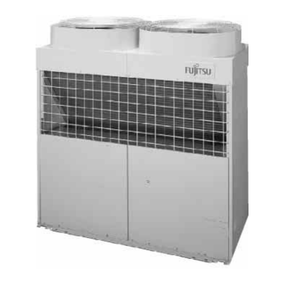
aircon is not cooling and compressor getting hot and tripping
1 comments:
Mr. Anderson
May 16, 2025
A Fujitsu AB12 air conditioner may not cool, have a hot compressor, and trip due to the following possible causes:
1. Electronic expansion valve open excessively: This can lead to abnormal refrigerant flow, causing the indoor unit to ice and the compressor to overheat or malfunction.
2. Faulty electronic expansion valve: If the valve is not opening or closing properly, refrigerant flow may be disrupted, leading to poor cooling and compressor issues.
3. Icing at the indoor unit heat exchanger: This can restrict airflow and cause the compressor to overwork and overheat.
4. Faulty thermistor (temperature sensor): An outdoor or heat exchanger thermistor error can cause incorrect readings and improper system control, which may lead to compressor overheating and tripping.
5. Fan operating in “FAN” mode only: If set to “FAN” mode, the system circulates air without cooling, potentially causing the compressor to run inefficiently or overheat.
These conditions can result in the unit failing to cool, a hot compressor, and possible system tripping.


Need help?
Do you have a question about the AB12 and is the answer not in the manual?
Questions and answers
aircon is not cooling and compressor getting hot and tripping
A Fujitsu AB12 air conditioner may not cool, have a hot compressor, and trip due to the following possible causes:
1. Electronic expansion valve open excessively: This can lead to abnormal refrigerant flow, causing the indoor unit to ice and the compressor to overheat or malfunction.
2. Faulty electronic expansion valve: If the valve is not opening or closing properly, refrigerant flow may be disrupted, leading to poor cooling and compressor issues.
3. Icing at the indoor unit heat exchanger: This can restrict airflow and cause the compressor to overwork and overheat.
4. Faulty thermistor (temperature sensor): An outdoor or heat exchanger thermistor error can cause incorrect readings and improper system control, which may lead to compressor overheating and tripping.
5. Fan operating in “FAN” mode only: If set to “FAN” mode, the system circulates air without cooling, potentially causing the compressor to run inefficiently or overheat.
These conditions can result in the unit failing to cool, a hot compressor, and possible system tripping.
This answer is automatically generated