Table of Contents
Advertisement
Quick Links
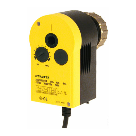
AVM 105S, 115S: Actuator with SAUTER Universal Technology (SUT)
How energy efficiency is improved
Automatic adaptation to valve, precision control and high energy efficiency with minimal operating
noise.
Areas of application
Actuation of through and three-way valves of the VUN/BUN, VUD/BUD and VUE/BUE series (DN15 to
DN50). For controllers with continuous output (0...10 V) or switching output (2-point or 3-point control).
Features
Pushing force 250 N (AVM 105S) or 500 N (AVM 115S)
Stepping motor with SUT (SAUTER Universal Technology) electronic control unit and
electronic load-dependent cut-off
Automatic detection of control signal applied (continuous or switching)
The type of characteristic curve (linear, quadratic or equal percentage) can be set in the actuator
Independent adaptation to valve stroke
Direction of travel can be set on cable
Coding switch for selection of characteristic and running time (35, 60 or 120 s)
Maintenance-free transmission with magnetic clutch
Transmission can be disengaged for positioning the valve manually (Allen key included)
Assembly with valve is done automatically after control voltage is applied
Technical description
24 V~ or 24 V~/= power supply
Two-part housing made of fire-retardant plastic; lower section black, upper section yellow
Console made of glass-fibre-reinforced plastic
Brass box nut for fitting valve
Connecting cable 1.2 m long, 5 × 0.75 mm²
Installation position: vertical to horizontal, but not upside down
Type
Running time
[s]
For valves with equal-percentage characteristic, can be switched over to linear
AVM 105S F132
35/60/120
AVM 115S F132
60/120
1)
Positioner
Control signal
Positional feedback signal
Power supply
24 V
24V=
Power consumption
AVM 105S F132
AVM 115S F132
Max. media temperature
Ambient temperature
Ambient humidity
For control valve type KTM512 / TA-Regulator DN 15...50
Type
Running time
[s]
AVM 115S F901
80/160
Deviation from standard type: inverse scale therefore inverse direction of operation. Adaptor for
control valve available on the valve or from TA-Regulator, stating reference no. 52 757 003.
1)
Also for 2-point or 3-point, depending on type of connection
2)
Maximum stroke of drive = 10.0 mm
2)
Stroke
Pushing force
[mm]
8.0
8.0
0...10 V, R i > 100 k
0...10 V, load > 10 k
± 20%, 50/60 Hz
+20% / –10%
4.8 W
8.5 VA
4.9 W
8.7 VA
100 °C
–10...55 °C
5...95% rh
without condensation
Stroke
Pushing force
[mm[
10.0
Power
[N]
250
24 V~/=
500
24 V~/=
Starting point U
0 or 10 V
0
Control span U
10 V
Switching range X
200 mV
sh
Degree of protection
IP 54 as per EN 60529
(horizontal)
Protection class
III as per IEC 60730
1)
Response time
200 ms
A09673
M09743
Fitting instructions 1 . 5S MV 506065
Material declaration
MD 51.362
Power
[N]
500
24 V~
Sauter Components
100 %
0 %
Weight
[kg]
0.7
0.7
Weight
[kg]
0.7
51.362/1
M
Y07552
0 V
Output signal y
10 V
B07650
7151362003 05
Advertisement
Table of Contents

Related Manuals for Sauter Components AVM 105S


Summary of Contents for Sauter Components AVM 105S
- Page 1 DN50). For controllers with continuous output (0…10 V) or switching output (2-point or 3-point control). Features Pushing force 250 N (AVM 105S) or 500 N (AVM 115S) Stepping motor with SUT (SAUTER Universal Technology) electronic control unit and electronic load-dependent cut-off ...
- Page 2 51.362/2 AVM 105S...115S Accessories 0313529 001* Split-range unit for setting sequences; to be fitted in separate distribution box as per MV 505671 0372145 001* Single auxiliary change-over contacts ; MV 505795 0372145 002* Double auxiliary change-over contacts ; MV 505795 0372249 001* Intermediate piece required for media temperature >100 °C...
- Page 3 51.362/3 AVM 105S...115S After power has been applied, the stepping motor moves to the lower stop, connects to the valve spindle and moves to the upper stop in the valve, thereby determining the closed position. Depending on the control voltage, any stroke between 0 and 8 mm can then be obtained. Thanks to the electronics unit, no steps can be lost, and the drive needs no periodical re-adjustment.
- Page 4 51.362/4 AVM 105S...115S Coding switch for selecting the characteristic AVM 115S Desired Characteristic Characteristic Switch coding Effective on valve character. curve for valve curve for drive curve Stroke 1 2 3 Signal Signal Stroke Stroke 1 2 3 Signal Signal...
- Page 5 Switch rating: max. 230 V a.c.; min. current 20 mA at 20 V Switch rating: max. 4...30 V d.c.; current 1...100 mA Power consumption: Type Running time Condition Active power P Apparent power S [VA] AVM 105S F132 Operating 2.45 4.75 Standstill 0.35 Operating Standstill 0.35 Operating 4.25...
- Page 6 51.362/6 AVM 105S...115S Wiring diagram RD = red BN = brown BK = black BU = blue GY = grey A10450 Dimension drawing 0372249 001 372145, 372286 Ø33 Ø8 Ø42 Ø16 Z10214 372273 126,7 15,5 M09743b M10203 Accessories 372145 001...
Need help?
Do you have a question about the AVM 105S and is the answer not in the manual?
Questions and answers