IRIS 700 Series Applications Manual

IRIS 700 Series Applications Manual

Flame monitoring system, signal processor and viewing head
Table of Contents

Advertisement

IRIS MODEL 700/800 APPLICATION MANUAL
FLAME MONITORING SYSTEM
MODEL 700 / 800 SIGNAL PROCESSOR AND VIEWING HEAD
APPLICATION MANUAL
PAGE 1

Advertisement

Table of Contents
loading
Need help?

Need help?

Do you have a question about the 700 Series and is the answer not in the manual?

Questions and answers

Summary of Contents for IRIS 700 Series

  • Page 1 IRIS MODEL 700/800 APPLICATION MANUAL FLAME MONITORING SYSTEM MODEL 700 / 800 SIGNAL PROCESSOR AND VIEWING HEAD APPLICATION MANUAL PAGE 1...
  • Page 2: Table Of Contents

    IRIS MODEL 700/800 APPLICATION MANUAL TABLE OF CONTENTS GENERAL DESCRIPTION ..................... 4 IR DETECTOR ........................ 5 UV DETECTOR ......................5 SELF-CHECKING......................5 INTERNAL PARAMETER STORAGE ................5 MODEL 700 POWER CONNECTIONS ................6 VIEWING HEAD CONNECTOR AND WIRING ............... 6 PROTECTING THE VIEWING HEAD CABLE ..............
  • Page 3 IRIS MODEL 700/800 APPLICATION MANUAL FIGURE AND FLOW CHART INDEX FIGURE 1 - MODEL 700AC SIGNAL PROCESSOR ........... 13 FIGURE 2 - MODEL 700AC SIGNAL PROCESSOR WIRING ........14 FIGURE 3 - MODEL 700DC SIGNAL PROCESSOR ........... 15 FIGURE 4 - MODEL 700DC SIGNAL PROCESSOR WIRING ........16 FIGURE 5 - MODEL 800 SIGNAL PROCESSOR ON DIN RAIL ........
  • Page 4: General Description

    IRIS MODEL 700/800 APPLICATION MANUAL GENERAL DESCRIPTION lar to those used to lock the legs of camera tripods. The IRIS Model 700AC, Model 700DC and Model 800 The IR/flicker sensitive viewing heads have a high pass- are single-channel, fail-safe, flame monitoring systems.
  • Page 5: Ir Detector

    IRIS MODEL 700/800 APPLICATION MANUAL IR DETECTOR parity to the viewing head. The viewing head sends back an ID pulse in the first half of the 100ms self- The models S702 and S802 viewing heads use the same check time. One viewing head expects to receive data...
  • Page 6: Model 700 Power Connections

    This cable does not have to be used in a check relay and the flame relay. This circuitry is de- conduit. It is labeled: IRIS SYSTEMS INC. C-330 signed so that any component failure will cause the E193849 (UL) TYPE ITC 4/C 18 AWG 90C 300V flame relay to open.
  • Page 7: Protecting The Viewing Head Cable

    Cdt02 flexible conduit, and two Con74s will be needed. be provided. IRIS will supply the 700 LTA. IRIS can also supply the SETTING THE VIEWING HEAD GAIN Cdt02 and Con74s, or these parts can be purchased commercially.
  • Page 8: Adjustment Of Vh Sighting And Gain

    Adjustment can be made range of orifice sizes; each size step results in about easier by a 1/2” swivel joint, which IRIS can supply if a 2:1 change in the counts displayed. one is not available. While the burner is firing, vary the viewing angle while observing the green LED on MANUAL SETUP OF SET POINTS –...
  • Page 9: Automatic Setup - Model 700 Only

    RS-232 bus in a multi-drop hookup. (%) is set to 50% (the factory default values) the relay The IRIS programmer could be mounted nearby and will close if the displayed count goes to 16 or higher and permanently connected to the same RS-232 bus;...
  • Page 10: Filter Selection For Ir Viewing Head

    IRIS MODEL 700/800 APPLICATION MANUAL After BNR-ON data sampling is complete, the OFF RELAY ON SET-POINT SEQ LED flashes. You should turn off the burner and immediately press the BNR-OFF SEQ START/END RATIO (%) RELAY OFF/RELAY ON key (a two-second press is not required). The displayed timer then counts down from 29.
  • Page 11: Setting Ffrt - Models 700 And 800

    IRIS MODEL 700/800 APPLICATION MANUAL shown in Table 1 being loaded and stored in EEPROM: Note that the actual maximum level for the current out- put is 19.8 MA. It is slightly less than 20 MA so that a In the Model 700, if the AUTO SET LED is on when...
  • Page 12: Model 700 Communications

    700 signal processors. This software for PCs is avail- approved as sealed and corrosion resistant to NEMA 4 able from IRIS on a CD ROM at no charge. However, to and NEMA 4X by Factory Mutual. interface from a PC to the RS-422 bus, an RS-232 to CONTACT INFORMATION RS-422 converter is needed.
  • Page 13: Figures 1-16 And Flow Charts 1-9

    IRIS MODEL 700/800 APPLICATION MANUAL RELAY CONNECTIONS RS422 WIRING 35mm DIN RAIL 5.49" APPROVED DIN RAIL RELEASE .25" 3.25" 2.90" FIGURE 1 - MODEL 700AC SIGNAL PROCESSOR PAGE 13...
  • Page 14: Figure 2 - Model 700Ac Signal Processor Wiring

    IRIS MODEL 700/800 APPLICATION MANUAL +26VDC AC POWER SUPPLY -t° .125 A APPROVED CHASSIS, EARTH, OR 0-20 OR 4-20 MA SYSTEM GND FOR INDICATOR OR INSTRUMENTATION 360 OHMS MAX TO VIEWING HEAD AC IN 24 V BACKUP BATTERY (OPTIONAL) GROUND...
  • Page 15: 
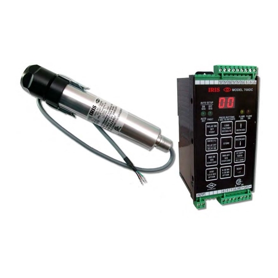
Figure 3 - Model 700Dc Signal Processor

    IRIS MODEL 700/800 APPLICATION MANUAL RELAY CONNECTIONS RS-422 WIRING 35mm DIN RAIL 5.49" APPROVED DIN RAIL RELEASE .25" 3.25" 2.90" FIGURE 3 - MODEL 700DC SIGNAL PROCESSOR PAGE 15...
  • Page 16: Figure 4 - Model 700Dc Signal Processor Wiring

    IRIS MODEL 700/800 APPLICATION MANUAL +26VDC .125 A APPROVED 0-20 OR 4-20 MA FOR INDICATOR OR INSTRUMENTATION 360 OHMS MAX CHASSIS, TO VIEWING EARTH, OR HEAD SYSTEM GND DC POWER SUPPLY 24 V BACKUP BATTERY 250 MA (OPTIONAL) FIGURE 4 - MODEL 700DC SIGNAL PROCESSOR WIRING...
  • Page 17: Figure 5 - Model 800 Signal Processor On Din Rail

    8 0 0 PROGRAM FLAME RELAY CONTACTS: FLAME 5A: 125VAC, 250VAC, 30VDC MONITOR RESET IRIS SYSTEMS DELTA, BC, CANADA 800-667-IRIS 85-265VAC 50-60 Hz MFG: JB SYSTEMS, INC. LARGO, FL 727-545-3900 .58" 1.56" 3.48" FIGURE 5 - MODEL 800 SIGNAL PROCESSOR ON DIN RAIL...
  • Page 18: Figure 7 - Model S702 And S706 Viewing Heads

    IRIS MODEL 700/800 APPLICATION MANUAL 1/2" - 14 NPT FOR SIGHTING PIPE HEX 1.50" ACROSS FLATS 1.76" DIA MOUNTING BLOCK 1/4" - 18 NPT FOR PURGE AIR 8.30" 6.41" 1.42" 0.33" 1.48" DIA FIGURE 7 - MODELS S702 AND S706 VIEWING HEADS...
  • Page 19: Figure 8 - Model S802 And S806 Viewing Heads

    IRIS MODEL 700/800 APPLICATION MANUAL 1/2" - 14 NPT FOR SIGHTING PIPE HEX 1.50" ACROSS FLATS 1.76" DIA MOUNTING BLOCK 1/4" - 18 NPT FOR PURGE AIR 7.72" 6.01" 1.50" 1.13" 0.40" FIGURE 8 - MODEL S802 AND S806 VIEWING HEADS...
  • Page 20 IRIS MODEL 700/800 APPLICATION MANUAL GREEN LED ORANGE LED CONNECTOR CLIP MOLDED CONNECTOR ASY757 T & B ADAPTER Electri-Flex FLEXIBLE LIQUIDTIGHT CONDUIT FIGURE 9 - “DISCONTINUED” VIEWING HEAD CONNECTOR 5 METER CABLE (16.4 FT.) WIRE COLOR TERMINAL BROWN VH SIG...
  • Page 21: Figure 11 - Model 700 Viewing Head Cable With 1/2" Npt Fitting

    IRIS MODEL 700/800 APPLICATION MANUAL S 7 0 2 - P F, S 7 0 2 - H F - P F o r S 7 0 6 - P F CONDUIT ENCLOSURE STANDARD "PIGTAIL" LENTH = 20 INCHES GRAY CABLE...
  • Page 22: Processor

    IRIS MODEL 700/800 APPLICATION MANUAL SIDE VIEW BOTTOM VIEW MODULAR CONNECTOR RS-232 RS-232/RS-422 CONVERTER TD (A) TD (B) RD (A) RD (B) +12VDC SG. GND +12 VDC POWER SUPPLY WIRING M O DU LA R S C HEM C O LO R...
  • Page 23: Figure 14 - Communications Cable For Model 800 Sp

    IRIS MODEL 700/800 APPLICATION MANUAL 5 4 3 2 1 9 8 7 6 MOLDED FEMALE CONNECTOR 9 PIN D-SUB WITH RETAINING SCREWS LENGTH = 6 FT. TO PIN 5 TO PIN 2 TO PIN 3 FIGURE 14 - COMMUNICATIONS CABLE FOR MODEL 800 SP...
  • Page 24 IRIS MODEL 700/800 APPLICATION MANUAL PLUG INTO EITHER JACK BOTTOM VIEW OF MODULAR CONNECTOR 5.52" 6 FT. TO PIN 6 TO PIN 4 2.98" TO PIN 2 (TO PINS ON MODULAR CONNECTOR) FIGURE 15 - PROGRAMMER AND CABLE PAGE 24...
  • Page 25: Flow Chart 1 - Setting Factory Defaults

    IRIS MODEL 700/800 APPLICATION MANUAL FLOWCHART OF MODEL 700 ESTORING EFAULT ALUES LOAD Press LOAD FACTORY FACTORY DEFAULTS DEFAULTS for 2 seconds 2 SECS Display shows ‘PL’ Is the panel locked? meaning the panel is locked NORMAL OPERATION Is the AUTO SET Display shows ‘CF’,...
  • Page 26: Flow Chart 2 - Auto Setup

    IRIS MODEL 700/800 APPLICATION MANUAL FLOWCHART OF MODEL 700 ETUP BNR-ON Press BNR-ON SEQ START/END for 2 seconds 2 SECS Is the panel Display shows ‘PL’ locked? until key released Display shows ‘CF’, Is the AUTO SET meaning Confirm light lit?
  • Page 27: Flow Chart 3 - Auto Setup

    IRIS MODEL 700/800 APPLICATION MANUAL ETUP NOTE: Press reset at any time during this RESET procedure to cancel auto setup Display begins counting down from 59 seconds Press BNR-ON SEQ again to end taking BNR-ON burner on data or wait until the count reaches zero...
  • Page 28: Flow Chart 4 - Auto Setup

    IRIS MODEL 700/800 APPLICATION MANUAL ETUP NOTE: Press reset at any time during this RESET procedure to cancel auto setup Is the auto setup Ratio may be ratio marginal? acceptable 71% < RATIO < %81 Display alternates showing ‘AC’ and the new ratio setting...
  • Page 29: Flow Chart 5 - Manual Flame On Setup

    IRIS MODEL 700/800 APPLICATION MANUAL FLOWCHART OF MODEL 700 ETTING ELAY ALUE RELAY ON Display shows current Press RELAY ON POINT relay setting for 2 seconds 2 SECS INCREASE Use INCREASE OR DECREASE keys to adjust setting DECREASE Is the panel Display shows ‘PL’...
  • Page 30: Flow Chart 6 - Manual Flame Off Setup

    IRIS MODEL 700/800 APPLICATION MANUAL FLOWCHART OF MODEL 700 ETTING ATIO ERCENTAGE RATIO (%) Display shows current Press RATIO (%) RATIO OFF ratio setting in percent RATIO ON for 2 seconds 2 SECS INCREASE Use INCREASE OR DECREASE keys to adjust setting...
  • Page 31: Flow Chart 7 - Flame Failure Response Time (Ffrt) Setup

    IRIS MODEL 700/800 APPLICATION MANUAL FLOWCHART OF MODEL 700 ETTING LAME AILURE ESPONSE (FFRT) FFRT Display shows current Press FFRT 1/2/3 SEC OPTION setting in seconds for 2 seconds 2 SECS INCREASE Use INCREASE OR DECREASE keys to adjust setting...
  • Page 32: Flow Chart 8 - 0-20/4-20Ma Analog Output Setup

    IRIS MODEL 700/800 APPLICATION MANUAL FLOWCHART OF MODEL 700 ETTING NALOG UTPUT LEVELS (0-20/4-20 Display shows: 0-20 mA Press 0-20/4-20mA 4-20 mA ‘02’ for 0-20mA OPTION OPTION for 2 seconds ‘42’ for 4-20mA 2 SECS INCREASE Use INCREASE OR DECREASE...
  • Page 33: Flow Chart 9 - Viewing Head Gain Setting

    IRIS MODEL 700/800 APPLICATION MANUAL FLOWCHART OF MODEL 700 ETTING IEWING Press ACCEPT ACCEPT Display shows current RATIO / RATIO SET GAIN gain setting SET GAIN for 2 seconds 2 SECS INCREASE Use INCREASE OR DECREASE keys to adjust setting...
  • Page 34: Specifications For Series 700 And 800 Viewing Heads

    - 5 degrees (1 inch per foot) CABLE & CONNECTOR (Signal Proc. to V.H.) - (Standard) IRIS SYSTEMS C-330, 4 Conductor, 18 ga., shielded, 90C, Sunlight Resistant, 15 ft. long, with ITC rating for US and CIC rating for Canada.
  • Page 35: Specifications For Model 700Ac & Model 700Dc Signal Processors

    IRIS MODEL 700/800 APPLICATION MANUAL SPECIFICATIONS FOR MODEL 700AC & MODEL 700DC SIGNAL PROCESSORS ELECTRICAL – MODEL 700AC Primary Input Power - 85-265VAC, 50-60 HZ, 0.07A MAX. fused (with either V.H. connected) Battery Backup Voltage - 22VDC to 26VDC, 0.2A DC MAX. fused (with either V.H.

This manual is also suitable for:

700ac700dc800

Table of Contents