Table of Contents
Advertisement
Advertisement
Table of Contents

Related Manuals for Brompton TESSERA T1


Summary of Contents for Brompton TESSERA T1
-
Page 2: Table Of Contents
Chapter 1 - Introduction Chapter 2 - General Overview Tessera SX40 LED Processor Tessera XD Distribution Unit Tessera M2 LED Processor Tessera S4 LED Processor Tessera T1 LED Processor Chapter 3 - Quickstart Chapter 4 - System Configuration Redundancy Configuration Output Capacity Combining Processors... - Page 3 Crash Management Restore Factory Settings Format Internal Storage Reload Firmware Processor Status About Appendix A - Keyboard Shortcuts Appendix B - Cable Requirements For Tessera SX40 And XD Appendix C - Setting IP Addresses Appendix D - DMX Channel Allocations Appendix E - Warranty Glossary...
-
Page 4: Chapter 1 - Introduction
Brompton Technology Ltd reserves the right to make improvements and changes to the hardware and software described in this document at any time and without notice. Brompton Technology Ltd assumes no responsibility or liability for any errors or inaccuracies that might occur in this document. -
Page 5: Chapter 2 - General Overview
Gigabit outputs as the M2. Tessera T1 is ideal for creative shows requiring flexibility over number of fixtures. It has a DVI-D input and supports a capacity of 0.5 million pixels in an HD canvas. The T1 includes most of the main features available... - Page 6 SYSTEM OVERVIEW The Tessera system can be controlled locally using a monitor, keyboard and mouse connected directly to a Tessera processor. Alternatively, you can use the Tessera Remote software on a Windows PC or Mac connected to the processor via a Gigabit Ethernet network. The Tessera Remote software can be used in Offline Editor mode, to allow preparation of project files without a processor.
- Page 7 SYSTEM SETUP DIAGRAM: TESSERA SX40 Figure 2-2. Typical system set-up for SX40 processor...
-
Page 8: Tessera Sx40 Led Processor
TESSERA SX40 LED PROCESSOR FRONT PANEL Feature Description Front Panel Status LEDs Blackout button Sends the output of the processor to black Freeze button Freezes the output of the processor Press to reset the processor, press and hold to restore to factory settings. Reset button Warning, this will delete all project files and fixture packs not included with the base firmware. - Page 9 REAR PANEL CONNECTIONS Feature Description Connect a PC or Mac running Tessera Remote, Tessera Control applications or an Management Ethernet eDMX protocol directly to the local data Gigabit Ethernet port. The two ports work as a switch to daisy-chain units. Tessera SX40 LED processor can be operated locally with a monitor connected via Local User Interface DisplayPort.
-
Page 10: Tessera Xd Distribution Unit
TESSERA XD DISTRIBUTION UNIT FRONT PANEL Front Panel Touchscreen A front touchscreen displays some information for confirmation during setup and troubleshooting. This includes: All Ethernet port link states Processor connection state The name of the current project open on the Tessera SX40 XD name for easy identification in large projects The screen orientation and brightness is configurable, and the screen and per-port LEDs may be disabled for operating in dark environments. - Page 11 REAR PANEL CONNECTIONS Feature Description Supports Neutrik EtherCON Cat 6A / etherCON (CAT5e) connectors Two 10G Tessera Protocol Compatible with standard RJ45 connectors copper inputs for Requires Cat6A cable (up to 60m) or Cat5e cable (up to 30m) connection from Tessera SX40 One of the 10G ports can be used as thru connection for daisy-chaining of additional XDs...
-
Page 12: Tessera M2 Led Processor
TESSERA M2 LED PROCESSOR FRONT PANEL Feature Description Front panel status LEDs Press to reset the processor, press and hold to restore to factory settings. Reset button Warning, this will delete all project files and fixture packs not included with the base firmware To connect USB memory storage devices and peripherals e.g. - Page 13 REAR PANEL CONNECTIONS Feature Description Connect a PC or Mac running the Tessera Remote, Tessera Control application or Management Ethernet an eDMX protocol directly to the local data Gigabit Ethernet port. The two ports work as a switch to daisy-chain units. The M2 processor can be operated locally with a monitor connected via Local User Interface DisplayPort.
-
Page 14: Tessera S4 Led Processor
TESSERA S4 LED PROCESSOR FRONT PANEL Feature Description Front panel status LEDs Black button Sends the output of the processor to black Freeze button Freezes the output of the processor Press to reset the processor, press and hold to restore to factory settings. Reset button Warning, this will delete all project files and fixture packs not included with the base firmware... - Page 15 REAR PANEL CONNECTIONS Feature Description Connect a PC or Mac running the Tessera Remote, Tessera Control application or Management Ethernet an eDMX protocol directly to the local data Gigabit Ethernet port. The S4 processor can be operated locally with a monitor connected via Local User Interface DisplayPort.
-
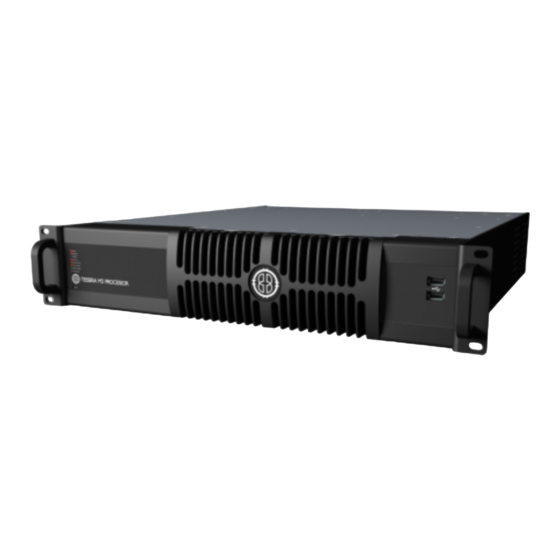
Page 16: Tessera T1 Led Processor
TESSERA T1 LED PROCESSOR FRONT PANEL Feature Description Front panel status LEDs Press to reset the processor, press and hold to restore to factory settings. Reset button Warning, this will delete all project files and fixture packs not included with the base firmware To connect USB memory storage devices and peripherals e.g. - Page 17 REAR PANEL CONNECTIONS Feature Description Connect a PC or Mac running the Tessera Remote, Tessera Control application or Management Ethernet an eDMX protocol directly to the local data Gigabit Ethernet port. The T1 processor can be operated locally with a monitor connected via Local User Interface DisplayPort.
-
Page 18: Chapter 3 - Quickstart
CHAPTER 3 - QUICKSTART Follow this chapter to get a basic system up and running. This guide covers starting a new project with fixtures connected. To set up a project offline and connect fixtures at a later stage, see “Tessera Management Software”... - Page 19 TESSERA PROJECT SETUP 1. From the Start Screen, select New to launch the Project Wizard. Figure 3-2. The New Project Wizard 2. The project name can be manually entered, if no entry is made, a default project name containing the processor’s model with a date and time stamp is assigned.
- Page 20 CONNECTING FIXTURES Figure 3-4. Add Fixtures from Network button 1. Ensure that all fixtures are connected to the processor with the desired topology, taking into consideration the output port’s capacity limit. 2. Click the Add Fixtures From Network button. The canvas toolbar is replaced with a row of currently connected fixtures.
- Page 21 6. Clicking and dragging will draw an array of fixtures. The topology is defined by the direction taken when drawing the array. 7. Repeat the process for all strings, then press Enter or click the Back arrow to return to the Main Project Screen.
-
Page 22: Chapter 4 - System Configuration
CHAPTER 4 - SYSTEM CONFIGURATION CONNECTING FIXTURES Tessera processors drive Tessera compatible devices. Tessera compatible fixtures are fitted with an Tessera receiver card inside, either in each tile or cabinet, or in a root node connected to strings of sub-fixtures. All Tessera compatible fixtures have two gigabit Ethernet ports: one to connect to the processor and one to connect to the next device in the chain. -
Page 23: Redundancy Configuration
Closed loop redundancy is supported on Tessera SX40, M2 and S4 LED processors where two outputs can be configured to operate as a redundant pair. Closed loop redundancy is not supported on Tessera T1 LED processors as they only feature a single output. - Page 24 Figure 4-2. Redundancy options on the Network tab for Tessera processors The Network tab includes the loop status indicator and a load bar for a redundant output pair on ports 1 and 2. Ports 3 and 4 continue to operate independently without redundancy. Note - The system load will double when redundancy is enabled, this is because twice the amount of bandwidth is needed to ensure primary and backup signals are maintained.
- Page 25 Figure 4-4. Tessera SX40 configured with redundancy for trunks A and B and C and D When operating in redundancy mode: Fixtures can be cabled in a single chain of up to 50 fixtures, with each end of the chain connected back to the processor (or Tessera XD when using a Tessera SX40).
- Page 26 PROCESSOR REDUNDANCY Only available for the Tessera SX40, processor redundancy is designed as a backup system should the primary processor fail to send a signal to the fixtures. If the primary processor stops outputting video signal, the backup processor will detect the fault and re-associate fixtures. Fixtures will lose video signal momentarily and will automatically resume within 1-2 seconds.
- Page 27 Figure 4-5. Processor redundancy Processor redundancy is compatible with closed loop redundancy, offering different setup possibilities based on the system requirements. Figure 4-6. Tessera SX40 LED processor and loop redundancy...
-
Page 28: Output Capacity
OUTPUT CAPACITY The Tessera output port capacity depends primarily on the network bit depth and frame rate. The nominal pixel capacity per port is outlined in the table below: Refresh/Bit Depth 8 bit 10 bit 12 bit 24hz 1,312,500 1,050,000 875,000 25hz 1,260,000... - Page 29 Mapping Mode For Projects With Multiple Fixtures The M2 and T1 processors can use different mapping modes to fit the project’s necessities. The SX40 and S4 always work with 1:1 mapping. 1:1 mapping doesn’t affect the output capacity. This mode sends the pixels of the input to the fixtures without taking into consideration the fixture size, only the pixel number.
-
Page 30: Combining Processors
COMBINING PROCESSORS The Tessera T1, S4, M2 and SX40 processors are designed to be used together in a configuration without issues. Different types of processors can be used to run different sections of the same wall. When combining processors, to avoid tearing, it is important to synchronize them by matching their end to end delay and genlocking the sources. -
Page 31: Chapter 5 - Tessera Management Software
The main difference in functionality when working with the Tessera Remote app (not offline) is that the video on canvas edit modes are not available. Tessera Remote is free to download from the Brompton Technology website: http://bromptontech.com/support Note - Tessera Remote software versions and the processor firmware versions must match. - Page 32 INSTALLATION FOR WINDOWS PC 1. Download Tessera Remote Windows software from https://www.bromptontech.com/support 2. Open the downloaded file to begin Setup Wizard. Hit Next to continue. 3. The setup wizard gives options to create shortcuts for your computer and whether to associate relevant files to the application.
- Page 33 4. The setup wizard asks for an install location, once selected click Next to begin the installation. 5. When the application has finished installing, a completion dialog box is displayed. Tick the ‘Run Tessera Remote’ box to launch the application after clicking Finish.
- Page 34 INSTALLATION FOR MAC OS X 1. Download Tessera Remote Mac OSX installation file from Brompton’s website https://www.bromptontech.com/support 2. Double click the .dmg file and drag the Tessera Remote icon into the Applications Folder, or copy (⌘ + C) and Paste (⌘ + V) the Tessera Remote icon into the Applications folder 3.
- Page 35 CONNECTING TO A TESSERA PROCESSOR Having physically connected a Mac or Windows PC to a Tessera processor via network, launch the Tessera Remote application. This will open a dialogue box to start Tessera Remote or the Offline Editor. Figure 5-1. Start up menu for Tessera Remote Click ‘Start Tessera Remote’...
- Page 36 IP address Project file that is currently in use To connect to the processor, double click the processor, or select a processor and click Connect. TESSERA REMOTE SETTINGS The Tessera Remote offline mode Settings menu contains preferences which allow general customisation of the canvas, fixture packs management and selection settings within Tessera Remote.
- Page 37 Disconnecting from the processor: Figure 5-5. Tessera Remote, disconnection from processor options. Clicking “Leave the project open on the processor” will return control to the processor’s local UI while keeping the project open. Clicking “Close the project on the processor” returns control to the processor’s local UI and closes the current project.
- Page 38 MULTIPLE PROCESSOR CONTROL There are different approaches to control multiple processors: Use a single Tessera Remote instance - It is easy to connect and disconnect from different processors on a network. The output from the processors will continue uninterrupted when Tessera Remote is not connected.
-
Page 39: Chapter 6 - Project Setup
CHAPTER 6 - PROJECT SETUP PROJECT MANAGEMENT OPENING AND IMPORTING PROJECTS Select a project from the list then click Open from the left menu. You can also import projects from USB drives or the local computer storage drive. Figure 6-1. Importing projects in the project management screen To import a project using the processor: 1. - Page 40 EXPORTING PROJECTS In the remote app, to export a project stored in the processor, select the desired project from the project management screen and click Export project to select the location. When a project is open, pressing Save as... is used to create a copy of the project and set it as the active project. Save a copy, creates and saves a copy of the project to the computer whilst keeping the current project open for editing.
- Page 41 To start a new project, select New on the project management screen. Once the New Project Wizard launches: 1. Enter a project name 2. Select a canvas size, Low Latency mode is automatically enabled on Tessera T1 and M2 LED processors if canvas sizes other than 1920x1080 are used.
- Page 42 2. Enter a project name and the location for the project file to be saved to. 3. Select a canvas size, Low Latency Mode is automatically enabled on Tessera T1 and M2 LED processors if canvas sizes other than 1920x1080 are used.
- Page 43 CANVAS RESOLUTIONS Tessera systems allow the source to send any input resolution that fits within the canvas size, except when working at 2880x720 or 720x2880 in the HD processors. Tessera M2/S4/T1 The native canvas size for processors is 1920x1080 pixels The following list of non-standard canvas sizes are allowed, but places the processor in Low Latency Mode.
- Page 44 Low Latency Mode reduces the overall latency by one frame. Tessera T1 and M2 LED processors work at a latency of 3 frames. In Low Latency Mode, the latency is reduced to 2 frames. Tessera S4 LED processors are always in Low Latency Mode, and non-standard canvas sizes automatically switch the Tessera M2 and T1 LED processors into Low Latency Mode.
- Page 45 Figure 6-6. Fixture output in 1:1 mode Figure 6-7. Fixture output in Interpolated mode PORT CAPACITY IN 1:1 OR INTERPOLATED When using 1:1 mapping, the output capacity is not affected. In interpolated mapping, the content on fixtures with a coarser pixel pitch is scaled to take the panel size into consideration, so that content appears the same size across all fixtures.
- Page 46 Type C: 15.6mm pitch, 1000mm x 500mm physical size, 64 x 32 = 2048 pixels Figure 6-8. Different pixel pitch fixtures Real Pixel Count Size (mm) Pixel Count Interpolated Pixel Count 1:1 10,000 500x500 10,000 10,000 4096 500x500 10,000 4096 2048 1000x500 20,000...
-
Page 47: Chapter 7 - Fixtures
CHAPTER 7 - FIXTURES FIXTURE LIBRARIES To correctly communicate with fixtures, the processor needs to have the fixture firmware included in the fixture library. A fixture pack is installed with every version of the processor’s firmware and updated fixture packs can be found on our website. See “Fixture Library”... - Page 48 PER-FIXTURE AND PER-GROUP COLOUR OVERRIDE Figure 7-2. Global Colour Override options in Colour property editor Single fixtures or groups of fixtures can be made exempt from Global Colour control and assigned separate values. This is useful to maintain one screen at a constant brightness when other fixtures are grouped into separate screens on a processor.
- Page 49 DEVICE PROPERTIES The device property editor shows information stored on the R2 receiver card. FIXTURE QUICK ACCESS BUTTONS In the title bar for the Device property editor, there are three quick access buttons: Reset: Reboots the fixture, video will stop displaying in the following devices connected in the same string, as data is not passed through while the fixture is rebooting.
- Page 50 Figure 7-4. Internal Test Pattern drop-down menu Although fixture models vary, most fixtures have a self-test button on the back of the fixture which can be used to activate test patterns by holding on the button for 4 seconds. (Refer to fixture manufacturer documentation for specific functionality).
- Page 51 OSD or On-Screen Display is supported on R2-based fixtures and offers the possibility to display information on the fixture itself, the processor or the project. Note - OSD is supported on rectangular fixtures with a minimum size of 64x64 pixels but no larger than 1024 pixels in either dimension and up to 262,000 pixels (e.g.
- Page 52 STUDIO MODE Studio Mode reduces a fixture's maximum brightness while maintaining the PWM bit depth, thereby resulting in improved image quality (with less banding) when running at low brightness. The maximum benefit is seen on particularly bright fixtures, especially those running at relatively low PWM bit depth (14 bit or below). See Studio mode on page for more information.
- Page 53 FIXTURE CONTEXT MENU Right-click a fixture to open a context menu with a list of options. These options are grouped by type and some options have keyboard shortcuts displayed on the right side column. If a fixture is un-associated, some options are unavailable.
-
Page 54: Adding Fixtures To A Project
ADDING FIXTURES TO A PROJECT There are two main workflows for adding fixtures to a project. With fixtures connected to the processor. The project and fixture layout are created on a processor with fixtures physically connected. In this case use Add Fixtures from Network Without fixtures connected to the processor (or in offline mode). - Page 55 When associating by selecting ports for each string, the string is represented by a unique colour in the user interface and physical fixtures. Fixtures illuminate corresponding to identified strings. The Tessera T1 LED processor only has a single output port so there is no port selection and only displays available strings of fixtures.
- Page 56 Rotation Fixtures can be rotated before being placed on the canvas. Use the Rotation slider on the Draw Array property editor or alternatively use Alt + mouse wheel to modify the rotation angle. Figure 7-12. Draw array feature for rotating fixtures before placing Array types To place an array of fixtures, hold the left mouse button while placing the fixture.
- Page 57 Grid arrays The Grid Add Fixtures property editor contains options for the user to adjust position, change grid size, define spacing between fixtures or rotate to a desired location. Figure 7-13. Grid fixture layout property editor...
- Page 58 Circle arrays The Circle Add Fixtures property editor contains options for the user to place fixtures in a circular array. The radius, position, rotation and fixture count can be changed. Figure 7-14. Circle fixture layout property editor Radial Arrays Differs to the circle option by offering the option to place multiple fixtures in a circle, spanning outwards to create a wider display.
- Page 59 ADD FIXTURES FROM LIBRARY It is possible to work offline and create a layout when fixtures are not connected either by using the Tessera Offline Editor in Tessera Remote, or by using the local user interface. In each case the user will need to add fixtures from the library, as no fixtures are connected so Add Fixtures From Network will be disabled.
-
Page 60: Sub-Fixtures
SUB-FIXTURES Sub-fixtures do not have a Tessera interface and so cannot be connected directly to a Processor or XD output. Instead multiple fixtures are connected to a single power/control box. These fixtures are represented in the Tessera system as sub-fixtures. The power/control boxes are called root nodes. Each root node contains a R2 receiver card, and like normal panel-type fixtures are connected to the rest of the system over daisy-chained Gigabit Ethernet. - Page 61 ROOT NODES PROPERTIES Figure 7-18. Device property editor The device property editor shows the information of the R2 receiver card and the root node. Device Information The first section lists the MAC Address, serial number and firmware version information of the R2 receiver card. Note - OSD is not available for sub-fixtures.
- Page 62 Sensors Information Information such as Temperature or Humidity is displayed if the root node has the appropriate sensors. SUB-FIXTURES CONTEXT MENU Right-click the root node to open a context menu with a list of options. Sub-fixture options are the same as other fixture’s options.
- Page 63 Figure 7-21. Notification to configure root nodes not matching fixture topology CONFIGURING THE ROOT NODES ONLINE Using Add Fixtures from Network . The root nodes need to be connected to the processor and online. 1. Click Add Fixtures from Library or Add Fixtures from Network 2.
- Page 64 OFFLINE Using Add Fixtures from Library 1. Click Add Fixtures from Library. 2. Select the root nodes and place on the canvas. The search bar can be used to filter fixtures. Figure 7-24. Adding a Root node to canvas 3. Press Tab to start associating sub-fixtures. Repeated presses of Tab or the Next Port button advances through the ports.
- Page 65 6. Select the port connected to the root node for association. 7. Draw the sub-fixtures of the selected port on the canvas and continue to other connected ports. 8. Press escape to got to the previous menu or enter to finish association and return to Canvas view. If the configuration is correct, all sub-fixtures are now ready for use.
- Page 66 Figure 7-27. Context menu to correct association once a fixture on canvas is discovered SUB-FIXTURE INTERNAL TEST PATTERNS Test patterns can be enabled on sub-fixtures from the fixture properties editor. Different patterns can be enabled on each sub-fixture. If test patterns are enabled on one sub-fixture, all other sub-fixtures on that root node will cease to display live video.
-
Page 67: Understanding Topology And Association
UNDERSTANDING TOPOLOGY AND ASSOCIATION Tessera processors can detect the topology of connected fixtures. Topology is the order which fixtures are connected, which port on the processor they are connected to and if fixtures are broken into strings by switches. The topology tools are used to help users associate physical fixtures with fixtures on the canvas. Fixtures are identified by a unique MAC address. - Page 68 CHANGING PHYSICAL TOPOLOGY If the fixtures’ topology is modified, for example to balance the ports load, the fixtures are automatically re- associated. Example: The fixtures in a wall are associated to the processor in a topology using ports 1 and 2 as shown below: Figure 7-30.
- Page 69 Figure 7-31. Fixtures with topology changed to balance laod on ports The processor automatically recognizes the fixtures MAC addresses and re-associates this fixture in the project. To see the topology errors, enable Show Topology Errors in the canvas view. The fixtures automatically begin functioning at this stage.
- Page 70 Figure 7-34. First topology The second time the fixtures are connected, the cabling topology is changed, as shown below. Figure 7-35. Second topology...
- Page 71 To correct the screen, use the following steps: 1. On the canvas select all fixtures with the incorrect topology. Right-click the fixtures and select Disassociate. 2. Click Edit Topology to view the Topology toolbar and select the string of fixtures requiring correction by double-clicking on the dot in the centre of a fixture.
- Page 72 Figure 7-38. Completed topology string 7. Once corrections are complete, return to the main project view by pressing Esc or clicking on the arrow located at the top left of the interface . The processor detects a new topology which doesn’t match the current association and displays the Correct Association message for 10 seconds.
-
Page 73: Fixture Layout
FIXTURE LAYOUT SELECTING INDIVIDUAL FIXTURES Click to select a fixture.The fixture will turn blue and the Fixture property editor will be displayed on the right side of the user interface. See “Fixture Properties” on page for more information. Right-click on a fixture to display a context menu. - Page 74 Figure 7-41. Group properties Group The group property editor is divided in three sections. Group info Name: Change the name of the group. To see the name in the canvas, activate Show Group Names in the View dropdown menu or in the Canvas context menu.
- Page 75 Colour Colour modifications can be enabled in the selected fixture independently from the Global Colour. When the Override Global Colour box is ticked, colour modifications for the selected fixture are enabled and Global Colour property editor values do not have an effect on the fixture. GROUP CONTEXT MENU Right-click in a group to open a context menu with a list of options.
- Page 76 ROTATING FIXTURES Fixtures can be rotated by 90-degree increments on all processors, however Tessera M2 and T1 LED processors support free rotation, allowing rotation to any degree at a cost of doubling the bandwidth required to drive the fixtures. Figure 7-43. Network load is increased when rotating fixtures by 90 degrees Fixtures can be individually rotated around their top-left corners by first selecting the fixture, then either click the rotation icon in the toolbar or right-clicking and selecting Rotate Selection.
- Page 77 Figure 7-44. Manually rotate a fixture using the anchor handle Alternatively press Ctrl+Shift+R or select from the Edit property editor to enter rotation mode. Fixtures can also be rotated during association by pressing the Alt key and using the mouse wheel to change the rotation angle.
-
Page 78: Chapter 8 - Main Project Screen
CHAPTER 8 - MAIN PROJECT SCREEN When creating a new project, the Main Project Screen opens with multiple view modes: Canvas view: Allows layout editing and visualization of fixture position on the selected canvas, topologies, video source and access to the tools for image adjustment in the LED devices, and troubleshooting. - Page 79 CANVAS PROPERTIES The canvas properties editor can be accessed by selecting Properties in the canvas properties toolbar, on the top-right of the canvas. Figure 8-2. Canvas properties Size The canvas size can be freely modified however the input source must fit within the width and height dimensions.
- Page 80 Scale If the image size differs to the canvas size or to the desired size, the size can be modified by selecting a pixel ratio. When the selected units are pixels, a 1px value will show the real size of the image, values lower than 1px reduces the image size while values above increase its size.
- Page 81 CANVAS CONTEXT MENU Right-click an unused area of the canvas to open a context menu with a list of options to customize the appearance and usability of the canvas. Figure 8-3. Context menu when right-clicking unused area on canvas Function Description Paste Paste the previously copied fixture to this place on the canvas.
- Page 82 CANVAS TOOLBAR The Main Toolbar offers a selection of tools to draw fixtures on the canvas and select zoom and view positions. Figure 8-4. Canvas toolbar features Icon Icon Description Description Undo and redo the last action performed. The shortcut commands for Undo/Redo arrows Undo are Ctrl+Z (⌘...
- Page 83 CANVAS EDIT VIEWS EDIT MODE Edit Mode views allow fixtures to be positioned on the canvas. Edit Mode: Keyboard Shortcut: F1 Edit Mode is the default mode for the canvas and allows fixture positioning. In Edit mode the fixtures are displayed as viewed from the front.
- Page 84 VIDEO ON CANVAS MODE The Video on Canvas Mode view displays the currently selected video input onto the Canvas, including Viewport and Active Area settings. This mode shows how input content is displayed on fixtures in real-time. Note - Video on Canvas mode is not available on Tessera S4 processor or accessible using Tessera Remote.
- Page 85 Video And Fixture Mode: Keyboard Shortcut: F4 Video and Fixture Mode displays the current video input on both the fixtures and the canvas. The video within the Active Area that is not being displayed on the fixtures is shown greyed out as shown in the picture below. Video Only Mode Keyboard Shortcut: F5 Video Only Mode displays the current video input within the Active Area on the canvas without displaying the...
- Page 86 HEAT MAP Keyboard Shortcut F6 Selecting 'Heat Map' from the canvas display mode button (or pressing F6) displays fixtures on the canvas coloured based on the temperature reported by internal sensors. The fixtures display a colour representing the temperature. Temperatures ranging from the coolest fixtures (black) to the hottest fixtures (white).
- Page 87 Fixtures can be assigned to layers which have a Z-order. Z-order refers to the front to back ordering. Layers are particularly useful when two groups of fixtures are superimposed on the canvas, so that the content can be easily duplicated on two sets of fixtures, such as when using two screens showing the same content on either side of the stage.
- Page 88 Stack Property Editor Widgets A selection of property editor widgets can be arranged to be displayed simultaneously. Press and hold the CTRL button while clicking in the desired Pipeline tiles to see how the Property editors get added on the Properties area.
- Page 89 PIPELINE The pipeline represents the signal flow through the processor. The pipeline is composed of tiles arranged in groups. Working With Pipeline Tiles Activating Settings A white bar on the pipeline tile appears when settings are active. Double-click the pipeline tile to switch settings on or off.
-
Page 90: Presets
PRESETS At the bottom of the Main Project Screen, presets can be set to store settings on the processor. Presets can be made to affect all fixtures, a selection of fixtures or groups. The video source modifications affects all fixtures on the canvas. - Page 91 USING MASKING Figure 8-8. Preset Recording view Masking is useful for security when changing fixture position without altering colour information or to change the input source without affecting the global colour. When a preset is stored, three icons are displayed. The icons represent information that will be stored within the preset.
- Page 92 6. Only selected groups are stored into a Position preset. Once selected, the diagonal lines on the groups change to solid colour. If no group is selected, the following warning is shown. 7. Click an empty preset tile to store the new preset. 8.
- Page 93 Note - Other values like Colour and Position are not affected by the fade times and are committed as soon as the preset is activated. Crossfade only affects the source selection. Crossfading between inputs can be achieved by storing the different inputs as presets with a fade time. To store presets to crossfade from one input to another follow these steps: 1.
-
Page 94: Log
Information about the processes and errors that occur within the processor can be viewed by clicking on Log. This information can be stored in a USB drive or on the computer using the button Save the Log... -
Page 95: Moving Around The Canvas
MOVING AROUND THE CANVAS Move Controls Vertical scrollbar Arrow keys Page up/down keys Up, down, left and right Mouse wheel Horizontal scrollbar Arrow keys Shift + mouse wheel in the main toolbar Ctrl + mouse wheel Zoom in and out Ctrl + + to zoom in, Ctrl + - to zoom out Zoom to fit, Zoom 1:1 or Zoom to selection options Drag the canvas... -
Page 96: Project Data Export
PROJECT DATA EXPORT Tessera software has three types of files that can be exported: Canvas image, device layout and discovered devices. EXPORT CANVAS IMAGE To export an image, navigate to Tools and select Export Canvas Image. Several options are displayed for the user to choose and control how exported images are rendered. -
Page 97: Online View
ONLINE VIEW The Online Fixtures view provides comprehensive information about all fixtures currently detected by the processors output ports. EXPORTING ONLINE FIXTURE DATA To export information regarding connected fixtures, navigate to either the Tools drop-down menu or the Online view and click the Export Discovered Devices button. For more information see: Project Data Export page NETWORK ERROR MONITORING... - Page 98 Error counters update every couple of seconds, which helps to correlate errors with intermittent external events that might cause data corruption (such as using radios or the switching of high-power loads nearby). In this case, either remove or relocate the source of the interference, or consider using shielded data cables. Note - Standard precautions must be taken if using shielded cables, as this can electrically connect the two device’s earthing.
-
Page 99: Topology View
TOPOLOGY VIEW The Topology View is exclusive to Tessera SX40 LED processors. Topology view shows the current network topology of the processor, connected XD units and fixtures. On the left, the letters A, B, C, & D represent the physical ports of the Tessera SX40. Green arrows represent a connection between the processor ports to any connected XD distribution units and their ports. -
Page 100: Chapter 9 - Inputs
CHAPTER 9 - INPUTS HD SOURCES (FOR M2, T1, S4) Figure 9-1. Input Sources for Tessera SX40 3G SDI INPUT (M2 ONLY) Each SDI input on the Tessera M2 LED processor provides support for: 3G-SDI Level A 3G-SDI Level B Dual-Link (Level B Dual-Stream is not supported) HD-SDI SD-SDI Standard broadcast resolutions up to 1920x1080 are supported, with framerates between 23.98Hz to 60Hz... - Page 101 4K SOURCES (FOR SX40) 12G SDI INPUT The Tessera SX40 processor provides support for: 12G-SDI 2S (SQ is not supported) 6G-SDI 3G-SDI Level A 3G-SDI Level B Dual-Link (Level B Dual-Stream is not supported HD-SDI Standard broadcast resolutions up to 4096x2160 are supported, with framerates between 23.98Hz to 60Hz and fractional frame rates such as 59.94Hz and 23.98Hz.
- Page 102 Figure 9-2. Source preview thumbnails displayed on the pipeline tiles When selecting an input, its indicator will change from black to white. The quickest way to change inputs is to double-click the input source pipeline tile. Some processors only have a single input, so source selecting is not available.
-
Page 103: Input Colour Control
INPUT COLOUR CONTROL BLACK LEVEL The black level control affects the base level brightness of the darkest content for the incoming feed. Modifying this value will affect the signal gradually but will be most pronounced at the lower end of the video signal nearest black. -
Page 104: Histograms
HISTOGRAMS Tessera LED processors offer a selection of histograms to depict distribution of pixels across the possible range of a colour or colours of the incoming video feed in real time after they have been modified by the input colour controls. - Page 105 SETTING COLOUR CONTROLS WITH THE AID OF HISTOGRAMS Histograms are useful for determining if an incoming signal is filling the entire spectrum of colour and brightness. Note - When choosing an image to balance, use an image from live event content throughout the project, an image with a wide variety of colours and hues, or a suitable test pattern.
- Page 106 Figure 9-6. Adjusting the black level control will make the blacks look darker and the concentrations of colour now reach down to 0% on the scale...
- Page 107 Figure 9-7. Adjusting the contrast control will make brighter areas appear closer to the 100% threshold, assuming some areas contain white content in the image and is desirable If specific colours do not render correctly, adjust RGB Highlight and Shadow controls to work on that specific colour without affecting the other two primaries.
-
Page 108: Chapter 10 - Processing
CHAPTER 10 - PROCESSING Figure 10-1. Processing pipeline tiles, featuring scaling and Chromatune features, colour replace anf 14 way colour correction SCALING AND CROPPING The Tessera M2 and T1 LED processors support scaling and cropping of the incoming feed. The Tessera SX40 processor supports scaling. - Page 109 Figure 10-3. Scaler zoom mode options 1:1 MODE The 1:1 mode selects and crops an area of the input maintaining the original Viewport image size. Dimensions Left: Determine the column of pixels that will appear on the left of the canvas Top: Determine the row of pixels that will appear on the top of the canvas Width: Determine the total width of the source (Maximum width will be the canvas width minus the Left value)
- Page 110 FIT MODE The Fit mode selects a section of the input and scales it to fit within the active area while maintaining the aspect ratio. Dimensions Left: Determine the column of pixels that will appear on the left of the canvas Top: Determine the row of pixels that will appear on the top of the canvas Width: Determine the total width of the source before being stretched (maximum width will be the canvas width minus the Left value)
- Page 111 FILL MODE The Fill mode selects a section of the input and scales it to fill the active area while maintaining the aspect ratio. Dimensions Left: Determine the column of pixels that will appear on the left of the canvas Top: Determine the row of pixels that will appear on the top of the canvas Width: Determine the total width of the source before being stretched (maximum width will be the canvas width minus the Left value)
- Page 112 STRETCH MODE The Stretch mode selects a section of the input and stretches it to fill the active area and match its width and height. Dimensions Left: Determine the column of pixels that will appear on the left of the canvas Top: Determine the row of pixels that will appear on the top of the canvas Width: Determine the total width of the source before being stretched (maximum width will be the canvas width minus the Left value)
-
Page 113: Active Area
ACTIVE AREA On the canvas, the Active Area is indicated by the grey mask with a dashed border. Figure 10-8. The canvas with the Active Area shown by a dashed border Having determined the region of interest to be captured from the incoming feed using the Viewport, that region can then be sized or moved as desired. - Page 114 ASPECT RATIO The Aspect Ratio value will force the dimensions into a standard ratio (4:3 or 16:9). Select “Free” to allow flexible modifications of the content. Dimensions Left: Determine the position of the left edge of the active area Top: Determine the position of the top edge of the active area Width: Determine the final width of the active area Height: Determine the final height of the active area To scale the content, set the Active Area dimensions to values greater or smaller than the Viewport.
- Page 115 SNAP TO SELECTION Adjust the active area size to match the size of the selection of fixtures. To resize the input source to fit all visible fixtures, select the chosen fixtures and click the Snap to Selection button. Figure 10-11. Active area scaled to snap to fixture selection SNAP TO CANVAS Adjust the active area size to match the canvas size.
-
Page 116: Chromatune
CHROMATUNE Figure 10-13. ChromaTune pipeline tiles, colour replace and 14 way colour correction ChromaTune consists of two advanced colour correction features. One is Colour Replace, which gives the user advanced control to manipulate one specific colour with flexibility. The other is 14-way Colour Correction which enables adjusting one or a number of pre-defined colours by modifying their Hue, Saturation or Brightness. - Page 117 Figure 10-15. Selecting a colour from the colour picker. Colour Tolerance: Determines the Hue range that is affected by the modifications. Brightness Tolerance: Determines the Brightness range that is affected by the modifications. Apply to Hue, Apply to Saturation, Apply to Brightness: These checkboxes apply the tolerance settings to their respective parameters.
- Page 118 COLOUR REPLACE EXAMPLES A red pepper can be changed into green pepper easily. Here is the original red pepper image: Figure 10-17. Original red pepper Select a red colour from the from the canvas using the eyedropper tool, and a suitable green from the colour picker: Figure 10-18.
- Page 119 To turn the pepper completely green requires some adjustment, in this case increasing the Hue Tolerance parameter to 25%, as seen in the image below: Figure 10-20. The resulting green pepper after increasing the Hue Tolerance It is recommended to use the View Matte feature when using Colour Replace, as this shows the areas of the image that will be affected by the colour replace operation.
- Page 120 14-WAY COLOUR CORRECT Figure 10-22. 14 way colour correct pipeline tile with all colours adjusted The 14-way Colour Correct feature allows singular or multiple pre-defined colours to be adjusted without affecting other colours. Hue, saturation and brightness controls are provided for each of the primary, secondary and tertiary colours.
-
Page 121: Chapter 11 - Test Patterns
CHAPTER 11 - TEST PATTERNS Figure 11-1. Test Pattern Pipeline tile in deactivated state PROCESSOR TEST PATTERNS All Tessera LED processors have a selection of test patterns that can be used to check the performance of fixtures and verify that a fixture layout is correct. Scrolling test patterns will always move exactly one pixel horizontally and/or vertically, therefore motion should be perfectly smooth. - Page 122 Figure 11-3. Test Pattern pipeline tile, indicating the current active test pattern CUSTOM TEST PATTERNS The Custom Test Patterns section allows for custom images to be loaded into the processor or captured from the video input. Figure 11-4. Custom Test Pattern Options To use a custom test pattern, select the Pattern pipeline tile under Override in Canvas View.
- Page 123 FIXTURE TEST PATTERNS In addition to processor test patterns, individual fixtures also contain a set of pre-programmed test patterns. Individual or groups of fixtures can display patterns by selecting them in Canvas View. See "Device Properties" on page for more information. FREEZE/BLACKOUT Double-clicking the Freeze pipeline tile or pressing the physical Freeze button on the processor will pause the incoming video signal and hold the final frame indefinitely.
- Page 124 If needed, failover can also be triggered by pressing both buttons at the same time when Tessera SX40 is cabled for Processor redundancy. This can be enabled or disabled in the Failover property editor. Figure 11-8. 7 Check box to enable failover when both physical buttons on processor are pressed The front panel buttons can be disabled by unchecking the Enable Buttons checkbox.
-
Page 125: Chapter 12 - Global Colour
CHAPTER 12 - GLOBAL COLOUR The following controls are available in the Global Colour pipeline tile and apply to all fixtures in a project unless those fixtures (or groups) have been overridden. See "Per-fixture and Per-group Colour Override" on page for more information. - Page 126 Where more than one type of fixture with different maximum brightness values is used, the slider has no effect on a fixture's brightness once its maximum value is exceeded. The brightness slider will default using the brightest value that all the fixtures in a project can reach. Example: If a project consists of two different types of fixtures, one of which has a maximum output of 5000 Nits and another has a maximum brightness of 2000 Nits, the default value of the brightness slider will be 2000 Nits.
-
Page 127: Dark Magic
DARK MAGIC LED panels are often run at a lower brightness than their maximum capability, e.g. for indoor and 'on-camera' applications. This results in an unavoidable reduction in effective bit depth, which can lead to visible artefacts such as banding and loss of detail, especially in dark areas of the image. Enabling Dark Magic will increase the visual quality of the output when operating at low brightness. - Page 128 Figure 12-4. Dark Magic disabled with visible banding, compared with enabled...
-
Page 129: Low End Boost
LOW END BOOST As Gamma control adjusts the mid-tones of video content, Low End Boost adjusts the brightness of darker video content areas. For accurate reproduction, this control is recommended to remain at 0%, but in some cases a higher setting can recover detail in dark areas of the content. Excessive levels of Low End Boost may start to reveal limitations in the content such as compression artefacts and camera noise that normally would remain hidden. -
Page 130: Studio Mode
STUDIO MODE Studio Mode is a feature specially designed for Tessera fixtures. Studio Mode reduces panel brightness while maintaining the PWM bit depth, resulting in improved image quality and reducing banding when running at low brightness. The maximum benefit is seen on particularly bright panels, especially those running at relatively low PWM bit depth. -
Page 131: On-Screen Colour Adjustment
ON-SCREEN COLOUR ADJUSTMENT Tessera LED processors feature a comprehensive fixture-based seam adjustment for fixture and module seams, and 7-way colour correction for modules and panels. OSCA is an abbreviation for On-Screen Colour Adjustment. When in OSCA Mode, the OSCA interface appears on the output fixtures themselves, showing the mouse position and highlighting selected seams, fixtures or modules for quick and intuitive adjustments. - Page 132 Figure 12-9. The On-Screen Colour Adjustment window The On-Screen Colour Adjustment window displays the fixtures in the project as they are positioned on the canvas. The mouse can select fixtures or seams and using the keyboard arrow keys will change the selected object.
- Page 133 Figure 12-11. The Display Colour section of the OSCA toolbar Adjustments can be made to white, primary and secondary colours. When in colour correction mode, the controls only adjust the Master colour of the fixtures and/or the colour of the test pattern being used BRIGHTNESS SLIDER OSCA adjustments are performed in the On-Screen Colour Adjustment window.
- Page 134 Button Function Shortcut key All modules seams selection Modules horizontal seams selection Modules vertical seams selection Panel all seams selection Panel horizontal seams selection Panel vertical seams selection Multiple seams can be selected by using Ctrl+click or click and drag the left mouse button to create a selection box around the seams.
- Page 135 Figure 12-14. OSCA on fixtures showing selected seams and cursor Once seams have been selected, luminance can be adjusted by: 1. Pressing and holding the 1 key and use either the + and – keys or the up and down arrows on the keyboard to increase or decrease luminance.
- Page 136 Figure 12-15. Seam Brightness Correction property editor, displaying luminance thumbwheel The Seam Brightness Control panel features a Layers selection. Currently displayed layers are checked, to 'hide' layers, uncheck the corresponding check-box. Hidden layers do not output whilst in OSCA Mode. See "Layers" on page for more information.
- Page 137 To adjust colour for selected modules, select the Module icon or press F7. For fixtures, press F8 or select the Fixture icon on the OSCA toolbar. Figure 12-16. Icons for selecting module or fixture Colour Adjustment on the OSCA toolbar The following figures show a selection of fixtures or modules respectively: Figure 12-17.
- Page 138 Figure 12-18. The canvas in fixture selection mode for Colour Adjustment Once modules or fixtures colour correction is selected, the Colour Adjustment panel is shown. The properties can be adjusted: 1. Press hold the shortcut key and use in conjunction with the + and - keys or the up and down arrows to increase and decrease values.
- Page 139 Figure 12-19. Yellow Adjustments Hide adjustments: When adjustments are being made, the selection is hidden for a better view of the modifications. Disable this option to keep the selection always active. Fine controls: Enabling Fine controls gives the user the finest amount of control, a single key press adjusts to give the smallest change possible compared to the default mode where changes are substantial.
- Page 140 Figure 12-20. The Colour Adjustment panel showing Master Colour Reset: If needed, the modifications values of each parameter can be reset in the selected modules using the reset button. To delete all the modifications done to the selected modules, press the Reset All Selected Modules option located below the adjustments thumbwheels.
- Page 141 COPYING AND PASTING OSCA SETTINGS Copy: OSCA settings can only be copied from a single module, copying from multiple modules is not supported. In OSCA mode, select a single module, right-click and select Copy OSCA colour settings. Paste: Settings can be pasted to single or multiple modules simultaneously. 1.
- Page 142 Function Shortcut Key Increase/decrease parameter Click+Scroll Wheel Saturation Luminance Decrease parameter Increase parameter Fine Adjustment Ctrl+parameter shortcut White Adjustment Function Shortcut Key Luminance Adjustment Red Gain Green Gain Blue Gain Red, Green, Blue, Cyan, Magenta And Yellow Adjustment Function Shortcut Key Red Gain Green Gain Blue Gain...
-
Page 143: Chapter 13 - Network
CHAPTER 13 - NETWORK NETWORK LOAD The Network Property Editor displays the network load on each Tessera output. The greater the network load, the further the green bar fills. The processor will issue a warning once an output is overloaded. If this happens the bar will turn red, consider moving fixtures to other outputs or decrease the network bit depth. - Page 144 NETWORK BIT DEPTH Figure 13-2. The Network Bit Depth drop-down menu Network bit depth refers to the bit depth at which video data is encapsulated, packetized and sent to connected fixtures. Front-side processing is always 12 bit and is unrelated to Network bit depth. Processing bit depth is always 16 bit and is also unrelated to Network bit depth.
- Page 145 Note - The selected genlock frame rate affects the capacity of each Tessera output port. See "Output Capacity" on page for more information. If the frame rate of the video input differs from the reference, whether it is internal, another video input or a bi-level or tri-level sync, the processor will match the frame rate by either doubling or dropping frames.
-
Page 146: Chapter 14 - Live Control
CHAPTER 14 - LIVE CONTROL Figure 14-1. Live Control pipeline tile Live Control allows users to control and modify the colour, video and position parameters of the processor remotely using the industry standard DMX, Art-Net or sACN protocols or using the Tessera Control application available for Windows and Mac OS. - Page 147 Note - If the DMX or eDMX signal is lost, changes will remain for as long as the Live Control pipeline tile is enabled. The Live Control pipeline tile indicates the six different states. Pipeline Tile Status Description The Offline tile appears in Tessera Remote offline projects. This indicates that there is no processor connected and is therefore Offline offline.
- Page 148 Figure 14-3. Control profile configured with Live Control active When it is disabled, the dot next to the controlled parameters will show only the white border. Their values will be enabled for manual adjustments. Figure 14-4. Control profile configured, and Live Control disabled CONTROL PROFILES Tessera Processors contain a selection of control profiles with various parameters for DMX, Art-Net and sACN modes only.
- Page 149 Figure 14-5. Live Control property editor, displaying Control Profile options Control Profile Parameters (510 Channels total if fully assigned) 170 RGB Groups 170x Group assignable sets of Red, Green, Blue (28 Channels total if fully assigned) Colour 1x Global control of Red, Green, Blue and Intensity Gain 6x Group assignable sets of Red, Green, Blue and Intensity Gain controls (512 Channels total if fully assigned) Colour 127 Groups...
- Page 150 ASSIGN CONTROLS TO A GROUP OR INPUT Some Control Profiles contain multiple sets of group or input controls that allow users to assign each set of controls to a single group (of fixtures) or input (DVI, SDI or HDMI). This control is in the form of a drop-down menu for each set in the Channel column. When a new profile is selected, all user assignable sets will have the legend “No assigned group”...
- Page 151 Figure 14-7. Configuring Fixture Groups In the illustration above, the project includes 4 fixture groups. The user can assign each screen to a set of DMX channels and parameters that are controllable by their DMX, Art Net or sACN control device. FOR INPUT CONTROL In some profiles, the legend will reveal a drop-down menu for the video input selection.
- Page 152 MINIMUM AND MAXIMUM VALUES Minimum and maximum values contained within control profiles parameters set the range of values achievable when controlled with live control. The parameter will be limited between the minimum and maximum values, with the DMX channel used to control the parameter being scaled between the two values. This is useful in situations where it is important to limit the lowest or highest values of a parameter.
-
Page 153: Dmx Control
DMX CONTROL CONFIGURING THE PROCESSOR FOR DMX CONTROL 1. Connect a source of DMX512 to the opto-isolated XLR 5 pin input. 2. Go to the Live Control pipeline tile and select DMX from the Control Protocol drop down menu. 3. Enter a Start Address for the processor. The Start Address will correspond with the DMX address of the first parameter in the selected Control Profile. -
Page 154: Edmx Control
EDMX CONTROL CONFIGURING THE PROCESSOR FOR EDMX CONTROL Both Art-Net and sACN (Streaming ACN aka E1.31) are supported. 1. Connect an eDMX source to the Net port on the processor’s back panel (either directly or via switch). 2. Go to the Live Control pipeline tile and select Art-Net or sACN from the Control Protocol drop down menu. -
Page 155: Tessera Control
TESSERA CONTROL Figure 14-9. Control application GUI 1. Download and install the Tessera Control application on a Windows or Mac computer. 2. Run the application and select the relevant Network Interface from the drop-down. 3. Connect the computer to the Net port on the processor’s back panel (either directly or via switch). 4. -
Page 156: Chapter 15 - Processor Settings
CHAPTER 15 - PROCESSOR SETTINGS Access settings from the menu on the left of the Project Management Screen. Figure 15-1. Project Management screen, select Settings from the left menu If a project is open, choose Settings from the Tools menu of the Main Project Screen. PROCESSOR Figure 15-2. - Page 157 Note - For any changes applied, the commit button needs to be clicked to save the modifications. IDENTIFICATION The name of the processor can be changed on the processor or when connecting to it remotely. This is useful when building a system that uses multiple processors. If no Processor name is defined, the processor will display its serial number in the Discovered Processors list in Tessera Remote and in the Remote windows title bar, for recognition when using several instances of the Tessera Remote.
- Page 158 Note - This option doesn’t affect the video input or output of the project. Enable Watchdog The watchdog is a hardware level process separated from the main processor which monitors and restarts if the processor stops responding, or in the event of a complete processor crash. If watchdog is disabled, the processor will remain in this state until it is manually rebooted.
- Page 159 Figure 15-5. Processor settings when not connected to a processor using Tessera Remote...
-
Page 160: Security
SECURITY A password can be applied to the processor. Each time a user connects to the processor via Tessera Remote application they will be prompted to enter the password. The password will be reset if factory settings are restored or it can be removed by re-entering the password in this window. Figure 15-6. -
Page 161: Date And Time
DATE AND TIME A date and time can be applied to the processor, click on each value and use the keyboard to make modifications. Figure 15-8. Tessera Processor Date and Time settings Note - The date and time are also used in log files and crash reports. -
Page 162: Fixture Library
In situations where a new fixture type becomes available or when an urgent fix is required for an existing fixture, Brompton may release a Tessera Fixture Pack (.tfp file) containing the updated list of fixture firmware. The list of fixture personalities and its firmware version loaded into the processor is detailed in the Fixture Library. - Page 163 Figure 15-10. All fixture firmware contained in a fixture pack is shown in Manage Packs The new priority will take effect immediately for selected fixture firmware versions and the project will ask to update the firmware in the fixtures with the error “XX detected devices are not running the specified firmware version”.
- Page 164 OVERRIDE PRIORITY The priority order can be overridden so a selected fixture can use the firmware from a different fixture pack than the one with the highest priority. To change priority, select a pack then click Move Up or Move Down. Fixture packs at the top has priority over packs below.
- Page 165 PROJECT FIXTURES To display only the fixtures being used in the project that is open, check the tick box Hide unused fixture types. Figure 15-13. Filtering the fixture library to only show fixtures used within the current project. TRANSFERRING PACKS Fixture packs can be transferred between processors using the Export option.
- Page 166 ADDING AND REMOVING PACKS To import a new fixture pack, click Manage Packs and click Add. Select the location where the pack is stored. Select the fixture pack and press open to load it into the processor. Figure 15-14. Adding a fixture pack To remove a pack, first select it from the list then click Remove.
-
Page 167: Preferences
PREFERENCES Figure 15-15. Preferences menu GENERAL The status bar is located on the bottom of the Project Canvas. It provides helpful tips and information of where the mouse cursor is located. Unticking the option in the preferences menu hides the bar. Figure 15-16. - Page 168 Selection Mode Selection modes alter the behaviour for dragging a selection box around fixtures on Canvas View. To change Selection Mode, navigate to Settings > Preferences. Inside selection area The selection area must completely enclose fixtures to select them. Overlaps selection area A fixture will be selected if any part of the fixture is within the selection area.
-
Page 169: Crash Management
CRASH MANAGEMENT Figure 15-18. Crash Management options in Processor Settings The processor will pause after a crash before rebooting to allow time for the user to enter information about what actions were performed before the crash. The time duration of this pause can be set to unlimited or between 0 and 3600 seconds. -
Page 170: Restore Factory Settings
RESTORE FACTORY SETTINGS Figure 15-19. Restore factory settings, with warning prompt before restoring. Restoring the processor to factory settings will remove all user defined characteristics of the processor and revert all settings back to default. Project files, any imported fixture definition files and fixture firmware not included in the current software release will also be removed. -
Page 171: Format Internal Storage
FORMAT INTERNAL STORAGE Figure 15-20. Format internal storage menu, displaying warning notification before formatting Formatting internal storage will clear the memory of the processor. This will delete all project files, any imported fixture definition files and fixture firmware not included in the current software release. The current software version of the processor will be retained after an internal storage format has been performed. -
Page 172: Reload Firmware
RELOAD FIRMWARE Figure 15-21. Processor settings, reload firmware menu The reload firmware option allows the user to change the software running on the processor. Any firmware builds can be uploaded to the processor and stored in internal flash memory, if the user chooses to do so. The stored file list may contain older or newer builds under the heading Choose from existing. -
Page 173: Processor Status
Processor status information can be exported to USB storage by clicking on the Export button at the top of the page. Confirm the save location. The default name file name is set to “xxxx_state.xml”, where xxxx is the processor serial number. The serial number may be requested upon contacting Brompton support. -
Page 174: About
The About window contains information regarding software or firmware version currently in use, the end user license agreement between Brompton and the user, third party license agreements relevant to the software and the Brompton contact details including company address and the support email address:... -
Page 175: Appendix A - Keyboard Shortcuts
APPENDIX A - KEYBOARD SHORTCUTS GLOBAL Ctrl + Z Undo Ctrl + Shift + Z or Ctrl + Y Redo Delete or Backspace Delete selected fixtures or groups End current task Show properties for selected fixtures or groups (or for canvas if there is no Ctrl + I selection) While moving a slider, hold Alt... - Page 176 OSCA Ctrl + Shift + O Enter OSCA F1/F2/F3/F4/F5/F6 Seam type Module selection Panel selection A/S/D/F/G/H/J Display colour Space Toggle to the next display colour (to the right) Ctrl + Space Toggle to the previous display colour (to the left) Toggle to video input...
- Page 177 1 + Up/Down arrow Luminance – Master Control 2 + Up/Down arrow Red Gain – Master Control 3 + Up/Down arrow Green Gain – Master Control 4 + Up/Down arrow Blue Gain – Master Control Q/W/E/R + Up/Down arrow Colour value adjustment...
-
Page 178: Appendix B - Cable Requirements For Tessera Sx40 And Xd
Cat6A should generally be used in preference to Cat5e where possible. Cat7 or higher may also be used, but has not been tested by Brompton Technology. Shielded cables will typically provide better immunity from external electrical interference. The shield must be electrically connected at both ends of the cable to ensure correct operation. - Page 179 Where it is necessary to convert between fibre and copper, or to 'repeat' a signal for longer transmission distances, a Brompton Technology XD may be used to achieve this. Up to five XDs may be daisy-chained together as required to achieve any necessary signal conversion or repetition.
-
Page 180: Appendix C - Setting Ip Addresses
APPENDIX C - SETTING IP ADDRESSES SETTING THE IP ADDRESS ON WINDOWS SYSTEMS 1. On older versions of Windows, click on the start menu and select Control Panel > Network and Internet > Network Connections. Select the network adapter corresponding to the Tessera processor. 2. - Page 181 4. Click on Use the following IP address to manually enter an IP address. Given that the default IP address of a Tessera processor is 192.168.0.50 in a subnet mask 255.255.255.0, choose an IP address that isn’t already taken within the 192.168.0.x range, where x is a number between 1 and 254, except for 50.
- Page 182 5. Click OK to confirm settings and the computer is now be ready to connect to a Tessera processor. SETTING THE IP ADDRESS IN MAC OS X Current Mac computers do not feature a wired Ethernet network interface. To connect to a Tessera processor without using a WLAN requires either a USB, Thunderbolt or USB-C Gigabit Ethernet adapter.
- Page 183 2. Open the Configure IPv4 dropdown menu and select Manual from the list of options. 3. In the IP Address box enter 192.168.0. and a value between 1 and 254 except 50, and a subnet mask of 255.255.255.0. Click Apply and your Mac should be ready to connect to a Tessera Processor.
-
Page 184: Appendix D - Dmx Channel Allocations
APPENDIX D - DMX CHANNEL ALLOCATIONS Below, is a example list of the Processor Profiles on a Tessera M2 LED processor with the channel assignments: Colour Main Channel Function Default DMX DMX Range (0-255) Actual Range Red Gain 0 - 255 0 - 100 Green Gain 0 - 255 0 - 100... - Page 185 Groups Group 2 Channel Function Default DMX DMX Range (0-255) Actual Range X offset 11-12 32767 0 - 65536 -1920 - 1920 Y offset 13-14 32767 0 - 65536 -1080 - 1080 Rotation Offset 15-16 32767 0 - 65536 -180 - 180 Red Gain 0 - 255 0 - 100...
- Page 186 Input Control Blue Highlight 0 - 255 -100 - 100 SDI B Channel Function Default DMX DMX Range (0-255) Actual Range Black Level 0 - 255 -100 - 100 Contrast 0 - 255 -100 - 100 0 - 255 -180 - 180 Saturation 0 - 255 -100 - 100...
- Page 187 Blue Highlight 0 - 255 -100 - 100 Test Pattern 0 - 9 Normal Video 10 - 14 Brompton Glyph Pattern 15 - 19 Brompton Glyph Overlay 20 - 24 White Test Pattern 25 - 29 Red Test Pattern 30 - 34...
-
Page 188: Appendix E - Warranty
1. Brompton’s obligations are limited to the repair of the defective part or, at its discretion, replacement of the product or the defective part with a new product or part. 2. The warranty is only valid where Brompton has received payment in full for the product and the serial number has not been defaced. -
Page 189: Glossary
GLOSSARY Here are a list of useful terms used throughout Brompton Technology's products and user interface. 1:1 pixel mapping Mapping a tile so that one pixel of content controls one pixel on the tile with no interpolation to compensate for the pitch of that tile... - Page 190 Method of associating fixtures to the canvas without indication from the physical fixtures. Useful for quietly associating without disturbing others. Brompton Technology Brompton Technology is a registered trademark owned by Carallon Ltd Cable Redundancy When fixtures are cabled together in a loop from one port to another on a Tessera processor. Requires enabling when creating a project or from the Network property editor.
- Page 191 New fixture packs are often made available along with processor firmware releases. Fixtures Brompton refers to fixtures as the LED devices which connects to our processors or XD units. Fixtures are usu- ally rectangular or square in shape but can also come in all shapes and sizes.
- Page 192 Low Latency Mode Reduces overall latency by one frame, Tessera T1 and M2 processors work at a latency of 3 frames. In low latency mode, the latency is reduced to 2 frames. Tessera S4 is always in low latency mode. Using non-stand- ard canvas sizes automatically switch M2 and T1 processors into low latency mode.
- Page 193 The popup window for creating a new project that is launched when the 'New...' option is selected OSCA A feature for correcting seams between panels / modules and correcting colour / batch issues per module. On-Screen Display, created by Brompton Technology for R2 based fixtures. Displays status information of a fixture on the fixture. Pipeline A section shown above the main project screen, its intention is for the user to configure settings in order of left to right.
- Page 194 Tessera Offline Editor is a tool used for planning and mapping fixtures before connecting to a processor or before fixtures are connected. Tessera Remote Software developed by Brompton Technology to remotely connect to a processor using a Windows or Apple computer.
- Page 195 The SX40 can support up to 2000 connected fixtures and offers maximum flexibility with the use of the XD dis- tribution system Tessera T1 Ideal for creative shows requiring flexibility over number of fixtures. It has a DVI-D input and supports a capa- city of 0.5 million pixels in a HD canvas.
Need help?
Do you have a question about the TESSERA T1 and is the answer not in the manual?
Questions and answers