Table of Contents
Advertisement
Quick Links
Advertisement
Table of Contents

Subscribe to Our Youtube Channel
Related Manuals for Brompton TESSERA SX40


Summary of Contents for Brompton TESSERA SX40
- Page 1 USER MANUAL TESSERA PROCESSING Tessera Version 3.1...
- Page 2 TESSERA - V3.1 | USER MANUAL - REV A |...
-
Page 3: Brompton Support
BROMPTON SUPPORT Should you have any problems with your Brompton Technology product please contact our support team using the following details. EU Support Available between 10:00 and 18:00 EST: Tel: +44 (0)20 7471 9444 Email: support@bromptontech.com Urgent out-of-hours support: ... -
Page 4: Manual Changelog
MANUAL CHANGELOG Manual Tessera V3.1 - Rev A Released 05/03/2021 with the following changes: Updated section: Output Capacity on page 43. Updated section: Frame Rate Multiplication on page 216. New section: Frame Remapping on page 217. Updated section: HFR+ (High Frame Rate) on page 220. - Page 5 219. Updated section: HFR+ (High Frame Rate) on page Manual Tessera v2.3 Rev - A Released 20/01/2020 with the following changes: Added note regarding Tessera SX40 supporting sub-fixtures (page 89). Updated Canvas View UI image (page 109). ...
-
Page 6: Table Of Contents
Section 1 - Introduction Section 2 - General Overview 2.1 - Tessera LED Processors 2.2 - System Overview 2.3 - Tessera SX40 LED Processor 2.4 - Tessera S8 LED Processor 2.5 - Tessera M2 LED Processor 2.6 - Tessera S4 LED Processor 2.7 - Tessera T1 LED Processor Section 3 - Quickstart 3.1 - Tessera LED Processor Setup... - Page 7 5.6 - Connecting to a Tessera LED Processor 5.7 - Multiple Processors Control Section 6 - High Dynamic Range 6.1 - Supported HDR Formats 6.2 - HDR Features 6.3 - Dynamic Calibration Section 7 - Project Setup 7.1 - Project Management 7.2 - Enable HDR 7.3 - Canvas Resolutions 7.4 - Low Latency Mode...
- Page 8 9.3 - Log 9.4 - Moving Around the Canvas 9.5 - Project Data Export 9.6 - Online View 9.7 - Topology View Section 10 - Inputs 10.1 - Source Selection 10.2 - HD Sources (for M2, T1, S4) 10.3 - 4K Sources (for SX40 and S8) 10.4 - Input Metadata 10.5 - Input Override 10.6 - Input Colour Control...
- Page 9 13.6 - Gain Controls 13.7 - Studio Mode 13.8 - On-Screen Colour Adjustment 13.9 - Dynamic Calibration (DynaCal) User Interface Section 14 - Network 14.1 - Network Load 14.2 - Network Bit Depth 14.3 - Additional Video Delay 14.4 - Genlock Settings 14.5 - Ultra Low Latency 14.6 - HFR+ (High Frame Rate) Section 15 - Live Control...
- Page 10 Appendix A - Keyboard Shortcuts Global Canvas While Adding Fixtures OSCA Appendix B - Cable Requirements For Tessera SX40 and XD Tessera SX40 and XD Cable Requirements 10G Ethernet Compatibility Appendix C - Setting IP Addresses Setting the IP Address on Windows Systems...
-
Page 11: Section 1 - Introduction
Brompton Technology Ltd. reserves the right to make improvements and changes to the hardware and software described in this document at any time and without notice. Brompton Technology Ltd. assumes no responsibility or liability for any errors or inaccuracies that might occur in this document. About This Manual This manual provides all the information required for the correct and safe use of the Tessera LED Processors and the supplied Tessera Software. - Page 12 Brompton Technology Ltd. partners with both purchasers and manufacturers who wish to use Brompton processing to control their LED video products. For more information about Brompton Technology Ltd. please contact: info@bromptontech.com. Handling and Safe Operation The Tessera LED Processors and distribution units are packaged in a rugged custom-designed 19"...
-
Page 13: Section 2 - General Overview
2.1.1 - Tessera SX40 LED Processor Our Tessera SX40 is the highest capacity processor we currently offer. It is capable of supporting a nominal 9 million pixels and 4k canvas resolutions with HDMI 2.0 and 12G SDI inputs. Eight 10 Gigabit ports over 4 trunks that allow data transfer using single mode fibre or CAT6 copper cable. - Page 14 Tessera feature set and easy-to-use software. It is capable of supporting a nominal 4.5 million pixels (half of the Tessera SX40) and 4k canvas resolutions with HDMI 2.0 and 12G SDI inputs. Eight 1 Gigabit ports that allow data transfer over CAT5e copper cable.
- Page 15 2.1.4 - Tessera S4 LED Processor The Tessera S4 processor is ideal for HD resolution screens (2M pixels). The Tessera S4 LED Processor does not have the front-side processing, scaling or degree by degree rotation of the Tessera T1 and the Tessera M2 but can control the same number of pixels across four Gigabit outputs as the Tessera M2.
-
Page 16: System Overview
2.2 - System Overview The Tessera system can be controlled locally using a monitor, keyboard and mouse connected directly to a Tessera LED Processor. Alternatively, you can use the Tessera Remote software on a Windows PC or Mac connected to the processor via a Gigabit Ethernet network. The Tessera Remote software can be used in Offline Editor mode, to allow preparation of project files without a processor. - Page 17 2.2.1 - System Setup Diagram: Tessera M2 Fig 2.1 - Typical system set-up for a Tessera M2 LED Processor (A similar diagram can be applied to the Tessera S8, S4, and T1) TESSERA - V3.1 | USER MANUAL - REV A | 2.2 - SYSTEM OVERVIEW...
- Page 18 2.2.2 - System Setup Diagram: Tessera SX40 Fig 2.2 - Typical system set-up for the Tessera SX40 LED Processor TESSERA - V3.1 | USER MANUAL - REV A | 2.2 - SYSTEM OVERVIEW...
-
Page 19: Tessera Sx40 Led Processor
The processor has a valid source of genlock connected to the reference input Reference In connector Off: Processor is in normal operating temperatures Overtemp Blinking: Processor overheating but operational On: Processor overheated and shutdown TESSERA - V3.1 | USER MANUAL - REV A | 2.3 - TESSERA SX40 LED PROCESSOR... - Page 20 The processor can be shut down from the local interface or remote computer. On/Off Switch No harm will result from turning the processor off at the switch. IEC Mains Input The input is auto ranging from 100-250v/47-63Hz. TESSERA - V3.1 | USER MANUAL - REV A | 2.3 - TESSERA SX40 LED PROCESSOR...
- Page 21 The screen orientation and brightness is configurable, and the screen and per-port LEDs may be disabled for stealth operation in dark environments. Firmware is reloadable from the Tessera SX40, just as with other Tessera fixtures. TESSERA - V3.1 | USER MANUAL - REV A | 2.3 - TESSERA SX40 LED PROCESSOR...
- Page 22 Each 1G output supports a nominal 525K pixels at 8bpc, 60Hz to fixtures Pixel capacity per 1G port scales according to selected bit depth and framerate TESSERA - V3.1 | USER MANUAL - REV A | 2.3 - TESSERA SX40 LED PROCESSOR...
-
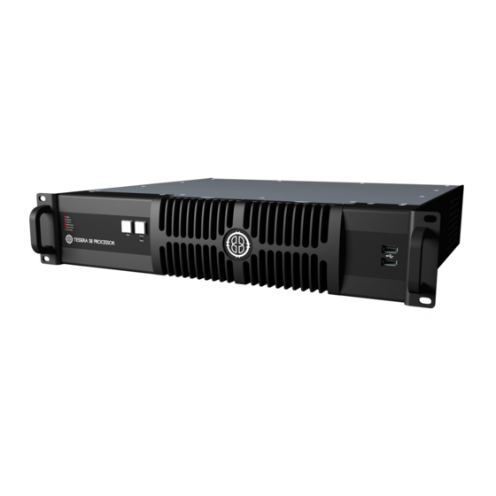
Page 23: Tessera S8 Led Processor
2.4 - Tessera S8 LED Processor 2.4.1 - Front Panel Feature Description Front Panel Status LEDs Blackout button Sends the output of the processor to black Freeze button Freezes the output of the processor Press to reset the processor, press and hold for 10 seconds to restore to factory Reset button settings. - Page 24 2.4.3 - Rear Panel Connections Feature Description Connect a PC or Mac running Tessera Remote, Tessera Control applications or an Management Ethernet eDMX protocol directly to the local data Gigabit Ethernet port. The two ports work as a switch to daisy-chain units. Tessera S8 LED Processor can be operated locally with a monitor connected via Local User Interface DisplayPort.
-
Page 25: Tessera M2 Led Processor
2.5 - Tessera M2 LED Processor 2.5.1 - Front Panel Feature Description Front panel status LEDs Press to reset the processor, press and hold for 10 seconds to restore to factory Reset button settings. Warning, this will delete all project files and Fixture Packs not included with the base firmware To connect USB memory storage devices and peripherals e.g. - Page 26 2.5.3 - Rear Panel Connections Feature Description Connect a PC or Mac running the Tessera Remote, Tessera Control application or Management Ethernet an eDMX protocol directly to the local data Gigabit Ethernet port. The two ports work as a switch to daisy-chain units. The Tessera M2 LED Processor can be operated locally with a monitor connected Local User Interface via DisplayPort.
-
Page 27: Tessera S4 Led Processor
2.6 - Tessera S4 LED Processor 2.6.1 - Front Panel Feature Description Front panel status LEDs Black button Sends the output of the processor to black Freeze button Freezes the output of the processor Press to reset the processor, press and hold for 10 seconds to restore to factory Reset button settings. - Page 28 2.6.3 - Rear Panel Connections Feature Description Connect a PC or Mac running the Tessera Remote, Tessera Control application or Management Ethernet an eDMX protocol directly to the local data Gigabit Ethernet port. The Tessera S4 LED Processor can be operated locally with a monitor connected Local User Interface via DisplayPort.
-
Page 29: Tessera T1 Led Processor
2.7 - Tessera T1 LED Processor 2.7.1 - Front Panel Feature Description Front panel status LEDs Press to reset the processor, press and hold for 10 seconds to restore to factory Reset button settings. Warning, this will delete all project files and Fixture Packs not included with the base firmware To connect USB memory storage devices and peripherals e.g. - Page 30 2.7.3 - Rear Panel connections Feature Description Connect a PC or Mac running the Tessera Remote, Tessera Control application or Management Ethernet an eDMX protocol directly to the local data Gigabit Ethernet port. The Tessera T1 LED Processor can be operated locally with a monitor connected Local User Interface via DisplayPort.
-
Page 31: Section 3 - Quickstart
Fixtures are required to be connected to the Tessera XD Unit. NOTE Tessera SX40 does not support sub-fixtures 2. Connect the video input source(s) to the DVI, HDMI and/or SDI input ports. 3. Connect a monitor to the Local UI using the DisplayPort connector and connect a mouse and keyboard. -
Page 32: Tessera Project Setup
1. From the Start Screen, select New to launch the Project Wizard. Fig 3.2 - The New Project Wizard on a Tessera SX40 LED Processor 1. The project name can be manually entered, if no entry is made, a default project name containing the processor’s model with a date and time stamp is assigned. -
Page 33: Connecting Fixtures
3.3 - Connecting Fixtures Fig 3.4 - Add Fixtures from Network button 1. Ensure that all fixtures are connected to the processor with the desired topology, taking into consideration the output port’s capacity limit. 2. Click the Add Fixtures From Network button. The canvas toolbar is replaced with a row of currently connected fixtures. - Page 34 5. Click on the canvas to add fixtures one by one. The currently selected fixture is highlighted in white on the LED panel. 6. Clicking and dragging will draw an array of fixtures. The topology is defined by the direction taken when drawing the array. 7.
-
Page 35: Section 4 - System Configuration
100BASE-T (Fast Ethernet) or 10BASE-T. The 10 gigabit connection between the Tessera XD and SX40 LED Processor must be direct, using fibre optic or Cat6a or above cabling. See Cable Requirements For Tessera SX40 and XD on page for more information. - Page 36 4.2.2 - 10 Gigabit Data Connection The connection between the Tessera SX40 LED Processor and its Tessera XD Distribution Units needs to be direct by using single-mode fibre-optic cables with PC or UPC DUO connectors for a length of up to 2 km or Cat6a or above cabling with RJ45 or EtherCON terminations to reach a...
-
Page 37: Redundancy Configuration
4.3 - Redundancy Configuration 4.3.1 - Closed Loop Redundancy Closed loop redundancy is supported on Tessera SX40, Tessera S8, M2 and S4 LED Processors where two outputs can be configured to operate as a redundant pair. Closed loop redundancy is not supported on Tessera T1 LED Processors as they only feature a single output. - Page 38 In the Tessera SX40 , 10Gb trunk pairs can be (independently) configured for redundant operation (A+B, C+D) however symmetry must be maintained. Fig 4.3 - Tessera interface with redundancy configured on trunks A and B Fixture chains must be connected to the same port of the same XD on both primary and backup trunks.
- Page 39 Fig 4.4 - Tessera SX40 configured with redundancy for trunks A and B and C and D When operating in redundancy mode: Fixtures can be cabled in a single chain of up to 50 fixtures, with each end of the chain connected back to the processor (or Tessera XD when using a Tessera SX40).
- Page 40 4.3.2 - Processor Redundancy Only available for the Tessera SX40, processor redundancy is designed as a backup system should the primary processor fail to send a signal to the fixtures. If the primary processor stops outputting video signal, the backup processor will detect the fault and re- associate fixtures.
- Page 41 External reference signals (if in use) may similarly be shared or independent between the two processors. 6. Both processors must be set up independently of each other. Set the project in both processors to display the desired image. Settings such as fixture position in the canvas, video input and colour correction can be modified independently, so precautions should be taken to avoid differences between processors.
- Page 42 Fig 4.7 - Tessera SX40 LED Processor and loop redundancy TESSERA - V3.1 | USER MANUAL - REV A | 4.3 - REDUNDANCY CONFIGURATION...
-
Page 43: Output Capacity
4.4 - Output Capacity The Tessera output port capacity depends primarily on the network bit depth and frame rate. The nominal pixel capacity per port is outlined in the table below, and when Ultra Low Latency (ULL) is added the pixel capacity is halved: Refresh/Bit 8 bpc 10 bpc... - Page 44 4.4.1 - Other Factors Affecting Output Capacity Fixture Rotation Rotating fixtures on-axis (i.e. by 0°, 90°, 180° or 270°) has no effect on the output capacity. Fig 4.8 - Example of rotating fixtures on-axis not effecting output capacity. However, each fixture rotated off-axis is counted twice towards the output capacity. Fig 4.9 - Example of rotating fixtures off-axis effecting output capacity.
- Page 45 Therefore, the number of these fixtures supported may be fewer than that calculated from the nominal pixel capacity. In terms of processing, the Tessera SX40 LED Processor considers any connected fixture to be at least 64px in either dimension, so the total number of fixtures per port might be affected.
-
Page 46: Combining Processors
4.5 - Combining Processors The Tessera SX40, S8, S4, T1, and M2 LED Processors are designed to be used together in a configuration without issues. Different types of processors can be used to run different sections of the same wall. -
Page 47: Section 5 - Tessera Management Software
Settings > Processor, select a resolution from the dropdown menu and click Commit. The minimum supported resolution for M2 , T1 , and S4 LED Processors is 1024x768 and the maximum resolution is 1920x1080. The Tessera S8 and Tessera SX40 LED Processor support UI resolutions of up to 3840x2160. -
Page 48: Installation For Windows Pc
The processor firmware can be updated from the remote app. 5.3 - Installation for Windows PC 1. Download Tessera Remote Windows software from our Brompton Support web page: https://www.bromptontech.com/support 2. Open the downloaded file to begin Setup Wizard. Hit Next to continue. - Page 49 TESSERA - V3.1 | USER MANUAL - REV A | 5.3 - INSTALLATION FOR WINDOWS PC...
-
Page 50: Installation For Mac Os
5.4 - Installation for Mac OS X 1. Download Tessera Remote Mac OSX installation file from Brompton ’s website https://www.bromptontech.com/support 2. Double click the .dmg file and drag the Tessera Remote icon into the Applications Folder, or copy (⌘ + C) and Paste (⌘ + V) the Tessera Remote icon into Applications folder 3. -
Page 51: Connecting To A Tessera Led Processor
5.6 - Connecting to a Tessera LED Processor Having physically connected a Mac or Windows PC to a Tessera LED Processor via network, launch the Tessera Remote application. This will open a dialogue box to start Tessera Remote or the Offline Editor. Fig 5.1 - Start up menu for Tessera Remote Click ‘Start Tessera Remote’... - Page 52 When reloading processor firmware, the processor is temporarily inaccessible while firmware is written to the processor. Once this process is complete, the processor will reboot before becoming accessible again. Discovered processors display the following details: User-defined name of the processor ...
- Page 53 5.6.2 - Disconnecting From the Processor When closing the app or disconnecting from the processor, several options can be selected. Closing the app: Fig 5.4 - Tessera Remote, closing the app options Disconnecting from the processor: Fig 5.5 - Tessera Remote, disconnection from processor options. ...
- Page 54 Clicking “Shutdown the processor” will shutdown the processor remotely. It will disappear from the network and won’t be accessible to the user however it will need to be powered down locally. If there is a monitor and mouse connected to the unit locally, the message “It is now safe to switch off the processor”...
-
Page 55: Multiple Processors Control
5.7 - Multiple Processors Control There are different approaches to control multiple processors: Use a single Tessera Remote instance - It is easy to connect and disconnect from different processors on a network. The output from the processors will continue uninterrupted when Tessera Remote is not connected. - Page 56 5.7.1 - Running Multiple Instances of Tessera Remote When controlling multiple processors from one computer it is recommended to use a fixed IP address on each processor and on the computer running Tessera Remote. It can also be helpful to name each processor. See Identification on page for more information.
-
Page 57: Section 6 - High Dynamic Range
SECTION 6 - HIGH DYNAMIC RANGE The Tessera SX40 and S8 LED Processors are capable of accepting and delivering the impressive image quality of HDR on LED screens. From Tessera version 3.0 onward High Dynamic Range output is fully featured and optimised with an updated processing pipeline offering enhanced processing capabilities and new exclusive features. -
Page 58: Hdr Features
The Tessera SX40 and S8 LED Processors accept HDR video input at up to 12 bits per colour, and can automatically detect the input signal properties via InfoFrames on the HDMI 2.0 port. All received metadata about the HDR source is also now visible from the input source tile. See... -
Page 59: Dynamic Calibration
6.3 - Dynamic Calibration Dynamic Calibration is a Brompton Technology made feature designed to unlock the full potential of LED panels to achieve previously unattainable image quality results. It is a completely new approach to calibrating LED panels that allows users to achieve unthinkable brightness levels and colour saturation. - Page 60 Dynamic Calibration is required in order to deliver "High Dynamic Range" on page 57. This is currently only available on the Tessera SX40 and S8 LED Processors and either Processor needs to be connected to LED panels that have been Dynamically Calibrated to deliver the full benefits of "High Dynamic Range"...
-
Page 61: Section 7 - Project Setup
SECTION 7 - PROJECT SETUP 7.1 - Project Management 7.1.1 - Opening and Importing Projects Select a project from the list then click Open from the left menu. You can also import projects from USB drives or the local computer storage drive. Fig 7.1 - Importing projects in the project management screen To import a project using the processor: 1. - Page 62 2. Select the file and click OK. The project file is copied to the list of projects stored on the processor. 7.1.2 - Exporting Projects In the remote app, to export a project stored in the processor, select the desired project from the project management screen and click Export project to select the location.
- Page 63 7.1.4 - Creating a New Project on Local UI and Tessera Remote Fig 7.3 - The New Project window on a Tessera SX40 To start a new project, select New on the project management screen. Once the New Project Wizard launches: 1.
- Page 64 LED Processors if canvas sizes other than 1920x1080 are used. Ticking the Enable HDR checkbox will modify the EDID of the processor (SX40 and S8) signalling to the source that it is able to receive HDR video. 4. The Tessera SX40 and S8 feature custom resolutions. See Custom Canvas Resolution page for more information.
-
Page 65: Enable Hdr
Fig 7.5 - Enable HDR checkbox in Project Setup (left) and Canvas Properties (right) On the HDR capable Tessera SX40 and S8 LED Processor s the Enable HDR feature can be enabled by ticking the checkbox located within either the New Project window (Local... - Page 66 7.3.1 - Custom Canvas Resolution Only available for the Tessera SX40 and S8 LED Processors, the user can enter a canvas size of their choosing, unrestricted by aspect ratio. Fig 7.6 - The Canvas Properties, the user can adjust the canvas size on the fly There are some rules to bear in mind when using custom resolutions.
-
Page 67: Low Latency Mode
1:1 in the top left corner of the canvas. The Tessera SX40 and SX40 LED Processors do not have a Low Latency Mode, keeping all its features available at 2 frames latency end to end. To decrease their latency to 1 frame they can use Ultra Low Latency, though this has its own trade-offs. -
Page 68: Mapping Options
7.5 - Mapping Options Interpolation can be activated from the Canvas properties. Tessera projects can be set to work in two different mapping modes depending on the requirements. See Canvas Properties on page for more information. When working in 1:1, the physical size and pixel pitch is not taken into account, every pixel is sent to the correspondent position, independently of the fixture size. - Page 69 7.5.1 - Port Capacity in 1:1 or Interpolated When using 1:1 mapping, the output capacity is not affected. In interpolated mapping, the content on fixtures with a coarser pixel pitch is scaled to take the panel size into consideration, so that content appears the same size across all fixtures. For example, assume we have a project with three fixture types: ...
- Page 70 Per- fixture and per- group colour override - Colour and brightness settings can be superseded for specific fixtures or groups by enabling Override Global Colour on the Fixture Properties editor. See Per- Fixture and Per- Group Colour Override on page more information.
-
Page 71: Section 8 - Fixtures
SECTION 8 - FIXTURES 8.1 - Fixture Libraries To correctly communicate with fixtures, the processor needs to have the fixture firmware included in the fixture library of the processor. A Fixture Pack is installed with every version of the processor’s firmware and updated Fixture Packs can be found on our website. See Fixture Library on page... - Page 72 8.2.1 - Fixture Fixture displays basic information about the selected fixture including manufacturer, fixture type and the name of the group containing the fixture. The second section of this editor displays the position and rotation of the fixture in the canvas. Modifications can be made by typing or using the spin box arrows.
- Page 73 All the previous settings Brightness (Colour) Temperature Gamma NOTE Once a selection has been overridden on the Colour property editor, the Global Colour controls have no effect on the selected fixtures until the checkbox for Override Global Colour is unchecked. TESSERA - V3.1 | USER MANUAL - REV A | 8.2 - FIXTURE PROPERTIES...
-
Page 74: Device Properties
8.3 - Device Properties The device property editor shows information stored on the R2 receiver card. 8.3.1 - Fixture Quick Access Buttons In the title bar for the Device property editor, there are three quick access buttons: Reset: Reboots the fixture, video will stop displaying in the following devices connected in the same string, as data is not passed through while the fixture is rebooting. - Page 75 Fig 8.4 - Internal Test Pattern drop-down menu Although fixture models vary, most fixtures have a self-test button on the back of the fixture which can be used to activate test patterns by holding on the button for 4 seconds. (Refer to fixture manufacturer documentation for specific functionality).
-
Page 76: Osd
8.3.5 - Disable Status Indicator The status indicator of the root nodes can be disabled if necessary, by toggling the tick box. 8.3.6 - Sensors Information Information from sensors such as temperature or humidity is displayed if available in the fixture. -
Page 77: Studio Mode
8.5 - Studio mode Studio Mode reduces a fixture's maximum brightness while maintaining the PWM bit depth, thereby resulting in improved image quality (with less banding) when running at low brightness. The maximum benefit is seen on particularly bright fixtures, especially those running at relatively low PWM bit depth (14 bit or below). -
Page 78: Thermacal
Fig 8.8 - Effects of a ThermaCal correction IMPORTANT ThermaCal will only be available on a particular LED panel type / model after it has undergone a profiling procedure. Please contact our Brompton Support Team at support@bromptontech.com to check whether your panels have already been profiled. - Page 79 8.6.1 - Applying a ThermaCal Correction ThermaCal is available on all Tessera LED Processor s that are paired with Dynamically Calibrated LED panels. Any ThermaCal correction is applied at the panel-level. Fig 8.9 - ThermaCal controls within the Device Properties Should cyan patterning occur, apply a ThermaCal correction by: 1.
-
Page 80: Fixture Context Menu
8.7 - Fixture Context Menu Right-click a fixture to open a context menu with a list of options. These options are grouped by type and some options have keyboard shortcuts displayed on the right side column. If a fixture is un-associated, some options are unavailable. Fig 8.11 - Fixture context menu options TESSERA - V3.1 | USER MANUAL - REV A | 8.7 - FIXTURE CONTEXT MENU... - Page 81 Function Description Copy Copy the fixture Paste the fixture in the canvas The rotation value is also added but other values such as the modifications in the Paste fixture Colour property editor (see Fixture Properties on page 71) are not copied into the new fixture.
-
Page 82: Adding Fixtures To A Project
8.8 - Adding Fixtures to a Project There are two main workflows for adding fixtures to a project. With fixtures connected to the processor. The project and fixture layout are created on a processor with fixtures physically connected. In this case use Add Fixtures from Network ... - Page 83 Fig 8.14 - Click on either port A or B to associate to canvas Fig 8.15 - Tessera SX40 with Tessera XD Units, select one to associate to canvas TESSERA - V3.1 | USER MANUAL - REV A | 8.9 - ADD FIXTURES FROM NETWORK...
- Page 84 The Tessera T1 LED Processor only has a single output port so there is no port selection and only displays available strings of fixtures. For the Tessera SX40 LED Processor, the user needs to first select the trunk where the Tessera XD is connected before continuing to ports compared to other processors. ...
- Page 85 NOTE Tessera SX40 or S4 LED Processors only support grid arrays, circle/radial are not available. Grid Arrays Contain a set of options to allow the user to adjust position, change grid size, define spacing between fixtures or rotate to a desired location.
- Page 86 Fig 8.18 - Circle fixture layout property editor Radial Arrays Differs to the circle option by offering the option to place multiple fixtures in a circle, spanning outwards to create a wider display. Unique options with Radial include adjusting the quantity of fixtures used per spoke, the width and distance between fixtures.
-
Page 87: Add Fixtures From Library
8.10 - Add Fixtures from Library It is possible to work offline and create a layout when fixtures are not connected to the processor in one of two ways. Tessera Offline Editor in Tessera Remote or the local user interface, in each case the user will need to add fixtures from library as no fixtures are connected and nothing will appear in the add fixtures from network window. - Page 88 associate the fixture to the string. 2. If only part of the string is required, hold the Shift key and select the last fixture to associate. 3. Alternatively, continue to associate fixtures individually by clicking each fixture on the canvas in turn. If the user creates a new topology for panels which have already been associated, the old topology will be discarded in favour of the new topology/association.
-
Page 89: Sub-Fixtures
100 pixels. NOTE As on other processors, the fixture limit on Tessera SX40 also applies to sub-fixtures. (I.e. 2000 fixtures, sub-fixtures, or a combination of the two.) Sub-fixtures which are smaller than 64 pixels in one or both dimensions have these dimensions rounded up to 64 when calculating the processor load. - Page 90 8.12.1 - Sub-Fixtures Properties The Fixture property editor is displayed when selecting an online root node or sub-fixture from the canvas or the online view. See Fixture Properties on page for more information. Root Nodes Properties Fig 8.22 - Device property editor The device property editor shows the information of the Tessera R2 Receiver Card and the root node.
- Page 91 Configure root node Allows the user to specify sub-fixtures on each port. See Configuring the Root Nodes Online on page for more information. Copy root node configuration Copy the configuration for the selected root node. Paste root node configuration Paste the copied configuration for the selected root node.
- Page 92 8.12.3 - Associating Sub-Fixtures Sub-fixtures may be individually positioned and rotated on the canvas, just like normal fixtures. Root nodes are not typically able to detect what types and quantities of sub- fixtures are connected to their outputs and must be assigned by the processor. Root nodes can be added to the canvas using the Add Fixtures from Library or Add Fixtures from Network tools.
- Page 93 Configuring the Root Nodes Online Using Add Fixtures from Network . The root nodes need to be connected to the processor and online. 1. Click Add Fixtures from Library or Add Fixtures from Network 2. Select your root node and place it on the canvas. 3.
- Page 94 Offline Using Add Fixtures from Library 1. Click Add Fixtures from Library. 2. Select the root nodes and place on the canvas. The search bar can be used to filter fixtures. Fig 8.28 - Adding a Root node to canvas 3.
- Page 95 Online Using Add Fixtures from Network This option restricts the addition of sub- fixtures to the configuration of the root node. The processor does not receive information regarding the number of connected sub-fixtures. 1. Click Add Fixtures from Network 2. Select the port for connected fixtures. 3.
- Page 96 fixtures. When a root node is associated, its outputs are automatically associated with the correct types of root node, and the sub-fixtures will automatically be associated. It is not normally necessary to individually associate sub-fixtures. If a sub-fixture doesn’t appear associated, the root node can be disassociated by right-clicking and selecting Disassociate.
-
Page 97: Understanding Topology And Association
8.13 - Understanding Topology and Association Tessera LED Processors can detect the topology of connected fixtures. Topology is the order which fixtures are connected, which port on the processor they are connected to and if fixtures are broken into strings by switches. The topology tools are used to help users associate physical fixtures with fixtures on the canvas. - Page 98 from network button , which usually has a green status indicator when the fixture is online, will now turn grey. In instances where a fixture is swapped out from the string, the processor will detect a disappearance and a new fixture will appear in the same position. The processor will detect a swap-out has taken place and will offer the user the option to perform Correct Association.
- Page 99 Changing Physical Topology If the fixtures’ topology is modified, for example to balance the ports load, the fixtures are automatically re-associated. Example: The fixtures in a wall are associated to the processor in a topology using ports 1 and 2 as shown below: Fig 8.35 - Fixtures with topology changed to balance Fig 8.34 - Fixtures associated to the processor using...
- Page 100 The Correct Association option can be also done by selecting Correct Association from the Edit dropdown menu or in the Edit topology toolbar menu . Pressing the correct association button repairs the canvas topology. Changing Canvas Topology The topology can be manually changed using the topology toolbar that appears when pressing the Edit Topology button.
- Page 101 Fig 8.39 - Second topology To correct the screen, use the following steps: 1. On the canvas select all fixtures with the incorrect topology. Right-click the fixtures and select Disassociate. 2. Click Edit Topology to view the Topology toolbar and select the string of fixtures requiring correction by double- clicking on the dot in the centre of a fixture.
- Page 102 4. Hover the mouse over the centre spot of the fixture which is to be at the start of the string. Click and drag the pointer to the centre spot of the second fixture on the string. A dotted red line is drawn which turns solid as the line becomes pinned to the centre spot of the next fixture in the string.
- Page 103 7. Once corrections are complete, return to the main project view by pressing Esc or clicking on the arrow located at the top left of the interface . The processor detects a new topology which doesn’t match the current association and displays the Correct Association message for 10 seconds.
-
Page 104: Fixture Layout
8.14 - Fixture Layout 8.14.1 - Selecting Individual Fixtures Click to select a fixture. The fixture will turn blue and the Fixture property editor will be displayed on the right side of the user interface. See Fixture Properties on page for more information. - Page 105 Group Properties The Group property editor appears when a group is selected. It is composed of Group and Colour. Fig 8.45 - Group properties Group The group property editor is divided in three sections. Group info Name: Change the name of the group. ...
- Page 106 Position The second section of this property editor displays the position and rotation of the fixture in the canvas. Changes can be locked to avoid modifications. Modifications can be done by typing or using the spin box arrows. The Reorient button rotates the fixture by 90 degrees clockwise for square fixtures, or 180 degrees for rectangular fixtures.
- Page 107 8.14.5 - Rotating Fixtures Fixtures can be rotated by 90-degree increments on all processors, however Tessera M2 and T1 LED processors support free rotation, allowing rotation to any degree at a cost of doubling the bandwidth required to drive the fixtures. Fig 8.47 - Network load is increased when rotating fixtures by 90 degrees Fixtures can be individually rotated around their top-left corners by first selecting the fixture, then either click the rotation icon in the toolbar...
- Page 108 Fixtures can also be rotated during association by pressing the Alt key and using the mouse wheel to change the rotation angle. NOTE The Tessera SX40, S8, and S4 LED Processors can only rotate in 90-degree increments. Other Factors Affecting Output Capacity...
-
Page 109: Section 9 - Main Project Screen
LED devices, and troubleshooting. Topology view (only in Tessera SX40 ): Provides a representation of the connections between the processors, XD Units and fixtures. ... - Page 110 9.1.1 - Canvas Properties The canvas properties editor can be accessed by selecting Properties in the canvas properties toolbar, on the top-right of the canvas. Fig 9.2 - Canvas properties Size The canvas size can be freely modified however the input source must fit within the width and height dimensions.
- Page 111 9.1.2 - Background Show Toggle to enable or disable the background view. Click Browse to navigate to a image file. JPG or PNG files are compatible. File Select Browse to select a file from the USB drive or computer (when in Remote mode) to display in the background on the canvas.
- Page 112 Canvas Edits Enabled Enables or disables modifiying the active area size or position of the canvas. This can be done by clicking the edges of the canvas and dragging to resize it. Active Area on page for more information. TESSERA - V3.1 | USER MANUAL - REV A | 9.1 - CANVAS VIEW...
- Page 113 9.1.4 - Canvas Context Menu Right- click an unused area of the canvas to open a context menu with a list of options to customize the appearance and usability of the canvas. Fig 9.3 - Context menu when right-clicking unused area on canvas Function Description Paste...
- Page 114 9.1.5 - Canvas Toolbar The Main Toolbar offers a selection of tools to draw fixtures on the canvas and select zoom and view positions. Fig 9.4 - Canvas toolbar features Icon Icon Description Description Undo and redo the last action performed. The shortcut commands Undo/Redo arrows for Undo is Ctrl+Z (⌘...
- Page 115 9.1.6 - CANVAS Edit Views Edit Mode Edit Mode views allow fixtures to be positioned on the canvas. Edit Mode: Keyboard Shortcut: F1 Edit Mode is the default mode for the canvas and allows fixture positioning. In Edit mode the fixtures are displayed as viewed from the front.
- Page 116 Video On Canvas Mode The Video on Canvas Mode view displays the currently selected video input onto the Canvas, including Viewport and Active Area settings. This mode shows how input content is displayed on fixtures in real-time. NOTE Video on Canvas mode is not available when: ...
- Page 117 Fixture Only Mode: Keyboard Shortcut: F3 Fixture only mode displays the currently selected video input as it is being displayed on the fixtures. Video and Fixture Mode: Keyboard Shortcut: F4 Video and Fixture Mode displays the current video input on both the fixtures and the canvas. The video within the Active Area that is not being displayed on the fixtures is shown greyed out as shown in the picture below.
- Page 118 Video Only Mode Keyboard Shortcut: F5 Video Only Mode displays the current video input within the Active Area on the canvas without displaying the fixtures. This mode is useful to preview the input source size and position in the canvas. Heat Map Keyboard Shortcut F6 Selecting 'Heat Map' from the canvas display mode button (or pressing F6) displays fixtures on...
- Page 119 fixtures display colour representing temperature. Temperatures ranging from the coolest fixtures (black) to the hottest fixtures (white). Fixtures that are offline or that haven't reported a temperature are displayed with a grey hatched pattern. Layers Fig 9.5 - The Layers property editor Layers are an easy way of managing overlapping fixtures.
- Page 120 To assign fixtures to layers, select the fixture and right-click. Under Move to Layer, select the layer to use. Properties Area When working in canvas mode, the Properties area is located on the right side of the screen. It can be shown or hidden by clicking the double- arrow button placed next to the canvas properties toolbar.
- Page 121 NOTE The property editor for a selection of groups/fixtures only displays common settings. The positions, rotation and colour modifications are applied to all selected objects. Pin Property Editor Widgets to Properties Area To pin and fix a property editor widget to the properties area so it does not disappear when a different object is selected, press the pin button located on the right side of the editor title bar.
- Page 122 Unselected Pipeline tile is disabled Single click Pipeline tile disabled, property editor shown Pipeline tile enabled, property editor not shown unless pinned to Double click property area Double click Pipeline tile enabled, property editor shown Open the Property Editor Pipeline tile properties can be viewed and adjusted by single clicking on a tile to prompt the property editor to appear.
-
Page 123: Presets
9.2 - Presets At the bottom of the Main Project Screen, presets can be set to store settings on the processor. Presets can be made to affect all fixtures, a selection of fixtures or groups. The video source modifications affects all fixtures on the canvas. Available options to save into presets include: ... - Page 124 9.2.1 - Using Masking Fig 9.8 - Preset Recording view Masking is useful for security when changing fixture position without altering colour information or to change the input source without affecting the global colour. When a preset is stored, three icons appear after pressing the Record button. The icons represent information that will be stored within the preset.
- Page 125 6. Only selected groups are stored into a Position preset. Once selected, the diagonal lines on the groups change to solid colour. If no group is selected, the following warning is shown. 7. Click an empty preset tile to store the new preset. 8.
- Page 126 Name Option to rename the preset tile Fade Time Select the cross-fade time Fade Through Black Activate to go to black before crossfading to the new source input Cross-fading This feature is only available on the Tessera M2 LED Processor Switching inputs can be achieved by creating a Video preset for each input. NOTE Other values like Colour and Position are not affected by the fade times and are committed as soon as the preset is activated.
-
Page 127: Log
9.3 - Log Information about the processes and errors that occur within the processor can be viewed by clicking on Log. This information can be stored in a USB drive or on the computer using the button Save the Log TESSERA - V3.1 | USER MANUAL - REV A | 9.3 - LOG... -
Page 128: Moving Around The Canvas
9.4 - Moving Around the Canvas Move Controls Vertical scrollbar Arrow keys Page up/down keys Up, down, left and right Mouse wheel Horizontal scrollbar Arrow keys Shift + mouse wheel in the main toolbar Zoom in and out Ctrl + mouse wheel Zoom to fit, Zoom 1:1 or Zoom to selection options Drag the canvas Hold the space bar and left-click + drag with the mouse... -
Page 129: Project Data Export
9.5 - Project Data Export Tessera software has three types of files that can be exported: Canvas image, device layout and discovered devices. 9.5.1 - Export Canvas Image To export an image, navigate to Tools and select Export Canvas Image. Several options are displayed for the user to choose and control how exported images are rendered. - Page 130 Port 1 Status Port 2 Status Temperature Orientation Status Authentication Navigate to the Tools dropdown menu and select Export Discovered Devices or from Online view and selecting Export Discovered Panels. Data is exported in Comma-Separated Values (CSV) format.The exported data can be opened and manipulated in spreadsheet applications such as Microsoft Excel, or in simple text editors.
-
Page 131: Online View
9.6 - Online View The Online Fixtures view provides comprehensive information about all fixtures currently detected by the processors output ports. 9.6.1 - Exporting Online Fixture Data To export information regarding connected fixtures, navigate to either the Tools drop- down menu or the Online view and click the Export Discovered Devices button. - Page 132 The error counter values are not reset by events such as the link going up or down, or the fixture being disconnected and reconnected. This is useful for long-term tests as an unexpected disconnection does not increase the error count. A small number of receive errors can be expected when hot- plugging data cables or power cycling fixtures or processor.
-
Page 133: Topology View
Tessera XD Units and fixtures. On the left, the letters A, B, C, & D represent the physical ports of the Tessera SX40. Green arrows represent a connection between the processor ports to any connected Tessera XD Distribution Units and their ports. -
Page 134: Section 10 - Inputs
Until sources are connected to the Tessera Processor the tiles will display icons relating to the available inputs. Fig 10.1 - Source pipeline tile icons when no source is connected on a Tessera SX40 LED Processor 10.1 - Source Selection Video inputs can be selected from the user interface when a connection is detected. -
Page 135: Hd Sources (For M2, T1, S4)
Genlock Settings on page more information. 10.2 - HD Sources (for M2, T1, S4) Fig 10.3 - Input Sources for Tessera SX40 10.2.1 - 3G SDI Input (M2 only) Each SDI input on the Tessera M2 LED Processor provides support for: ... -
Page 136: 4K Sources (For Sx40 And S8)
10.3.2 - HDMI 2.0 Input Both the Tessera SX40 and Tessera S8 LED Processor supports HDMI 2.0 signals up to 4k DCI with customised resolutions at frame rates from 24Hz to 144Hz with 18Gbps bandwidth to a maximum pixel clock of 600MHz. The Tessera LED Processors do not support HDCP. - Page 137 The supported video properties are: 8, 10 or 12 bits per channel YCbCr 4:2:0 YCbCr 4:2:2 YCbCr 4:4:4 In addition to the HDMI 2.0 input there is also a re-clocked HDMI 2.0 output. TESSERA - V3.1 | USER MANUAL - REV A | 10.3 - 4K SOURCES (FOR SX40 AND S8)
-
Page 138: Input Metadata
Metadata is received from the source via InfoFrames over an HDMI 2.0 connection for the Tessera SX40 and Tessera S8 LED Processor s. The metadata contains information about the content's format, brightness, and colour space allowing the Tessera SX40 and Tessera S8 LED Processors to automatically set these values for the received input. - Page 139 Metadata Property Property Explanation Status Status of the incoming source signal Resolution Resolution of content being received from the source Frame Rate Frame rate of the content being received from the source Sampling Chroma subsampling compression of the incoming content Bit Depth Bit depth of the incoming content.
- Page 140 10.4.2 - SDI (SX40, S8, M2) Fig 10.5 - Incoming metadata from an HDR source through SDI The SDI input does not send any metadata of the incoming content (beyond the resolution and frame rate) so information such as the colour space and HDR format (SX40 and S8 only) will have to be provided manually from the Input Override.
- Page 141 10.4.3 - DVI (M2, S4, T1) Fig 10.6 - Incoming metadata from an HDR source through SDI Like SDI, DVI inputs do not send any metadata for the incoming content beyond the resolution and frame rate. Information about the colour format and colour space need to be set manually from the Input Override.See Input Override on page...
-
Page 142: Input Override
Fig 10.7 - Input override controls for the Tessera SX40 and S8 Because the Tessera SX40 and Tessera S8 LED Processors are capable of outputting HDR they have dedicated input override controls to set the required properties for incoming HDR content. - Page 143 10.5.1 - HDMI 2.0 (SX40 and S8) With HDMI 2.0 inputs only available on our HDR capable Tessera SX40 or Tessera S8 LED Processors the input override controls will only appear as shown in "Input override controls for the Tessera SX40 and S8" on the previous page...
- Page 144 10.5.2 - SDI (SX40, S8, M2) Fig 10.8 - Input override controls for SDI inputs on the Tessera SX40 (left) and M2 (right) Both the Tessera SX40 and Tessera M2 LED Processors can receive SDI inputs. Only the Tessera SX40 and S8 are HDR capable meaning their input override controls are more extensive than for the Tessera M2 which allows only for the colour space to be set.
- Page 145 10.5.3 - DVI (M2, S4, T1) Fig 10.9 - Input override controls for DVI inputs NOTE DVI connections do not provide any metadata for setting the input format properties. This means the values will need to be set manually. For the Tessera M2, S4, and T1 they are set to the values shown above. Metadata Property Property Explanation Define the incoming colour format, whether uncompressed RGB or YPbPr of...
-
Page 146: Input Colour Control
10.6 - Input Colour Control 10.6.1 - Black Level The black level control affects the base level brightness of the darkest content for the incoming feed. Modifying this value will affect the signal gradually but will be most pronounced at the lower end of the video signal nearest black. -
Page 147: Histograms
10.7 - Histograms Tessera LED Processors offer a selection of histograms to depict distribution of pixels across the possible range of a colour or colours of the incoming video feed in real time after they have been modified by the input colour controls. There are six different histograms available, and all histograms can be displayed linearly or logarithmically: ... - Page 148 Fig 10.11 - Test pattern showing colour bars at 75% and the corresponding Logarithmic RGB histogram The above picture shows a logarithmic visualization of the input. Although the same three areas 0%, 75% and 100% show the highest concentrations of columns, there are now more areas visible.
- Page 149 10.7.1 - Setting Colour Controls with the Aid of Histograms Histograms are useful for determining if an incoming signal is filling the entire spectrum of colour and brightness. NOTE When choosing an image to balance, use an image from live event content throughout the project, an image with a wide variety of colours and hues, or a suitable test pattern.
- Page 150 Fig 10.13 - Adjusting the black level control will make the blacks look darker and the concentrations of colour now reach down to 0% on the scale TESSERA - V3.1 | USER MANUAL - REV A | 10.7 - HISTOGRAMS...
- Page 151 Fig 10.14 - Adjusting the contrast control will make brighter areas appear closer to the 100% threshold, assuming some areas contain white content in the image and is desirable NOTE If specific colours do not render correctly, adjust RGB Highlight and Shadow controls to work on that specific colour without affecting the other two primaries.
-
Page 152: Section 11 - Processing
11.1 - Scaling and Cropping The Tessera M2 and T1 LED processors support scaling and cropping of the incoming feed. The Tessera SX40 and S8 LED processors support scaling. These functions are achieved using two settings: Viewport and Active Area. - Page 153 11.1.1 - Viewport The Viewport settings define the region of interest from the incoming feed which is captured to the canvas. By default, when activating the Scaler pipeline tile, the settings will be set to fit the canvas, with full size viewport and full size Active Area with stretch Zoom mode. The Viewport is scaled and mapped onto the Active Area according to the Zoom mode.
- Page 154 1:1 Mode The 1:1 mode selects and crops an area of the input maintaining the original Viewport image size. Dimensions Left: Determine the column of pixels that will appear on the left of the canvas Top: Determine the row of pixels that will appear on the top of the canvas ...
- Page 155 Fit Mode The Fit mode selects a section of the input and scales it to fit within the active area while maintaining the aspect ratio. Dimensions Left: Determine the column of pixels that will appear on the left of the canvas ...
- Page 156 Fill Mode The Fill mode selects a section of the input and scales it to fill the active area while maintaining the aspect ratio. Dimensions Left: Determine the column of pixels that will appear on the left of the canvas ...
-
Page 157: Scaling And Cropping
11.2 - Scaling and Cropping The Tessera M2 and T1 LED processors support scaling and cropping of the incoming feed. The Tessera SX40 and S8 LED processors support scaling. These functions are achieved using two settings: Viewport and Active Area. - Page 158 Fig 11.8 - Scaler property editor 11.2.1 - Viewport The Viewport settings define the region of interest from the incoming feed which is captured to the canvas. By default, when activating the Scaler pipeline tile, the settings will be set to fit the canvas, with full size viewport and full size Active Area with stretch Zoom mode.
- Page 159 Fig 11.9 - Scaler zoom mode options 1:1 Mode The 1:1 mode selects and crops an area of the input maintaining the original Viewport image size. Dimensions Left: Determine the column of pixels that will appear on the left of the canvas ...
- Page 160 Fig 11.10 - Canvas is scaled to 1:1 TESSERA - V3.1 | USER MANUAL - REV A | 11.2 - SCALING AND CROPPING...
- Page 161 Fit Mode The Fit mode selects a section of the input and scales it to fit within the active area while maintaining the aspect ratio. Dimensions Left: Determine the column of pixels that will appear on the left of the canvas ...
- Page 162 Fill Mode The Fill mode selects a section of the input and scales it to fill the active area while maintaining the aspect ratio. Dimensions Left: Determine the column of pixels that will appear on the left of the canvas ...
- Page 163 Stretch Mode The Stretch mode selects a section of the input and stretches it to fill the active area and match its width and height. Dimensions Left: Determine the column of pixels that will appear on the left of the canvas ...
-
Page 164: Active Area
11.3 - Active Area On the canvas, the Active Area is indicated by the grey mask with a dashed border. Fig 11.14 - The canvas with the Active Area shown by a dashed border Having determined the region of interest to be captured from the incoming feed using the Viewport, that region can then be sized or moved as desired. - Page 165 Fig 11.15 - Scaler property editor 11.3.1 - Aspect Ratio The Aspect Ratio value will force the dimensions into a standard ratio (4:3 or 16:9). Select “Free” to allow flexible modifications of the content. Dimensions Left: Determine the position of the left edge of the active area ...
- Page 166 NOTE The active area cannot be greater than the maximum canvas size. To modify the active area, move the mouse cursor to the top-left corner of the active area until it becomes a hand , then click and drag the area. Positions can also be determined by adjusting the top and left coordinates manually.
- Page 167 Snap to Canvas Adjust the active area size to match the canvas size. Fig 11.18 - The active are is set to the canvas dimensions TESSERA - V3.1 | USER MANUAL - REV A | 11.3 - ACTIVE AREA...
-
Page 168: Chromatune
11.4 - ChromaTune Fig 11.19 - ChromaTune pipeline tiles: Colour Replace, 14-Way Colour Correction, and Curves ChromaTune consists of two advanced colour correction features. One is Colour Replace, which gives the user advanced control to manipulate one specific colour with flexibility. The other is 14-way Colour Correction which enables adjusting one or a number of pre-defined colours by modifying their Hue, Saturation or Brightness. - Page 169 Fig 11.21 - Selecting a colour from the colour picker. Colour Tolerance: Determines the Hue range that is affected by the modifications. Brightness Tolerance: Determines the Brightness range that is affected by the modifications. Apply to Hue, Apply to Saturation, Apply to Brightness These checkboxes apply the tolerance settings to their respective parameters.
- Page 170 Colour Replace Examples A red pepper can be changed into green pepper easily. Here is the original red pepper image: Fig 11.23 - Original red pepper Select a red colour from the from the canvas using the eyedropper tool, and a suitable green from the colour picker: Fig 11.24 - From and To colour chips with red changed to green.
- Page 171 Fig 11.26 - The resulting green pepper after increasing the Hue Tolerance It is recommended to use the View Matte feature when using Colour Replace, as this shows the areas of the image that will be affected by the colour replace operation. Fig 11.27 - The View Matte feature TESSERA - V3.1 | USER MANUAL - REV A | 11.4 - CHROMATUNE...
- Page 172 11.4.2 - 14-way Colour Correct Fig 11.28 - 14 way colour correct pipeline tile with all colours adjusted The 14- way Colour Correct feature allows singular or multiple pre- defined colours to be adjusted without affecting other colours. Hue, saturation and brightness controls are provided for each of the primary, secondary and tertiary colours.
- Page 173 In addition to the Colour Replace and 14- Way Colour Corrector features, from Tessera v2.3 onwards on the Tessera SX40 and S8 LED Processors, ChromaTune now offers curves covering red, green, blue and white channels. This enables the video levels for each colour channel to be manipulated by creating custom transfer curves.
-
Page 174: Section 12 - Test Patterns
SECTION 12 - TEST PATTERNS Fig 12.1 - Test Pattern Pipeline tile in deactivated state 12.1 - Processor Test Patterns All Tessera LED Processor s have a selection of test patterns that can be used to check the performance of fixtures and verify that a fixture layout is correct. Scrolling test patterns will always move exactly one pixel horizontally and/or vertically, therefore motion should be perfectly smooth. -
Page 175: Custom Test Patterns
12.2 - Custom Test Patterns The Custom Test Patterns section allows for custom images to be loaded into the processor or captured from the video input. Fig 12.4 - Custom Test Pattern Options To use a custom test pattern, select the Pattern pipeline tile under Override in Canvas View. ... -
Page 176: Fixture Test Patterns
Blackout property editor. 12.5 - Front Panel Button Settings Tessera SX40 S8 and S4 LED Processors feature 2 buttons on the front panel to freeze or blackout the output on fixtures. By default, these perform the same functions as the buttons in the GUI. - Page 177 Fig 12.7 - Tessera Test pattern property editor, with Freeze button behaviour drop-down menu options If needed, failover can also be triggered by pressing both buttons at the same time when Tessera SX40 is cabled for Processor redundancy. This can be enabled or disabled in the Failover property editor.
-
Page 178: Section 13 - Global Colour
SECTION 13 - GLOBAL COLOUR The following controls are available in the Global Colour pipeline tile and apply to all fixtures in a project unless those fixtures (or groups) have been overridden. See Per-Fixture and Per-Group Colour Override on page for more information. -
Page 179: Brightness
13.1 - Brightness The brightness slider allows adjustments for light output on fixtures. As all fixture types are calibrated when the profile is written, the brightness slider is expressed in Nits (candela/m2). This means arrays with different fixtures can quickly be set to the same output level. Where more than one type of fixture with different maximum brightness values is used, the slider has no effect on a fixture's brightness once its maximum value is exceeded. - Page 180 NOTE Prior Mac OSX versions to Snow Leopard encoded at 0.55 and hence decoded at 1.8. In order to obtain best results, a lower gamma value on the display output was set. Since Mac OSX Snow Leopard release, Apple has changed their default gamma values to a value more in line with the 0.45/2.2 ratio used by other manufacturers.
-
Page 181: Dark Magic
13.4 - Dark Magic LED panels are often run at a lower brightness than their maximum capability, e.g. for indoor and 'on- camera' applications. This results in an unavoidable reduction in effective bit depth, which can lead to visible artefacts such as banding and loss of detail, especially in dark areas of the image. - Page 182 Fig 13.4 - Dark Magic disabled with visible banding, compared with enabled TESSERA - V3.1 | USER MANUAL - REV A | 13.4 - DARK MAGIC...
-
Page 183: Puretone
Fig 13.5 - Brightness non-linear response of RGB channels and example of PureTone greyscale colour cast correction IMPORTANT PureTone will only be available on a particular LED panel type / model after it has undergone a profiling procedure. Please contact our Brompton Support Team at support@bromptontech.com to check whether your panels have already been profiled. -
Page 184: Gain Controls
13.5.1 - Enabling PureTone Fig 13.6 - Brightness non-linear response of RGB channels and example of PureTone greyscale colour cast correction PureTone is available on all Tessera LED Processors that are paired with Dynamically Calibrated LED panels. It is a global feature that once enabled will apply the PureTone correction to all LED panels. -
Page 185: Studio Mode
See Fixture Properties on page for more information. NOTE Not all LED panels will support Studio Mode. Please contact our Brompton Support Team at support@bromptontech.com to check whether your panels support this feature. TESSERA - V3.1 | USER MANUAL - REV A | 13.7 - STUDIO MODE... -
Page 186: On-Screen Colour Adjustment
13.8 - On-Screen Colour Adjustment Tessera LED Processors feature a comprehensive fixture-based seam adjustment for fixture and module seams, and 7-way colour correction for modules and panels. OSCA is an abbreviation for On- Screen Colour Adjustment. When in OSCA Mode, the OSCA interface appears on the output fixtures themselves, showing the mouse position and highlighting selected seams, fixtures or modules for quick and intuitive adjustments. - Page 187 Fig 13.9 - The disable video output warning Fig 13.10 - The On-Screen Colour Adjustment window The On- Screen Colour Adjustment window displays the fixtures in the project as they are positioned on the canvas. The mouse can select fixtures or seams and using the keyboard arrow keys will change the selected object.
- Page 188 Fig 13.11 - The Video button on the OSCA toolbar, click or alternatively press Tab on the keyboard. OSCA works in one of two modes: Seam Adjustment, which allows the luminance adjustment of fixtures and fixture modules, or Colour Adjustment which allows colour adjustment of fixtures or fixture modules.
- Page 189 Seams Adjustment Fig 13.13 - OSCA Seam adjustments Due to mechanical design tolerances, many higher pixel pitch fixtures have issues lining up precisely with adjacent fixtures or can even have slight mechanical misalignment issues between the LED modules that make up the fixture. This can give rise to the appearance of perceived bright or dark lines at the seams of fixtures or modules that is noticeable when viewing certain content.
- Page 190 Fig 13.14 - Different seam selection methods When seams are selected on the OSCA canvas, the relevant seams are highlighted on the physical fixtures. Fig 13.15 - OSCA on fixtures showing selected seams and cursor Once seams have been selected, luminance can be adjusted by: TESSERA - V3.1 | USER MANUAL - REV A | 13.8 - ON-SCREEN COLOUR ADJUSTMENT...
- Page 191 1. Pressing and holding the 1 key and use either the + and – keys or the up and down arrows on the keyboard to increase or decrease luminance. 2. Click and drag with the mouse over the blue and white Luminance thumbwheel. 3.
- Page 192 Colour Adjustment Occasionally when using different batches of the same LED fixtures together the LEDs may have aged differently, or the fixtures may have slightly different calibrations. Colour Adjustment offers 7- way colour correction to quickly match fixtures which appear to have different in colours or brightnesses.
- Page 193 Fig 13.19 - The canvas in fixture selection mode for Colour Adjustment Once modules or fixtures colour correction is selected, the Colour Adjustment panel is shown. The properties can be adjusted: 1. Press hold the shortcut key and use in conjunction with the + and - keys or the up and down arrows to increase and decrease values.
- Page 194 Fig 13.20 - Yellow Adjustments Hide adjustments: When adjustments are being made, the selection is hidden for a better view of the modifications. Disable this option to keep the selection always active. Fine controls: Enabling Fine controls gives the user the finest amount of control, a single key press adjusts to give the smallest change possible compared to the default mode where changes are substantial.
- Page 195 Fig 13.21 - The Colour Adjustment panel showing Master Colour Reset: If needed, the modifications values of each parameter can be reset in the selected modules using the reset button. To delete all the modifications done to the selected modules, press the Reset All Selected Modules option located below the adjustments thumbwheels.
- Page 196 Copying and Pasting OSCA Settings Copy: OSCA settings can only be copied from a single module, copying from multiple modules is not supported. In OSCA mode, select a single module, right-click and select Copy OSCA colour settings. Paste: Settings can be pasted to single or multiple modules simultaneously. 1.
- Page 197 13.8.6 - OSCA Keyboard Shortcuts General OSCA Shortcuts Function Shortcut Key Seam selection mode F1 - F6 Module Colour Adjustment Fixture Colour Adjustment Display white Display Red Display Green Display Blue Display Cyan Display Magenta Display Yellow Display Video Change Display Colour forwards Space Change Display Colour backwards Ctrl+Space...
- Page 198 White Adjustment Function Shortcut Key Luminance Adjustment Red Gain Green Gain Blue Gain Red, Green, Blue, Cyan, Magenta and Yellow Adjustment Function Shortcut Key Red Gain Green Gain Blue Gain TESSERA - V3.1 | USER MANUAL - REV A | 13.8 - ON-SCREEN COLOUR ADJUSTMENT...
-
Page 199: Dynamic Calibration (Dynacal) User Interface
13.9 - Dynamic Calibration (DynaCal) User Interface When using LED panels that have been calibrated using "Dynamic Calibration" on page 59, the features of the Dynamic Calibration Interface (DynaCal within the Tessera interface) will become available, as well as other related features, see "PureTone" on page 183 and "ThermaCal" on page 78. - Page 200 13.9.1 - Accessing the Dynamic Calibration (DynaCal) Interface Fig 13.24 - Accessing the DynaCal interface The Dynamic Calibration interface (DynaCal) can be accessed in four different ways within the Tessera UI: 1. From the Tools menu under DynaCal. 2. Using the shortcut CTRL + SHIFT + D. 3.
- Page 201 The markings assist visually when making decisions about the required brightness. Setting the brightness to the lowest marker is recommended when uniformity is paramount as it will mean all panels will operate either at or below their calibrated brightness rather than over which could introduce visual artefacts should the LEDs within the panels be pushed to their brightness limits.
- Page 202 (like HDMI in "Video Input Colour Space controls on a Tessera SX40" above) both colour space controls at the bottom will become active. If multiple inputs are selected changes made to the Video Input Colour Space will be applied to all of them.
- Page 203 Fig 13.28 - Available input colour space presets The system has 3 presets for the most common colour spaces: Rec.2020 DCI-P3 Rec.709 Using the drop-down menu the colour space can be quickly switched between the 3 presets. If custom is selected this unlocks the colour space graph and allows direct editing of the RGBW targets.
- Page 204 Fig 13.30 - Selected output panel achievable colour space When one or more panels are selected from the list of connected panels they are displayed as triangles on the CIE chromaticity chart (see "Selected output panel achievable colour space" above), each triangle represents a panel's achievable colour space as evaluated by the "Dynamic Calibration"...
- Page 205 3. Custom allows the user to specify a custom output colour space. See Customising Colour Spaces on page for more information. Fig 13.32 - Achievable colour space when using multiple panel types Match Input Versus Achievable Whenever the Panel Output Colour Space is greater than the achievable colour space for the connected panels, then the colour space is intelligently scaled by the Tessera LED Processor to fit within the achievable colour space for all the panels.
- Page 206 13.9.5 - DynaCal Colour Toolbar Fig 13.33 - DynaCal Colour Toolbar In the top right corner of the DynaCal interface is the DynaCal Colour Toolbar. This is a combination of the OSCA "Display Colour" on page 188 controls as well as the new "Zebra Tools" on the facing page to the left.
- Page 207 Zebra Tools Dynamic Calibration allows much more control over the colour and brightness output of LED panels. Depending on the achievable "Panel Output Colour Space" on page 203 and whether or not the Brightness Overdrive (page 200) is being used, the LED panels can be pushed beyond their limits.
- Page 208 Fig 13.36 - Recognising Overbright (left) and Out-of-gamut (right) Zebra Tool patterns 13.9.6 - Full Colour and Luminance Only Calibration Fig 13.37 - Full colour vs Luminance only calibration slider At the bottom of the Panel Output Colour Space is the Full colour - Luminance only slider. This slider can only be operated if the output colour space is either set to Achievable or Custom.
- Page 209 Conversely, in Luminance only mode, the calibration will always give green LEDs at 100% brightness when using a green test pattern. This means the Achievable / Custom (square) output colour space targets are no longer used as the calibration will reproduce input colours as a function of the RGB luminance only.
- Page 210 Customising the White Point Fig 13.39 - Editing white point as a colour temperature The White-point target for the Video Input Colour Space can be changed either to a completely custom value, or a Colour Temperature value. When set to Colour Temperature from the drop- down menu (as shown in "Editing white point as a colour temperature"...
- Page 211 above). The indicator will show two intercept points, the first on the Video Input Colour Space and the second on the Panel Output Colour Space. TESSERA - V3.1 | USER MANUAL - REV A | 13.9 - DYNAMIC CALIBRATION (DYNACAL) USER INTERFACE...
-
Page 212: Section 14 - Network
The letters A and B correspond to each XD Unit, the network load for each ethernet port on the Tessera XD Unit is also displayed. Fig 14.1 - Network property editor on Tessera SX40 displaying 2 connected XD Units Output Capacity on page for more information. -
Page 213: Network Bit Depth
14.2 - Network Bit Depth Fig 14.2 - The Network Bit Depth drop-down menu Network bit depth refers to the bit depth at which video data is encapsulated, packetized and sent to connected fixtures. Front- side processing is always 12 bit and is unrelated to Network bit depth. Processing bit depth is always 16 bit and is also unrelated to Network bit depth. -
Page 214: Genlock Settings
14.4.2 - Reference In Tessera SX40, S8, and M2 LED Processors can synchronise their system and panel refresh to an external bi-level or tri-level reference. The processor will automatically compensate for sources that do not match the refresh rate of the external reference. - Page 215 NOTE This is a Tessera SX40 and S8 only feature as Tessera S4 and T1 have only one input, and the M2 has two video processing pipelines and can crossfade between inputs, so dynamically switching the genlock source on these processors is not as desirable.
- Page 216 This can also be used in combination with High frame rate support; e.g. to convert a 24Hz genlock signal to 144Hz by applying a factor of x6. Maximum output frame rate is processor dependent (i.e. 250Hz on Tessera SX40 and S8, 60Hz on HD processors).
- Page 217 14.4.7 - Frame Remapping Frame Remapping allows the user to interleave different areas of the incoming video raster or solid colours into the output displayed on the LED panels. At its most simple Frame Remapping allows the output frame rate to be doubled so that a black frame can be inserted between every frame of actual content –...
- Page 218 video input at 60Hz. The first frame is using a 1920 x 1080 section from the incoming raster from x = 0, y = 0. The second frame is using a 1920 x 1080 section from x = 1920, y = 0. With the third frame, we select the colour tab and select the correct shade of green from the colour picker.
-
Page 219: Ultra Low Latency
From Tessera version 2.3 onwards Ultra Low Latency mode is available for the Tessera SX40 and Tessera S8 LED Processors. Using this feature reduces the end-to-end latency to 1 frame, at the expense of halving the system’s pixel capacity. -
Page 220: Hfr+ (High Frame Rate)
14.6 - HFR+ (High Frame Rate) The Tessera SX40 and Tessera S8 LED Processors support up to 250 fps, this increase to frame rate allows for input content (if input is being sent at high frame rate) to appear smoother, or allows for more action- packed scenes to appear in more detail. -
Page 221: Section 15 - Live Control
SECTION 15 - LIVE CONTROL Fig 15.1 - Live Control pipeline tile Live Control allows users to control and modify the colour, video and position parameters of the processor remotely using the industry standard DMX, Art-Net or sACN protocols or using the Tessera Control application available for Windows and Mac OS. -
Page 222: Enabling Live Control
Profile and maps to specific channels. A Control Profile is not required when using the Tessera Control application. Protocol: Denotes the protocol which is being used to control the processor. This can be DMX (via the 5 pin XLR input), Art-Net or sACN (via the network connection), or the Tessera Control protocol which allows control of multiple processors from the Tessera Control application. -
Page 223: Parameter Indicators
Live Control Status Indicator: Pipeline Tile Status Description Live Control Offline A live control protocol has been selected, configured and a valid signal Live Control Online, is being received. In the case of DMX512 or eDMX protocols, the selected protocol configured parameters and features are now under DMX or eDMX being received. -
Page 224: Control Profiles
Fig 15.5 - Control profile configured, and Live Control disabled 15.3 - Control Profiles Tessera LED Processors contain a selection of control profiles with various parameters for DMX, Art-Net and sACN modes only. The default profiles cover most use cases, options to modify and create new custom Control Profiles are also available. - Page 225 Control Profile Parameters (510 Channels total if fully assigned) 170 RGB Groups 170x Group assignable sets of Red, Green, Blue (28 Channels total if fully assigned) Colour 1x Global control of Red, Green, Blue and Intensity Gain 6x Group assignable sets of Red, Green, Blue and Intensity Gain controls (512 Channels total if fully assigned) Colour 127 Groups 1x Global control of Red, Green, Blue and Intensity Gain...
- Page 226 will state None but once fixture groups are created, they will appear in the order of user creation. NOTE It is important to remember that a group can be composed of a single panel. Fig 15.7 - Configuring group profile control Fig 15.8 - Configuring Fixture Groups In the illustration above, the project includes 4 fixture groups.
- Page 227 15.3.3 - For Input Control In some profiles, the legend will reveal a drop-down menu for the video input selection. Using these controls, the parameters can be assigned to any bank of 10 channels. Fig 15.9 - Configuring selected input parameters 15.3.4 - Minimum and Maximum Values Minimum and maximum values contained within control profiles parameters, set the range of values achievable when controlled with live control.
-
Page 228: Dmx Control
This is useful in situations where it is important to limit the lowest or highest values of a parameter. An example would be limiting the Intensity gain of a processor to prevent panels being set to a brightness level that is undesirable. 15.3.5 - Default Values When working with parameters such as group position, once Live control is enabled, the location and orientation of the assigned group on the canvas will become the default location. -
Page 229: Edmx Control
15.5 - EDMX Control 15.5.1 - Configuring the Processor for eDMX control Both Art-Net and sACN (Streaming ACN aka E1.31) are supported. 1. Connect an eDMX source to the Net port on the processor’s back panel (either directly or via switch). 2. -
Page 230: Ip Control
Further information about the IP control is covered in more detail in the IP Control API Documentation, which is published as part of the Tessera Processor Software, available from the Brompton Technology website: https://www.bromptontech.com/support/#downloads TESSERA - V3.1 | USER MANUAL - REV A | 15.6 - IP CONTROL... -
Page 231: Tessera Control
15.7 - Tessera Control Fig 15.11 - Control application GUI 1. Download and install the Tessera Control application on a Windows or Mac computer. 2. Run the application and select the relevant Network Interface from the drop-down. 3. Connect the computer to the Net port on the processor’s back panel (either directly or via switch). - Page 232 Fig 15.12 - Selecting the Tessera Control protocol 6. Enable Live Control by double-clicking the Live Control pipeline tile or enabling from the Live Control property editor. 7. If the computer running Tessera Control is detected, the Live Control button will light up green to indicate that a source of Live Control has been detected and that Live Control is enabled.
-
Page 233: Section 16 - Processor Settings
SECTION 16 - PROCESSOR SETTINGS Access to settings from the left side menu on the Project Management Screen. Fig 16.1 - Project Management screen, select Settings from the left menu If a project is open, choose Settings from the Tools menu of the Main Project Screen. TESSERA - V3.1 | USER MANUAL - REV A | SECTION 16 - PROCESSOR SETTINGS... -
Page 234: Processor
16.1 - Processor Fig 16.2 - Processor Settings menu NOTE For any changes applied, the commit button needs to be clicked to save the modifications. 16.1.1 - Identification The name of the processor can be changed on the processor or when connecting to it remotely. This is useful when building a system that uses multiple processors. -
Page 235: General
For a correct communication within a network between processors and/or remote computers, different IP addresses within the same IP range should be defined in each device. 16.2 - General 16.2.1 - Auto Load Previous Project When the processor is switched on it will display the Start Screen with options to create new or open existing projects. - Page 236 16.2.4 - Enable Watchdog The watchdog is a hardware level process separated from the main processor which monitors and restarts if the processor stops responding, or in the event of a complete processor crash. If watchdog is disabled, the processor will remain in this state until it is manually rebooted. This may be desirable when seeking the cause of the issue.
- Page 237 Tessera Remote While Disconnected From Processor When using Tessera Remote without connecting to a processor Fig 16.5 - Processor settings when not connected to a processor using Tessera Remote TESSERA - V3.1 | USER MANUAL - REV A | 16.2 - GENERAL...
-
Page 238: Security
16.3 - Security A password can be applied to the processor. Each time a user connects to the processor via Tessera Remote application they will be prompted to enter the password. The password will be reset if factory settings are restored or it can be removed by re-entering the password in this window. -
Page 239: Date And Time
16.4 - Date and Time A date and time can be applied to the processor, click on each value and use the keyboard to make modifications. Fig 16.8 - Tessera LED Processor Date and Time settings NOTE The date and time are also used in log files and crash reports. TESSERA - V3.1 | USER MANUAL - REV A | 16.4 - DATE AND TIME... -
Page 240: Fixture Library
In situations where a new fixture type becomes available or when an urgent fix is required for an existing fixture, Brompton may release a Tessera Fixture Pack (.tfp file) containing the updated list of fixture firmware. The list of fixture personalities and its firmware version loaded into the processor is detailed in the Fixture Library. - Page 241 16.5.1 - Pack Priority To update Fixture Packs, click Manage Packs. Packs listed here are loaded in descending order with highest priority at the top of the list. The priority can be changed by dragging the desired Fixture Pack above another pack containing the same fixture type. If a fixture exists in multiple packs, by default the version in the highest priority pack (higher in the list) is used and the same fixture will appear greyed out in lower priority packs.
- Page 242 Override Priority The priority order can be overridden so a selected fixture can use the firmware from a different Fixture Pack than the one with the highest priority. In the fixture library, select the fixture personality whose priority needs to be modified. At the bottom of the page, the source pack dropdown menu will show all the Fixture Packs installed in the processor.
- Page 243 16.5.2 - Project Fixtures To display only the fixtures being used in the project that is open, check the tick box Hide unused fixture types. Fig 16.13 - Filtering the fixture library to only show fixtures used within the current project. 16.5.3 - Transferring Packs Fixture Packs can be transferred between processors using the Export option.
- Page 244 16.5.4 - Adding and Removing Packs To import a new Fixture Pack, click Manage Packs and click Add. Select the location where the pack is stored. Select the Fixture Pack and press open to load it into the processor. Fig 16.14 - Adding a Fixture Pack TESSERA - V3.1 | USER MANUAL - REV A | 16.5 - FIXTURE LIBRARY...
-
Page 245: Preferences
16.6 - Preferences Fig 16.15 - Preferences menu 16.6.1 - General The status bar located on the bottom of the Project Canvas. It provides helpful tips and information of where the mouse cursor is located. Unticking the option in the preferences menu hides the bar. - Page 246 Show Grid Grid dots can be shown or hidden at convenience. Pull fixtures into perfect alignment with the grid. Is enabled by default, helping to align or Snap to Grid space fixtures evenly on the canvas. Pull fixtures into perfect alignment with other fixtures. Is enabled by default helping to Snap to Fixtures align fixtures evenly on the canvas avoiding overlapping or small gaps.
-
Page 247: Crash Management
16.6.4 - Language Language settings have been added to the processor and Tessera Remote application, current options allow the interface language to be set to English or Chinese. 16.7 - Crash Management Fig 16.18 - Crash Management options in Processor Settings The processor will pause after a crash before rebooting, to allow time for the user to enter information about what actions were performed before the crash. -
Page 248: Restore Factory Settings
16.8 - Restore Factory Settings Fig 16.19 - Restore factory settings, with warning prompt before restoring. Restoring the processor to factory settings will remove all user defined characteristics of the processor and revert all settings back to default. Project files, any imported fixture definition files and fixture firmware not included in the current software release will also be removed. -
Page 249: Format Internal Storage
16.9 - Format Internal Storage Fig 16.20 - Format internal storage menu, displaying warning notification before formatting Formatting internal storage will clear the memory of the processor. This will delete all project files, any imported fixture definition files and fixture firmware not included in the current software release. -
Page 250: Reload Firmware
16.10 - Reload Firmware Fig 16.21 - Processor settings, reload firmware menu The reload firmware option allows the user to change the software running on the processor. Any firmware builds can be uploaded to the processor and stored in internal flash memory, if the user chooses to do so. - Page 251 and additional fixture definition files will remain. It is best practice to export copies of important project files before a firmware upgrade. NOTE Newer firmware versions are backwards compatible with older versions of firmware. However new projects created on newer versions of firmware will not normally work on older versions.
-
Page 252: Processor Status
Confirm the save location. The default name file name is set to “xxxx_ state.xml”, where xxxx is the processor serial number. The serial number may be requested upon contacting Brompton support. TESSERA - V3.1 | USER MANUAL - REV A | 16.11 - PROCESSOR STATUS... -
Page 253: About
16.12 - About The About window contains information regarding software or firmware version currently in use, the end user license agreement between Brompton and the user. Third party license agreements relevant to the software and the Brompton contact details including: ... -
Page 254: Appendix A - Keyboard Shortcuts
APPENDIX A - KEYBOARD SHORTCUTS Global Ctrl + Z Undo Ctrl + Shift + Z or Ctrl + Y Redo Delete or Backspace Delete selected fixtures or groups End current task Show properties for selected fixtures or groups (or for canvas if there is Ctrl + I no selection) While moving a slider, hold Alt... -
Page 255: Canvas
Canvas Ctrl + G Group Ctrl + Shift + G Ungroup Ctrl + left-click on a fixture Toggles its selection Double left-click on a fixture Select whole string Shift + left-click on a group Select individual fixture in a group Ctrl + drag Create duplicates of the selected fixtures or groups Select next fixture on string... -
Page 256: Osca
OSCA Ctrl + Shift + O Enter OSCA F1/F2/F3/F4/F5/F6 Seam type Module selection Panel selection A/S/D/F/G/H/J Display colour Space Toggle to the next display colour (to the right) Ctrl + Space Toggle to the previous display colour (to the left) Toggle to video input 1 + Up/Down arrow Luminance –... -
Page 257: Appendix B - Cable Requirements For Tessera Sx40 And Xd
Tessera SX40 and XD have been tested with fibre cables up to 2KM in length. Longer distances (up to 10KM) may be achievable, but have not been tested by Brompton Technology. TESSERA - V3.1 | USER MANUAL - REV A | APPENDIX B - CABLE REQUIREMENTS FOR TESSERA SX40 AND XD... -
Page 258: Ethernet Compatibility
The use of third-party 10G Ethernet media converters for conversion between copper and fibre formats is discouraged, and should be unnecessary as both Tessera SX40 and XD support both copper and fibre natively. Similarly, the use of third-party 10G Ethernet 'repeaters' (to extend cable lengths) is discouraged. - Page 259 'splitting' 10G Ethernet feeds using switches is not supported. Instead, multiple outputs on the Tessera SX40 should be used, or alternatively up to five XDs may be daisy- chained together as required to achieve outputs to panels at multiple locations.
-
Page 260: Appendix C - Setting Ip Addresses
APPENDIX C - SETTING IP ADDRESSES Setting the IP Address on Windows Systems 1. On older versions of Windows, click on the start menu and select Control Panel > Network and Internet > Network Connections. Select the network adapter corresponding to the Tessera LED Processor. - Page 261 4. Click on Use the following IP address to manually enter an IP address. Given that the default IP address of a Tessera LED Processor is 192.168.0.50 in a subnet mask 255.255.255.0, choose an IP address that isn’t already taken within the 192.168.0.x range, where x is a number between 1 and 254, except for 50.
-
Page 262: Setting The Ip Address On Mac Os X Systems
5. Click OK to confirm settings and the computer is now be ready to connect to a Tessera LED Processor. Setting the IP Address on Mac OS X Systems Current Mac computers do not feature a wired Ethernet network interface. To connect to a Tessera LED Processor without using a WLAN requires either a USB, Thunderbolt or USB- C Gigabit Ethernet adapter. - Page 263 2. Open the Configure IPv4 dropdown menu and select Manual from the list of options. 3. In the IP Address box enter 192.168.0. and a value between 1 and 254 except 50, and a subnet mask of 255.255.255.0. Click Apply and your Mac should be ready to connect to a Tessera LED Processor.
-
Page 264: Appendix D - Dmx Channel Allocations
APPENDIX D - DMX CHANNEL ALLOCATIONS Below, is a example list of the Processor Profiles on a Tessera M2 LED Processor with the channel assignments: TESSERA - V3.1 | USER MANUAL - REV A | APPENDIX D - DMX CHANNEL ALLOCATIONS... - Page 265 Colour Main Channel Function Default DMX DMX Range (0-255) Actual Range Red Gain 0 - 255 0 - 100 Green Gain 0 - 255 0 - 100 Blue Gain 0 - 255 0 - 100 Intensity Gain 0 - 255 0 - 100 Group 1 Channel Function...
- Page 266 Colour Intensity Gain 0 - 255 0 - 100 Group 6 Channel Function Default DMX DMX Range (0-255) Actual Range Red Gain 0 - 255 0 - 100 Green Gain 0 - 255 0 - 100 Blue Gain 0 - 255 0 - 100 Intensity Gain 0 - 255...
- Page 267 Groups Group 1 Channel Function Default DMX DMX Range (0-255) Actual Range X offset 32767 0 - 65536 -1920 - 1920 Y offset 32767 0 - 65536 -1080 - 1080 Rotation Offset 32767 0 - 65536 -180 - 180 Red Gain 0 - 255 0 - 100 Green Gain...
- Page 268 Groups Intensity Gain 0 - 255 0 - 100 Group 5 Channel Function Default DMX DMX Range (0-255) Actual Range X offset 41-42 32767 0 - 65536 -1920 - 1920 Y offset 43-44 32767 0 - 65536 -1080 - 1080 Rotation Offset 45-46 32767...
- Page 269 Input Control SDI A Channel Function Default DMX DMX Range (0-255) Actual Range Black Level 0 - 255 -100 - 100 Contrast 0 - 255 -100 - 100 0 - 255 -180 - 180 Saturation 0 - 255 -100 - 100 Red Shadow 0 - 255 -100 - 100...
- Page 270 Input Controls + Main Colour Default Channel Function DMX Range (0-255) Actual Range Red Gain 0 - 255 0 - 100 Green Gain 0 - 255 0 - 100 Blue Gain 0 - 255 0 - 100 Intensity Gain 0 - 255 0 - 100 SDI A Default...
- Page 271 Blue Highlight 0 - 255 -100 - 100 Test Pattern 0 - 9 Normal Video 10 - 14 Brompton Glyph Pattern 15 - 19 Brompton Glyph Overlay 20 - 24 White Test Pattern ...
- Page 272 Input Controls + 128 - 255 Presets 1 - 127 TESSERA - V3.1 | USER MANUAL - REV A | APPENDIX D - DMX CHANNEL ALLOCATIONS...
-
Page 273: Appendix E - Warranty
Warranty Conditions 1. Brompton’s obligations are limited to the repair of the defective part or, at its discretion, replacement of the product or the defective part with a new product or part. 2. The warranty is only valid where Brompton has received payment in full for the product and the serial number has not been defaced. - Page 274 The rights under this warranty are the customer’s sole rights and Brompton shall not be liable for any indirect or consequential loss, damages for any loss of use, time, profits or income, or any damage to related equipment, materials or consumable parts.
-
Page 275: Glossary
GLOSSARY Here are a list of useful terms used throughout Brompton Technology's products and user interface. 1:1 Pixel Mapping Mapping a tile so that one pixel of content controls one pixel on the tile with no interpolation to compensate for the pitch of that tile... - Page 276 Method of associating fixtures to the canvas without indication from the physical fixtures. Useful for quietly associating without disturbing others. Brompton Technology Brompton Technology is a registered trademark owned by Carallon Ltd TESSERA - V3.1 | USER MANUAL - REV A | GLOSSARY...
- Page 277 Cable Redundancy When fixtures are cabled together in a loop from one port to another on a . Requires enabling when creating a project or from the Network property editor. Calibration profile Calibration profiles are normally stored on a fixture's LED modules and are created to drive the fixture at its best or for customer needs.
- Page 278 The fixture library is a database containing fixture firmware required for the processor to communicate with fixtures. Fixtures Brompton refers to fixtures as the LED panel which connects to our processors or XD units. Fixtures are usually rectangular or square in shape but can also come in all shapes and sizes.
- Page 279 Gamma Gamma correction is a way to adjust the brightness of mid-tones in the image without affecting the very dark or very bright areas of the image. Genlock Source Determines which input is selected as reference signal the Processor. Gigabit Ethernet Gigabit Ethernet (GbE or 1 GigE) is the various technologies for transmitting Ethernet frames at a rate of a gigabit per second (1,000,000,000 bits per second), as defined by the IEEE 802.3-2008 standard.
- Page 280 On-Screen Colour Adjustment is a feature for correcting seams between panels / modules and correcting colour / batch issues per module. On- Screen Display, created by Brompton Technology for R2 based fixtures. Displays status information of a fixture on the fixture.
- Page 281 If one processor crashes or fails, the backup processor will take over outputting. Currently only available with Tessera SX40. Property Editor A section that appears in Tessera UI when either a pipeline tile or fixtures are selected.
- Page 282 A is a collaboration of fixture firmware compiled by Brompton Technology. Made available through www.bromptontech.com New s are often made available along with processor firmware releases. Saturation Saturation affects depth od colour in an image or video. Reducing saturation will give a mono-chrome image while increasing saturation enhances the colours to give a more vibrant image.
- Page 283 A mid-range processor perfect for high-profile projects that don’t require large output capacity but want the full suite of Tessera processing features. Tessera SX40 Currently our highest capacity processor, able to support a nominal 9 million pixels and 4k canvas resolutions with HDMI 2.0 and 12G SDI inputs. Four 10 Gigabit ports allow data transfer using fibre or CAT6 copper cable.
- Page 284 Established in 2012, Brompton Technology is part of the Carallon group of companies based in West London. It operates in the rapidly expanding LED Video display sector, and product designs come from years of industry and engineering experience, and an acute understanding of the current marketplace. This has resulted in it fast becoming a www.bromptontech.com...
Need help?
Do you have a question about the TESSERA SX40 and is the answer not in the manual?
Questions and answers