
Related Manuals for Omitec OmiSmoke

Summary of Contents for Omitec OmiSmoke
- Page 1 OmiSmoke Operating Instructions Part Number - I311592 English Issue 2 © Omitec 2003 Part Number - I311592 © Omitec 2003 English - Issue 2...
-
Page 3: Table Of Contents
Contents Introduction Introduction .................... 5 OmiSmoke Components................ 6 Handset ..................... 6 Smokemeter ..................8 Sample hose..................10 Inserting sample hose probe ............11 Engine oil temperature sensor probe ..........12 Setting the sensor probe depth gauge ..........13 Safety Precautions................14 Getting Started PC Based Systems ................ - Page 4 Cleaning the linearity check filter ............. 43 Cleaning Optics ................44 Maintenance..................45 Calibration..................45 Replacing the printer paper ............. 45 Replacing the battery ............... 45 Troubleshooting OmiSmoke Error and Warning Messages..........46 Parts List Spares....................49 Option Accessories ................49...
-
Page 5: Introduction
Introduction Introduction Introduction The OmiSmoke diesel smoke meter (DSM) is an exhaust smoke analyser for diesel vehicles and is available as both a stand-alone and PC-based unit. It is an opacimeter device working on the partial flow principle. The OmiSmoke is approved by the Vehicle Inspectorate Executive Agency for MOT testing on the following classes of vehicle: •... -
Page 6: Omismoke Components
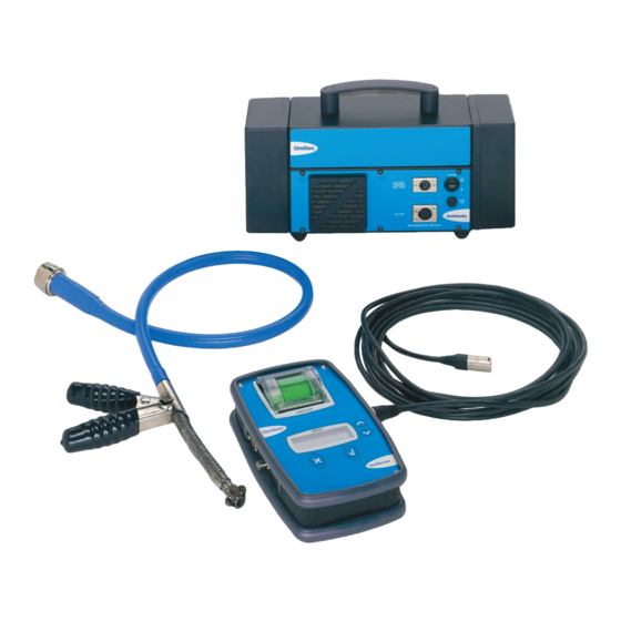
Introduction OmiSmoke Components Handset The handset displays the results from each test on the LCD. Progress through the tests is indicated on the LCD, while the 4 buttons allow for menu navigation and option selection. OM0381 1. Test results printer 2. - Page 7 Introduction There are 5 connectors located on the sides of the handset: OM0379 1. Engine oil temperature sensor connector 2. Engine RPM sensor (OmiSpeed) BNC connector 3. 9-pin D type VI Card reader input OM0380 1. Smokemeter 5-pin XLR connector 2.
-
Page 8: Smokemeter
Introduction Smokemeter The smokemeter houses the measurement components of OmiSmoke. OM0382 1. Receiver optics cover 2. Air intake 3. 4-pin XLR power connector 4. 5-pin XLR handset connector 5. Fuse 6. Power switch 7. Transmitter optics cover 8. Carry handle... - Page 9 Introduction OM0383 1. Exhaust smoke outlet 2. Exhaust sample probe input 3. Air knife vents Do not obstruct the air knife vents whilst running the OmiSmoke smokemeter. Note: The battery access cover is located on the underside of the smokemeter.
-
Page 10: Sample Hose
OM0384 The exhaust probe collects gas samples from the test vehicle exhaust, which are then analysed by OmiSmoke. Take care to avoid contact with the exhaust system when inserting or removing the sample hose. The exhaust system will be hot and severe... -
Page 11: Inserting Sample Hose Probe
Introduction Inserting sample hose probe Place the probe into the exhaust following the quick guide below: OM0478 The probe should never be placed directly behind a bend in the exhaust pipe or close to the silencer or expansion box. It should attach using the securing clamp, which will ensure a minimum insertion. -
Page 12: Engine Oil Temperature Sensor Probe
The engine temperature sensor probe measures engine oil temperature in the sump of the test vehicle, providing an accurate reading of the temperature of the engine. The probe connects to the OmiSmoke handset using the Oil Temperature Probe socket. To monitor the engine temperature of the vehicle after it’s warm-up period, prior to an emissions test, the sensor probe must be inserted into the engine oil dipstick aperture. -
Page 13: Setting The Sensor Probe Depth Gauge
Introduction Setting the sensor probe depth gauge OM0375 The sensor probe is fitted with a depth gauge to prevent the probe from being inserted too far (which could cause serious damage to the engine). Move the rubber sleeve on the probe, so that the distance between it and the end of the probe, is equal to the length of the dipstick (see illustration). -
Page 14: Safety Precautions
• DO NOT handle the OmiSmoke exhaust probe tip, or place the exhaust probe on plastic or combustible surfaces after the test procedure. The probe may become extremely hot during the test and could cause burns and a risk of fire. -
Page 15: Getting Started
Getting Started PC Based Systems Getting Started System requirements The minimum PC system requirements to load the OmiGas/OmiSmoke Techcenter software are: • Windows 98, ME, 2000 or XP • Pentium 133 processor or higher • 32 MB RAM • 10 MB of free disk space •... -
Page 16: Emissions Testing Using The Handset
Getting Started Emissions Testing Using the Handset OmiSmoke emissions testing can be undertaken by using the handset or a PC (using the OmiGas/OmiSmoke Techcenter software). Navigation through the emissions test software using the handset is assisted by the on-screen information and prompts which are displayed throughout the testing procedure. -
Page 17: Emissions Testing Using The Pc
OmiGas unit (OM4500/1). The PC system will need to recognise new hardware for the OmiSmoke. To achieve this, return to the main menu and select ‘ABORT’. The software will then re-establish communication and the message ‘Configuring Analyser - Please Wait’... -
Page 18: Pc Navigation Short-Cut Buttons
Select to print the data for the current emissions test. Select to access the OmiSmoke help files, if you need assistance or clarification during an emissions test. Select to close the OmiSmoke Techcenter program. An emissions test can... -
Page 19: Test Procedures
Test Procedures Preparation of Vehicle Prior to Tests Test Procedures This is a guidance note, similar to that which will be found in the Vehicle and Operator Services Agency (VOSA) inspection manual. Checks on Vehicle Before Tests As a general precaution, check: 1. -
Page 20: Mot Fas Test Procedure
The engine should be at idle before the start of each test. The OmiSmoke will automatically calculate a Pass or a Fail and print the result. From the Main Menu, the operator can select which test is required, by scrolling down the menu using the up and down buttons, and confirming the selection by pressing the tick key. -
Page 21: Category Of Vehicle
An RPM probe (analyser) can be used to establish engine speed and recognise a FAS test in progress. This is normally optional but may be necessary in some testing. OmiSpeed, part no. OM1600 is available from Omitec. Select from the following menu:... -
Page 22: Smart Card
OM0479 The introduction of MOT computerisation requires the use of a Smart Card to pass data to the OmiSmoke. A Smart Card reader is connected to the socket on the side of the handset, market ‘VI Interface’(9 pin D type). -
Page 23: Test Type
Test Procedures Using the up and down buttons start by scrolling through to find the character required for the first position. This will scroll 0-10 followed by A-Z with the up button or the reverse with the down button. Fill the entire fieldbox ‘[ ]’ to progress. Press the tick key to enter a blank. Spaces can be entered by also pressing the tick key. -
Page 24: Reduced Pollution Certificate (Rpc) - (Category B Only)
Test Procedures Reduced Pollution Certificate (RPC) - (Category B only) The RPC menu is only shown if category B has been selected previously. Select RPC 1, 2, 3, 4 or No RPC for standard MOT tests. RPC limits for 1, 2, 3 and 4 are explained in relevant RPC test instruction manual. - Page 25 Test Procedures Press the cross key for NO. By selecting ‘NO’ the OmiSmoke will impose a 40 second time penalty, showing a clear count down to this on the display. This period can be used to purge the engine and effectively prepare for the test.
-
Page 26: Insert Pipe Into Exhaust
Test Procedures Insert Pipe into Exhaust Place the probe into the exhaust following the quick guide below: OM0478 The probe should never be placed directly behind a bend in the exhaust pipe or close to the silencer or expansion box. It should attach using the securing clamp, which will ensure a minimum insertion. -
Page 27: Fas Test Procedure
The user should now be seated in the drivers seat with a handset or the PC screen in viewing distance, and follow the automated instructions: A schedule of up to 6 accelerations is automatically progressed by the OmiSmoke with automatic calculation of pass / fail status. It may also request another repeated acceleration if insufficient data was recorded. -
Page 28: Results And Print
Test Procedures Results and Print Once the OmiSmoke has achieved a result it will inform the user of ‘Waiting for smoke to disperse’. Fail result with oil temp. at >60°C and <80°C A fail report after a category A test and an oil temperature of greater than 60°C but less than 80°C, will not be produced and the user will be informed to raise the engine... - Page 29 Press the tick key and the display will show ‘Printed Results - Please Wait...’ The print should take approximately 10-15 seconds. A second set of results will be offered. The OmiSmoke will return to the main menu once the user has confirmed sufficient prints.
-
Page 30: Peak Test
Test Procedures Peak Test The OmiSmoke will make a continuous smoke reading and report the Peak K value. A reset button (X) is offered to reset the peak value during the diagnostic period. This test is useful for engine analysis during service repair or diagnostic work and can be of use prior to the MOT FAS test. -
Page 31: Peak Test Quick Summary Of Events
Test Procedures Peak Test Quick Summary of Events • Connect RPM - yes or no • Tube warm up to 70°C • Contamination - bench reset and optic zero check • Insert pipe into exhaust • Smoke peak reading given •... -
Page 32: Continuous Test
Test Procedures Continuous Test The OmiSmoke will make a continuous smoke reading and report the K value on a continuous basis. This test is useful for engine analysis during service repair or diagnostic work and can be of use over the whole engine speed range. This test will not hold the peak K value as would the Peak test. -
Page 33: Continuous Test Quick Summary Of Events
Test Procedures Continuous Test Quick Summary of Events • Connect RPM - yes or no • Tube warm up to 70ºC • Contamination - bench reset and optic zero check • Insert pipe into exhaust • Smoke continuous reading given •... -
Page 34: Linearity Test (Calibration Verification Check)
The ‘Calibration Validation Check’, known as ‘Linearity Check’ on the OmiSmoke, needs to be carried out every 7.5 days. The OmiSmoke prompts the user to carry out a ‘Linearity Check’ when calibration is due, alternatively the user can carry out the check on demand. - Page 35 Test Procedures If the linearity check fails, check the correct filter is being used and is inserted correctly before trying again. If repeat failure occurs, check filter is clean - See ‘Cleaning and Maintenance’ section. Once the linearity check is completed successfully, remove the filter and press the tick key to return to the main menu.
-
Page 36: Diagnostics
Test Procedures Diagnostics Diagnostics for the OmiSmoke are provided to help the user check over the status of the equipment as part of routine maintenance or as part of Helpdesk diagnostics should a problem be encountered. Smoke Head Info The ‘Smoke Head Details’ screen displays the following information, some of which... - Page 37 Test Procedures Heading Description User Notes Serial # Serial number of smoke head Customer code Customer code Part List Rev. Build parts list revision (issue number) Manufacturer Manufacturer Date Date Program Location Location of program S/Ware # Software number in smoke head S/W rev Software revision...
-
Page 38: Smoke Readings
Test Procedures Smoke Readings The ‘Smoke Readings’ screen displays the calculated K reading, percentage of opacity, acceleration detection, engine speed, battery voltage, tube temperature, heater status and the fan status. The following information is mainly for use in Helpdesk diagnostic. Reading Description User Notes... -
Page 39: Smoke Raw Data
Test Procedures Smoke Raw Data The ‘Smoke Raw Data’ screen displays the opacity reading, tube temperature and battery voltage. Reading Description User Notes Opacity 3 digit number - typically 444 with no filter or fault Tube Temp 3 digit number - typically 300 but can vary with tube temperature... -
Page 40: Printer Test
Test Procedures Printer Test The ‘Printer Test’ screen displays text under the ‘Print Data’ tab to enable the operator to check the printer for correct operation. This is automatic on selection and will print out the following as means of checking the operation of the printer. -
Page 41: Clock Setup Mode
Test Procedures Clock Setup Mode The Clock Setup Mode allows the user to change the internal clock to the correct time. Select ‘Clock Setup Mode’ from the main menu. The Clock Setting mode displays the current time in the main window. To change the time, press the tick key. -
Page 42: Calibration
Test Procedures Calibration The calibration menu is only available for use by authorised service/calibration engineers. -
Page 43: Cleaning And Maintenance
Cleaning and Maintenance Cleaning Cleaning and Maintenance Cleaning the smokemeter The smokemeter can be cleaned with a non-aggressive cleaner and a soft cloth. DO NOT immerse in water or use sprays of any kind. Ensure that the unit is switched off and disconnected before carrying out any cleaning on the smokemeter. -
Page 44: Cleaning Optics
OmiSmoke is used. The OmiSmoke will automatically inform the user when the optic signal is below recommended limits which will normally indicate that the optics will need cleaning. -
Page 45: Maintenance
Maintenance Calibration It is a requirement that the OmiSmoke is calibrated once a year, or as directed from time to time by the Vehicle inspectorate Executive Agency in the United Kingdom. This calibration must be carried out by UKAS approved engineers. -
Page 46: Troubleshooting
Troubleshooting OmiSmoke Error and Warning Messages Troubleshooting Symptom/ Fault Message Cause Action Blank handset Battery voltage Battery may screen too low or power require charging. not received by Attach external handset power supply/ charger. Check fuse and cable. Self test fail... - Page 47 Troubleshooting Symptom/ Fault Message Cause Action Smoke comms. Smoke Head Smoke head Contact Omitec error reported bad received bad Helpdesk command mode. command - Reset - Retry Communications Communications Check the fault with the problem with the handset cable smoke head.
- Page 48 Data on the smart Please contact the report failure to card is faulty. smart card/ reader helpdesk. helpdesk. Software error. Smart card Contact Omitec Report failure to received incorrect Helpdesk. meter message from manufacturer smoke meter Check details and Incorrect VRM or...
-
Page 49: Parts List
Parts List Spares Parts List The OmiSmoke has a number of spare parts and optional extras available from the manufacturer. Part Description Part Number Air Inlet Fan Filter FL5400A Battery BA1003A Category A Sample Probe and Hose OM1500/6 Category A Sample Probe Only... - Page 50 Omitec Instrumentation Ltd Hopton Industrial Estate London Road Devizes Wiltshire SN10 2EU United Kingdom Tel: +44 (0) 1380 732000 Fax: +44 (0) 1380 732001 email: sales@omitec.com Web: www.omitec.com...
Need help?
Do you have a question about the OmiSmoke and is the answer not in the manual?
Questions and answers