Table of Contents
Advertisement
Available languages
Available languages
NATURAL GAS MODELS:
PROPANE GAS MODELS:
SAFETY INFORMATION
WARNING
!
FIRE OR EXPLOSION HAZARD
Failure to follow safety warnings exactly
could result in serious injury, death, or
property damage.
- Do not store or use gasoline or other
fl ammable vapors and liquids in the vicinity of
this or any other appliance.
- WHAT TO DO IF YOU SMELL GAS:
•
Do not try to light any appliance.
•
Do not touch any electrical switch; do not
use any phone in your building.
•
Immediately call your gas supplier from a
neighbour's phone. Follow the gas
supplier's instructions.
•
If you cannot reach your gas supplier, call
the fi re department.
- Installation and service must be
performed by a qualifi ed installer, service
agency, or the supplier.
This appliance may be installed in an aftermarket,
permanently located, manufactured home (USA
only) or mobile home, where not prohibited by
local codes.
This appliance is only for use with the type of gas
indicated on the rating plate. This appliance is
not convertible for use with other gases, unless
a certifi ed kit is used.
INSTALLER:
Leave this manual with the appliance
CONSUMER:
Retain this manual for future reference
Wolf Steel Ltd., 24 Napoleon Rd., Barrie, ON, L4M 0G8 Canada / 103 Miller Drive, Crittenden, Kentucky, USA, 41030
Phone 1 (866) 820-8686 • www.napoleonfi replaces.com • hearth@napoleonproducts.com
$10.00
GX42NTRE
ADD PRODUCT CODE HERE (TRADE GOTHIC LT STD FONT)
GX42PTRE
INSTALLATION MANUAL
ADD MANUAL TITLE
CERTIFIED TO THE CANADIAN AND AMERICAN NATIONAL STANDARDS:
CSA 2.22 AND ANSI Z21.50 FOR VENTED DECORATIVE GAS APPLIANCES
IF INSTALLATION + OPERATION, ADD SERIAL
CSA /
INTERTEK
BARCODE LABEL ON THE OWNER'S MANUAL"
LOGO
Product Name / Code
(MUST use title from Price Book)
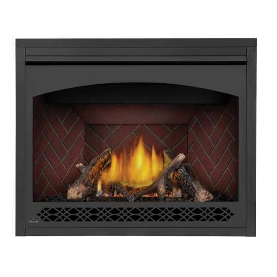
Ascent™ X 42
ADD ____ ILLUSTRATED
ADD PRODUCT IMAGE
FOR INDOOR USE ONLY
NUMBER LABEL HERE
PLACE BARCODE LABEL ON THE
IF SEPARATE MANUALS, ADD "PLACE
OWNER'S MANUAL
ENGLISH
FRENCH PG. 59
W415-1794 / 06.28.18
Advertisement
Chapters
Table of Contents

Related Manuals for Napoleon Ascent X 42 Series


Summary of Contents for Napoleon Ascent X 42 Series
- Page 1 OWNER’S MANUAL BARCODE LABEL ON THE OWNER’S MANUAL” LOGO Wolf Steel Ltd., 24 Napoleon Rd., Barrie, ON, L4M 0G8 Canada / 103 Miller Drive, Crittenden, Kentucky, USA, 41030 Phone 1 (866) 820-8686 • www.napoleonfi replaces.com • hearth@napoleonproducts.com $10.00 W415-1794 / 06.28.18...
- Page 2 safety information WARNING DANGER • This appliance is hot when operated and can cause severe burns if contacted. • Any changes or alterations to this appliance or its controls can be dangerous and is prohibited. HOT GLASS WILL CAUSE • Do not operate appliance before reading and BURNS.
- Page 3 patterns. safety information WARNING • Do not use a blower insert, heat exchanger insert or other accessory not approved for use with this appliance. • This appliance must not be connected to a chimney fl ue pipe serving a separate solid fuel burning appliance.
-
Page 4: Table Of Contents
table of contents general information gas installation rates and efficiencies nailing tab installation installation overview operation (electronic) rating plate information mobile home installation finish framing hardware list top vent front frame installation rear vent dimensions 10.0 finishing venting requirements 10.1 safety barrier &... -
Page 5: General Information
standard checklist Installer: please fill out appliance checklist in the owner’s manual 1.0 general information When the appliance is installed at elevations above 4,500ft (1372m), and in the absence of specific recommendations from the local authority having jurisdiction, the certified high altitude input rating shall be reduced at the rate of 4% for each additional 1,000ft (305m). -
Page 6: Installation Overview
general information installation overview Recommended installation steps: 1. Determine venting requirements before deciding the final location of the appliance. 2. Install rough framing (refer to “rough framing” section). 3. Place the appliance in its final position. 4. Install nailing tabs (refer to “nailing tab installation” section). 5. - Page 7 general information WARNING • Always light the pilot whether for the first time or if the gas supply has run out, with the glass door opened or removed. • Provide adequate clearance for servicing and operating the appliance. • Provide adequate ventilation. •...
-
Page 8: Rating Plate Information
Back 0” Arrière 0” L’appareil doit être ventilé à l’aide de l’ensemble d’évacuation propre à Napoleon. Référez au Vent top 3” Dessus du conduit d’évent 3” manuel d’installation pour les spécifications d’évacuation. Il est nécessaire de bien réinstaller et Vent sides &... -
Page 9: Hardware List
general information hardware list Ref. # Description Quantity Self-drilling screw 1/4” Hex, 1/2” long sheet metal screw 2 1/2” long sheet metal screw Quad drive sheet metal screw Sheet metal screw Pan head quad screw note: Only fasteners supplied with the appliance will be illustrated. front frame installation #2 X6 Install the front frame using 6 screws... -
Page 10: Dimensions
general information dimensions W415-1794 / 06.28.18... -
Page 11: Venting Requirements
venting requirements 2.0 venting requirements WARNING • Risk of fi re. Maintain specifi ed air space clearances to vent pipe and appliance. • The vent system must be supported every 3’(0.9m) for both vertical and horizontal runs. Use support ring assembly W010-0067 or equivalent non-combustible strapping to maintain the minimum clearance to combustibles for both vertical and horizontal runs. - Page 12 This template must be used in conjunction with templates 7.2.1 or 7.2.2, depending on termina- tion shape (i.e. round, or round and square). See appropriate templates folder. venting requirements For optimum fl ame appearance and appliance performance, keep the vent length and number of elbows to a minimum.
-
Page 13: Typical Venting Installation
venting requirements typical venting installation 24” (61cm) Maximum 20” (50.8cm) Maximum 12” (30.5cm) Minimum base of air collar 45 5/8” (115.8cm) Minimum plus rise* 24 3/16” (61.4cm) Minimum plus rise* TOP VENT REAR VENT Special vent installation (periscope termination) Use the periscope kit to locate the air termination above grade. The periscope must be installed so that when final grading is completed, the bottom air slot is located a minimum 12”... -
Page 14: Corner Termination
venting requirements 12” 16" (40.6cm) 12” MINIMUM minimum MINIMUM 30” MINIMUM MAXIMUM 10FT VENT LENGTH 40 FT (12M) INSTALLATION REAR EXIT INSTALLATION maximum 3 FT (1M) minimum 12” 0.8cm) 6” (152mm) MINIMUM RISE MINIMUM 30” base of air collar 30” MINIMUM MINIMUM 2.1.1 corner termination... -
Page 15: Minimum Air Terminal Location Clearances
venting requirements minimum air terminal location clearances Covered balcony applications ††* ≤ 15 feet = 3 feet = 2 x ACTUAL (0.9m) (4.6m) note: INSTALLATIONS Wall terminals are for illustration purposes only. Size and shapes may vary. CANADA U.S.A. 12” (30.5cm) 12”... -
Page 16: Top Exit - All Terminations
venting requirements top exit - all terminations 40’ V+H ≤ 40 ft. (For longer vent runs, a power 38 1/2’ vent is required). (462”) H ≤ 20 ft. V + H are measured from the centre of vent elbows. Elbows are considered as 90º. Two 45º... -
Page 17: Rear Exit - Horizontal Termination
venting requirements rear exit - horizontal termination (For vent runs that exceed the graph 40’ parameters, a power vent is required). V + H are measured from the centre of vent elbows. Elbows are considered as 90º. Two 45º elbows = One 90º elbow. 35 3/4’... -
Page 18: Rear Exit - Vertical Termination
venting requirements rear exit - vertical termination (For vent runs that exceed the graph 40’ parameters, a power vent is required). 39’ V + H are measured from the centre of vent (468”) elbows. Elbows are considered as 90º. Two 45º elbows = One 90º elbow. 1-6 elbow zone 1-5 elbow zone 1-4 elbow zone... -
Page 19: Rear Exit
venting requirements rear exit WARNING • Failure to create a seal to the fi rebox with the exhaust collar assembly will cause the appliance to function improperly and can cause injury or property damage. Remove the safety barrier and glass front (see "safety barrier &... -
Page 20: Top Exit
venting requirements top exit WARNING • Failure to create a seal to the fi rebox with the exhaust collar assembly will cause the appliance to function improperly and can cause injury or property damage. note: This appliance has been factory shipped as a rear vent. Remove the safety barrier and glass door (see "safety barrier &... -
Page 21: Rough Framing
rough framing 3.0 rough framing note: When using optional fi nishing accessories, the framing dimensions and fi nishing materials may differ from what is outlined in the section below; refer to the leafl et instructions supplied in the accessory kit for specifi c framing and fi nishing specifi cations. -
Page 22: Minimum Clearance To Combustible Enclosures
rough framing minimum clearance to combustible enclosures note: Vent Sections When passing through a wall, use firestop spacer W615-0162 (supplied). When passing through a ceiling, use firestop spacer W500-0096 (not supplied). Top Vent 3” (76.2mm) Minimum** 3” (76.2mm)** 3” min. 8”... - Page 23 rough framing Minimum Rear Vent Clearances For rear vent termination not exceeding 10" (254mm) of horizontal vent run. 72” 8” (203mm) (183cm) non- Ceiling (min.) combustible material 52” (132.cm) 41 1/8” (104.5cm) 24 3/16” (61.4cm) Minimum plus rise* Horizontal vent sections: A minimum clearance of 3” (76mm) on the top outside of the enclosure and 1” (25mm) on the sides and bottom outside of the enclosure all around the vent pipe on all horizontal runs to com- bustibles is required.
- Page 24 rough framing Maximum Rear Vent Clearances (Example 1) For rear vent termination exceeding 10" (254mm). 8” (203mm) non- combustible material 52” (132.1cm) 41 1/8” (104.5cm) 24 3/16” (61.4cm) Minimum plus rise* Horizontal vent sections: A minimum clearance of 3” (76mm) on the top outside of the enclosure and 1” (25mm) on the sides and bottom outside of the enclosure all around the vent pipe on all horizontal runs to com- bustibles is required.
- Page 25 rough framing Maximum Rear Vent Clearances (Example 2) 8” (203mm) non- combustible material 52” (132.1cm) 41 1/8” min. (104.5cm) 24 3/16” (61.4cm) Minimum plus rise* Horizontal vent sections: A minimum clearance of 3” (76mm) on the top outside of the enclosure and 1” (25mm) on the sides and bottom outside of the enclosure all around the vent pipe on all horizontal runs to com- bustibles is required.
- Page 26 rough framing note: For heavier finishing materials such as marble, we recommend adding extra support to the frame. Ensure there is adequate floor support for the appliance and finishing material. Before framing your appliance, determine vent requirements before deciding the final location of the appliance. After rough framing, place the appliance in its final position.
-
Page 27: Venting Installation
4.0 venting installation venting installation WARNING • Ensure to unpack all loose materials from inside the fi rebox prior to connecting the gas and electrical supply • If your appliance is supplied with a remote, ensure the remote receiver is in the “OFF” position prior to connecting the gas and electrical supply to the appliance. -
Page 28: Vertical Installation
venting installation vertical installation This application occurs when venting through a roof. Installation kits for various roof pitches are available from your authorized dealer / distributor. See the “accessories” section to order specifi c kits required. A. Determine the air terminal location, cut and frame a square opening, as illustrated, in the ceiling and the roof to provide the minimum 1"... -
Page 29: Using Either Flexible Vent Components
venting installation using either flexible vent components WARNING • Do not allow the inner fl ex pipe to bunch up on horizontal or vertical runs and elbows. Keep it pulled tight. • Spacers are attached to the inner fl ex pipe at predetermined intervals to maintain an even air gap to the outer fl ex pipe. -
Page 30: Vertical Air Terminal Installation
venting installation 4.3.2 vertical air terminal installation WARNING • Maintain a minimum 2” (51mm) space between the air inlet base and the storm collar. note: Fastening hardware provided with appropriate roof terminal and liner kits. Fasten the roof support to the roof using 6 screws. The roof support is optional. -
Page 31: Restricting Vertical Vents
venting installation 4.3.4 restricting vertical vents WARNING • Turn off gas and electrical supply before servicing the appliance. • Appliance may be hot, do not service until appliance is cool. • For safe and proper operation of the appliance, follow the venting instruction exactly. •... -
Page 32: Electrical Information
5.0 electrical information venting installation hard wiring connection It is necessary to hard wire this appliance. This appliance must be electrically connected and grounded in accordance with local codes. In the absence of local codes, use the current CSA C22.1 Canadian Electrical Code in Canada or the ANSI/NFPA 70-1996 National Electrical Code in the United States. -
Page 33: Battery Back-Up Installation
electrical information battery back-up installation WARNING • Ensure the gas and electrical power to the appliance is turned off. • Appliance may be hot, do not service until the appliance has cooled. note: In the event of a power failure, your appliance can be operated using the supplied battery back-up. Before beginning installation, turn off the gas and disconnect the electrical power supply from the appliance. -
Page 34: Wiring Diagram
electrical information wiring diagram WARNING • Do not wire 110 volts to the valve or wall switch. note: This appliance comes equipped with a battery back-up. If this back-up is used, install 4 ‘AA’ batteries (not supplied) into the holder and connect to the wire harness. Connect the battery holder to the wire harness before using the appliance. -
Page 35: Gas Installation
6.0 gas installation electrical information WARNING • Risk of fi re, explosion, or asphyxiation. Ensure there are no ignition sources such as sparks or open fl ames. • Support gas control when attaching gas supply pipe to prevent damaging gas line. •... -
Page 36: Operation (Electronic)
8.0 operation (electronic) operation WARNING • If you do not follow these instructions exactly, a fi re or explosion may result causing property damage, personal injury, or loss of life. • If applicable, always light the pilot whether for the fi rst time or if the gas supply has run out with the glass door opened or removed. -
Page 37: Finish Framing
finish framing 9.0 finish framing top vent WARNING • Risk of fire! • Maintain all specified air space clearances to combustibles. Failure to comply with these instructions may cause a fire or cause the appliance to overheat. • Ensure all clearances (i.e. back, side, top, vent, mantel, front, etc.) are clearly maintained. Ceiling 72”... -
Page 38: Rear Vent
finish framing rear vent WARNING • Risk of fire! • Maintain all specified air space clearances to combustibles. Failure to comply with these instructions may cause a fire or cause the appliance to overheat. • Ensure all clearances (i.e. back, side, top, vent, mantel, front, etc.) are clearly maintained. Ceiling 72”... -
Page 39: Finishing
finishing 10.0 finishing WARNING • Risk of fire! • Never obstruct the front opening of the appliance. • The front of the appliance must be finished with any non-combustible materials such as brick, marble, granite, etc., provided that these materials do not go below the specified dimension, as illustrated. •... -
Page 40: Front Hood Installation
finishing 10.2 front hood installation note: This hood must be installed, if it has not already been factory installed. Safety door and screen must be removed. Remove the securing screws from the top of the firebox, as shown. Install the front hood, ensure it is angled downward when installed. Reinstall the previously removed securing screws. -
Page 41: Installing Non-Combustible Board
finishing 10.3 installing non-combustible board WARNING Non-combustible facing material must not project more than 4” (101.6mm) from the face of the door (all four sides). If greater projections are desired, increase the clearance to the sides, bottom and top by 2” (50.8mm) for every additional 1”... -
Page 42: Minimum Combustible Mantel Clearances
finishing 10.4 minimum combustible mantel clearances Combustible Mantel clearance can vary according to the mantel depth. Use the graph to help evaluate the clear- ance needed. MANTEL DEPTH Appliance Opening MANTEL DIMENSIONS Height Depth 29 5/8” (75.2cm) 8" (20.3cm) 2" (51mm) 10"... -
Page 43: Log Placement
The logs are fragile and should be handled with care. Air Cover Air Cover PHAZER™ logs and glowing embers, exclusive to Napoleon, provide a unique and realistic glowing effect that is dif- Air Cover Air Cover INSERT PHAZER™ LOGS AND GLOWING EMBERS STATEMENT IF APPLICABLE: ferent in every installation. - Page 44 finishing Bottom Cutout Bottom Cutout Bumpout Bumpout Bumpout Bumpout Notch Notch Notch Notch Bottom Cutout Bottom Cutout Bumpout Bumpout Bumpout Bumpout Place the bumpout on log #3 (W135-0762) into Place the bumpout on log #4 (W135-0763) into Notch Notch Notch Notch PLACE TEXT BOX HERE.
-
Page 45: Glowing Embers
finishing 10.7 glowing embers Tear the embers into pieces and place along the front row of ports covering all of the burner area in front of the small logs. Care should be taken to shred the embers into thin, small irregular pieces as only the exposed edges of the fibre hairs will glow. -
Page 46: Adjustments
11.0 adjustments adjustments 11.1 restricting vertical vents Vertical installations may display a very active fl ame. If this appearance is not desirable, the vent exit must be restricted using a restrictor vent kit. Refer to the “replacement parts” section of the owner’s manual for the appropriate kit. -
Page 47: Pilot Burner Adjustment
adjustments 11.3 pilot burner adjustment Adjust the pilot screw to provide properly sized fl ame. Turn in a clockwise direction to reduce the gas fl ow. Check Pressure Readings: Inlet pressure can be checked by turning screw (A) counter- ODS - MILLIVOLT clockwise 2 or 3 turns and then placing pressure gauge tubing over the test point. -
Page 48: Maintenance
12.0 maintenance adjustments WARNING • Turn off the gas and electrical power before servicing the appliance. • Appliance may be hot. Do not service until appliance has cooled. • Do not use abrasive cleaners on glass. • Do not paint the pilot assembly. This appliance and its venting system should be inspected before use and at least annually by a qualifi ed service person. -
Page 49: Annual Maintenance
maintenance This appliance is factory equipped with 5mm ceramic glass. Use only replacement parts as supplied by the appliance manufacturer. DO NOT SUBSTITUTE MATERIALS. 12.2 annual maintenance WARNING • Annual maintenance should be performed by a qualifi ed service technician •... -
Page 50: Replacement Parts
replacement parts 13.0 replacement parts WARNING • Failure to position the parts in accordance with this manual or failure to use only parts specifi cally approved with this appliance may result in property damage or personal injury. Contact your dealer for questions concerning prices and policies on replacement parts. Normally, all parts can be ordered through your Authorized dealer / distributor. -
Page 51: Overview
replacement parts W415-1794 / 06.28.18... -
Page 52: Valve Train Assembly
replacement parts W415-1794 / 06.28.18... -
Page 53: Troubleshooting
14.0 troubleshooting troubleshooting WARNING • Always light the pilot whether for the fi rst time or if the gas supply has run out, with the glass door open or removed. • Turn off gas and electrical power before servicing the appliance. •... - Page 54 troubleshooting symptom problem test solution Pilot will not light. Makes Wiring: short, loose, or damaged Verify the thermocouple/sensor is clean and the wiring is undamaged. Verify the interrupter block is not damaged or too tight. Verify noise with no spark at connections connections from pilot assembly are tight;...
- Page 55 Wire connector pins are bent. Straighten pins. Valve wiring is damaged. Replace valve. troubleshooting symptom problem test solution Motor is turning, Receiver batteries low. Replace batteries. frequent beeping occurs. Lights or blower Control module switch in Verify ON/OFF switch is in the “I” position which denotes on. won’t function (if wrong position.
-
Page 56: Warranty
President’s Limited Lifetime Warranty Policy are subject to a single claim. During the fi rst 10 years Napoleon will replace or repair the defective parts covered by the lifetime warranty at our discretion free of charge. From 10 years to life, Napoleon will provide replacement parts at 50% of the current retail price. All parts replaced under the warranty will be covered for a period of 90 days from the date of their installation. - Page 57 notes 29.1 W415-1794 / 06.28.18...
- Page 58 NAPOLEON CELEBRATING OVER 40 YEARS OF HOME COMFORT PRODUCTS 7200, Route Transcanadienne, Montréal, Québec H4T 1A3 24 Napoleon Road, Barrie, Ontario, Canada L4M 0G8 214 Bayview Drive, Barrie, Ontario, Canada L4N 4Y8 103 Miller Drive, Crittenden, Kentucky, USA 41030 Phone: 1-866-820-8686...
- Page 59 SUR LE MANUEL DU PROPRIÉTAIRE LOGO BARCODE LABEL ON THE OWNER’S MANUAL” Wolf Steel Ltd., 24 Napoleon Rd., Barrie, ON, L4M 0G8 Canada / 103 Miller Drive, Crittenden, Kentucky, USA, 41030 Téléphone 1(866)820-8686 • www.napoleonfoyers.com • hearth@napoleonproducts.com $10.00 W415-1794 / 06.28.18...
- Page 60 NEVER ALLOW CHILDREN TO TOUCH GLASS. A barrier designed to reduce the risk of burns from the consignes de sécurité hot viewing glass is provided with this appliance and shall be installed for the protection of children and other AVERTISSEMENT at-risk individuals.
- Page 61 continue de s’éteindre, faire réparer. Garder propres le brûleur et le compartiment de contrôle. • Cet appareil ne devra être modifi é en aucun cas. • Ne laissez pas les ventilateurs souffl er directement sur l’appareil. Empêchez les courants d’air de modifi er consignes de sécurité...
- Page 62 table des matières information générales information électriques taux et efficacités branchement par câble vue d’ensemble de l’installation schéma de câblage du réceptacle information sur la plaque d’homologation schéma de câblage électronique installation du sauvegarde de pile installation dans une maison mobile schéma câblage liste des pièces branchement du gaz...
-
Page 63: Taux Et Efficacités
liste de vérification Installateur: veuillez remplir la liste de contrôle de l’appareil dans le manuel du propriétaire. 1.0 information générales Lorsque l’appareil est installé à une altitude de plus de 4 5000 pieds (1372m) et en l’absence de recommandations particulières de l’autorité compétente locale, l’indice certifié du débit à haute altitude devra être réduit au taux de 4% pour chaque 1 000ft (305m) supplémentaire. -
Page 64: Information Générales
information générales vue d’ensemble de l’installation Étapes d’installation recommandés: 1. Déterminer les exigences de ventilation avant de décider de l’emplacement final de l’appareil. 2. Installez l’encadrement approximatif (référez à la section « encadrement approximatif »). 3. Placez l’appareil dans sa position finale. 4. - Page 65 information générales AVERTISSEMENT • Allumez toujours la veilleuse, que ce soit pour la première fois ou lorsque l’approvisionnement en gaz est épuisé, avec la porte vitrée ouverte ou retirée. • Prévoyez un accès suffisant pour entretenir et opérer l’appareil. • Assurez-vous d’une quantité...
-
Page 66: Information Sur La Plaque D'homologation
Back 0” Arrière 0” L’appareil doit être ventilé à l’aide de l’ensemble d’évacuation propre à Napoleon. Référez au Vent top 3” Dessus du conduit d’évent 3” manuel d’installation pour les spécifications d’évacuation. Il est nécessaire de bien réinstaller et Vent sides &... -
Page 67: Liste Des Pièces
information générales liste des pièces Réf. Description Quantité Vis autotaraudeuses 1/2” vis long de feuille métallique 2/12” vis long de feuille métallique Vis de feuille métallique (quad) Vis de feuille métallique #10-32 x 5/8” Pan Hd Quad note: Seulement les attaches fournies avec l’appareil sont illustrées. installation de la cadre supérieure #2 X6 Install the front frame using 6 screws... - Page 68 information générales dimensions W415-1794 / 06.28.18...
- Page 69 2.0 exigences d’évacuation exigences d'évacuation AVERTISSEMENT • Risque d’incendie. Conservez les dégagements nécessaires au conduit d’évent et à l’appareil. • Les courses horizontales et verticales du système doivent être supportées à tous les 3 pi (0,9m). Utilisez des supportes ou des attaches incombustibles équivalents afi n de maintenir le dégagement aux matériaux combustibles pour les courses verticales et horizontales.
-
Page 70: Exigences D'évacuation
du conduit extérieur de prise d’air doivent être scellés avec un scellant de silicone rouge à haute temp3rature (RTV). Ce même scellant peut être utilisé sur les joints des conduits intérieurs et extérieurs de tous les autres systèmes d’évents approuvés à l’exception du raccordement du conduit d’évacuation à la buse de l’appareil qui exigences d'évacuation doit être scellé... -
Page 71: Installation Typiques
exigences d'évacuation installation typiques 24” (61cm) Maximum 20” (50.8cm) Maximum 12” (30,5cm) Minimum base du collier d’air 45 5/8” (115.8cm) Minimum plus la pente* 24 3/16” (61.4cm) Minimum plus la pente Évacuation Évacuation dessus arrière Installations particulières d’évents (terminaison périscopique) Utilisez l’ensemble périscopique afin de positionner la terminaison au-dessus du niveuau du sol. -
Page 72: Installation En Coin
exigences d'évacuation 16" (40.6cm) minimum 40 ft (12m) Maximum 3 ft (1m) minimum 12” 12” MINIMUM 12” MINIMUM MINIMUM 30” Base du collier d’air 30” MINIMUM 30” MINIMUM MINIMUM 2.1.1 installation en coin MAXIMUM 10FT VENT LENGTH MAXIMUM 10FT VENT LENGTH Lorsque l’évent est installé... -
Page 73: Emplacements Et Dégagements Minimaux De La Terminaison
exigences d'évacuation emplacements et dégagements minimaux de la terminaison Applications pour balcon couvert ††* = 3 feet ≤ 15 feet = 2 x ACTUAL (0.9m) (4.6m) note: INSTALLATIONS Les terminaux du mur sont à des fi ns d’illustration seulement. La taille et les formes peuvent varier. CANADA É.-U. -
Page 74: Évacuation Dessus - Toutes Terminaisons
exigences d'évacuation évacuation dessus - toutes terminaisons 40’ V+H≤ 40 ft. (Pour les courses d’évacuation plus V+H ≤ 40 ft. (For longer vent runs, a power 38 1/2’ longues, un évent de puissance est nécessaire) vent is required). (462”) H ≤20 ft. H ≤... -
Page 75: Évacuation Dessus - Terminaison Horizontale
exigences d'évacuation évacuation dessus - terminaison horizontale (For vent runs that exceed the graph Pour les courses d’évacuation plus longues, un évent 40’ de puissance est nécessaire parameters, a power vent is required). V + H sont mesurés à partir du centre des coudes de V + H are measured from the centre of vent ventilation. -
Page 76: Évacuation Arrière - Terminaison Verticale
exigences d'évacuation évacuation arrière - terminaison verticale Pour les courses d’évacuation plus longues, un évent (For vent runs that exceed the graph 40’ de puissance est nécessaire parameters, a power vent is required). 39’ V + H sont mesurés à partir du centre des coudes de V + H are measured from the centre of vent (468”) ventilation. -
Page 77: Évacuation Arrière
exigences d'évacuation évacuation arrière AVERTISSEMENT • Omettre de créer un scellant à la chambre de combustion avec l’assemblage du collet d’évacuation d’air causera l’appareil de fonctionner incorrectement et pourrait causer des clessures ou des dommages matériels. Fig. 1 Enlever la barrière de protection et la porte vitrée, référez la section «... -
Page 78: Évacuation Dessus
exigences d'évacuation évacuation dessus AVERTISSEMENT • Il est essentiel que le couvercle d'évacuation soit installé, si non, l'appareil ne fonctionnera pas correcte- ment et pourrait causer des blessures ou des dommages matériels. Cette appareil a été expédié avec une évacuation à l'arrière. Enlevez l'écran de protection et vitre de la porte (voir la section «... -
Page 79: Encadrement Approximatif
encadrement approximatif 3.0 encadrement approximatif note: Lorsque vous installez les accessoires de fi nition optionelles, les dimensions de l’ossature et les matériaux de fi nition peuvent différer de ce qui est décrit dans ces instructions ci-dessous, voir les instructions fournies dans le trousse de l’accessoire pour les spécifi cations détaillées. -
Page 80: Dégagements Minimaux Aux Enceintes Combustibles
encadrement approximatif dégagements minimaux aux enceintes combustibles note: Sections d’évents Lors du passage à travers un mur, utiliser l’espaceur coupe-feu W615-0612 (fourni). Lors du passage à travers un plafond, utiliser l’espaceur coupe-feu W500-0096 (non fourni). Évacuation sur le dessus 3” (76,2mm) Minimum** 3”... - Page 81 encadrement approximatif Dégagements minimaux d’évacuation à l’arrière Pour les applications de terminaison d’évacuation arrière qui ne dépassent pas 10" (254mm) du course d’évacuation horizontale. 8” 72” (203mm) (183cm) au non- plafond (min.) combustible material 52” (132,1cm) 41 1/8” (104,5cm) 24 3/16” (61,4cm) Minimum plus la pente*...
- Page 82 encadrement approximatif Dégagements maximum d’évacuation à l’arrière (Exemple 1) Pour l’évacuation arrière qui dépassent 10" (254mm). 8” (203mm) matériau incombustible 52” (132.1cm) 41 1/8” (104,5cm) 24 3/16” (61.4cm) Minimum plus la pente* Sections d’évents horizontales: Un dégagement minimum aux matériaux combustibles de 3” (76mm) au- dessus hors de l’enceinte et 1”...
- Page 83 encadrement approximatif Dégagements maximum d’évacuation à l’arrière (Exemple 2) 8” (203mm) matériau incombus- tible 52” (132.1cm) 41 1/8” min. (104,5cm) 24 3/16” (61,4cm) Minimum plus la pente* Sections d’évents horizontales: Un dégagement minimum aux matériaux combustibles de 3” (76mm) au- dessus hors de l’enceinte et 1”...
- Page 84 encadrement approximatif note: Pour les matériaux de finition plus lourds comme du marbre, nous vous recommandons d’ajouter un support additionnel à l’ossature. Assurez-vous que le support de plancher est adéquat pour l’appareil et le matériau de finition. Avant d’encadrer votre appareil, déterminez les exigences d’évacuation avant de décider de l’emplacement final de l’appareil.
-
Page 85: Installation D'évacuation
4.0 installation d’évacuation installation d’évacuation AVERTISSEMENT • Avant d’effectuer les branchements pour l’alimentation en gaz et électronique, assurez-vous de retirer toute composante non fi xée à l’intérieur de la chambre de combustion. • Si votre appareil comprend un système de télécommande, assurez-vous que le récepteur est à la position «... -
Page 86: Installation Verticale
installation d’évacuation installation verticale Cette confi guration s’applique lorsque l’évacuation se fait à travers un toit. Des ensembles d’installation pour les différentes pentes de toit sont disponibles chez votre détaillant autorisé. Voir la section « accessoires » dans le manuel du propriétairepour commander l’ensemble spécifi que dont vous avez besoin. -
Page 87: Utilisation De Composants D'évacuation Flexible
installation d’évacuation utilisation de composants d’évacuation flexible AVERTISSEMENT • Ne laissez pas la gaine fl exible se tasser contre les courses horizontales ou verticales et les coudes. Gardez-la tendue. • Des espaceurs sont fi xés à la gaine fl exible à intervalles prédéterminés afi n de garder un espace vide avec le conduit extérieur. -
Page 88: Installation De La Terminaison Verticale
installation d’évacuation 4.3.2 installation de la terminaison verticale AVERTISSEMENT • Conservez un espace minimale de 2 po (51mm) entre la base de la prise d’air et le collet de solin. Matériel de fi xation fourni avec les ensembles de terminal pour toit et raccord appropriées. Fixez le support de toit au toit à... -
Page 89: Renstreignant Des Évents Verticaux
installation d’évacuation 4.3.4 renstreignant des évents verticaux AVERTISSEMENT • Mettez hors tension de gaz et de l’alimentation électrique avant d’intervenir sur l’appareil. • Appareil peut être chaud, pas de service jusqu’à ce que l’appareil est refroidi. • Pour utilisation sûre et correcte de l’appareil, suivez les instructions d’évacuation exactement. •... -
Page 90: Information Électriques
5.0 information électriques information électriques branchement par câble It is necessary to hard wire this appliance. Vous devez effectuer un branchement par câble avec cet appareil. Une charpente permanente servant à encastrer l’appareil nécessite un branchement par câble de la boîte de dérivation de l’appareil. -
Page 91: Installation Du Sauvegarde De Pile
information électriques installation du sauvegarde de pile AVERTISSEMENT • Assurez-vous que l’alimentation électrique et du gaz sont éteints. • Assurez-vous que l’appareil est complètement refroidi avant de commencer service. note: En cas d’une panne de courrant, votre appareil peut fonctionner utilisant le sauvegarde de pile fourni. Avant de commender l’installation, coupez l’alimentation électrique et clé. -
Page 92: Schéma Câblage
information électriques schéma câblage AVERTISSEMENT • Ne raccordez pas l’interrupteur mural ou la soupape de gaz à l’alimentation électrique (110V). note: Cet appareil est équipé avec un sauvegarde de pile. Si le sauvegarde de pile est utiliser, installez 4 piles « AA »... -
Page 93: Branchement Du Gaz
6.0 branchement du gaz branchement du gaz AVERTISSEMENT • Risque d’incendie, d’explosion, ou d’asphyxie. Assurez-vous qu’il n’y ait aucune source d’allumage comme des étincelles ou une fl amme nue. • Soutenez le contrôle du gaz lorsque vous attachez le tuyau pour éviter de plier la conduite de gaz. •... -
Page 94: Opération (Électronique)
opération (électronique) 8.0 opération (électronique) AVERTISSEMENT • Si ces instructions ne sont pas suivies à la lettre, un incendie ou une explosion pourraient s’ensuivre, causant des dommages matériels, des blessures corporelles ou des pertes de vie. • Si applicable, allumez toujours la veilleuse, que ce soit pour la première fois ou lorsque l’approvisionnement en gaz est épuisé, avec la porte vitrée ouverte ou retirée. -
Page 95: Encadrement Fini
encadrement fini 9.0 encadrement fini évacuation dessus AVERTISSEMENT • Risque d’incendie! • Conservez tous les dégagements aux matériaux combustibles spécifiés. Ne pas respecter ces instructions peut causer un incendie ou une surchauffe. • Assurez-vous que tous les dégagements (arrière, côtés, dessus, évents, tablette, façade, etc.) sont respectés à... -
Page 96: Évacuation Arrière
encadrement fini évacuation arrière AVERTISSEMENT • Risque d’incendie! • Conservez tous les dégagements aux matériaux combustibles spécifiés. Ne pas respecter ces instructions peut causer un incendie ou une surchauffe. • Assurez-vous que tous les dégagements (arrière, côtés, dessus, évents, tablette, façade, etc.) sont respectés à... -
Page 97: Finition
finition 10.0 finition AVERTISSEMENT • Risque d’incendie! • N’obstruez jamais l’ouverture sur le devant de l’appareil. • Si la finition de la façade de l’appareil est fait, elle doit être faite de matériau incombustible comme de la brique, du marbre du granite, etc., sous réserve que ces matériaux ne dépassent pas le dimension spécifiée, comme illustré. -
Page 98: Installation De L'hotte Avant
finition 10.2 installation de l’hotte avant note: Cette hotte doit être installée, si elle n’est pas déjà installée. La porte et l’écran de protection doivent être enlevés. Retirer les vis de fixation de la partie supérieure de l’appareil, comme illustré. Installez l’hotte avant, assurez-vous qu’elle est inclinée vers le bas lorsqu’elle est installée. -
Page 99: Installation Du Panneau Incombustible
finition 10.3 installation du panneau incombustible AVERTISSEMENT Les matériaux de finition incombustibles ne doivent pas dépasser de plus 4” (101,6mm) la façade de la porte (sur toutes côtés). Si des projections plus grandes sont requises, augmentez les dégagements des côtés et du dessus de 2"... -
Page 100: Dégagements Minimaux De La Tablette Combustible
finition 10.4 dégagements minimaux de la tablette combustible Le dégagement d’une tablette combustible à l’appareil peut varier selon la profondeur de la tablette. Utilisez le graphique pour vous aider à déterminer les dégagements nécessaire. PROJECTION DE LA TABLETTE (") DIMENSIONS DE LA TABLETTE Appliance Opening Réf... -
Page 101: Disposition Des Bûches
52.1.1 FOR NAPOLEON 52.1.2 FOR CONTINENTAL finition WARNING 10.6 disposition des bûches note: Log numbers are located on the bottom or back of the logs. • Failure to position the logs in accordance with these diagrams or failure to use only logs specifi cally approved AVERTISSEMENT with this appliance may result in property damage or personal injury. - Page 102 Burner Overview Découpe du Bas finition Découpe du Bas Bumpout Bumpout Bumpout Bumpout Encoche Encoche Encoche Encoche Découpe du Bas Découpe du Bas Bumpout Bumpout Bumpout Bumpout Encoche Encoche Encoche Placez le bumpout sur bûche #3 (W135- PLACE TEXT BOX HERE. Placez le bumpout sur bûche #4 (W135- PLACE TEXT BOX HERE.
-
Page 103: Braises Incandescentes
finition 10.7 braises incandescentes Déchirez les braises incandescentes en morceaux et placez-les le long de la première rangée des orifices du brûleur en couvrant toute la surface à l’avant des petites bûches. Les braises devraient être déchirées très soigneusement en petits morceaux minces irréguliers, car seuls les côtés exposés des fibres deviendront incan- descentes. -
Page 104: Ajustements
finition 11.0 ajustements 11.1 renstreignant des évents verticaux Certaines confi gurations d’évacuation verticales peuvent avoir une fl amme très active. Si cette apparence n’est pas désirée, la sortie du conduit d’évacuation doit être réduite en utilisant une plaque de restriction. Pour obtenir l’ensemble approprié, voir la section «... -
Page 105: Réglage De La Veilleuse
ajustements 11.3 réglage de la veilleuse Ajustez la vis de la veilleuse pour obtenir une fl amme de taille normale. Tournez vers la droite pour réduire l’apport de gaz. Vérifi ez la pression: Pour vérifi er la pression d’arrivée, tournez la vis (A) vers la gauche deux à... -
Page 106: Entretien
12.0 entretien entretien AVERTISSEMENT • Coupez l’alimentation en gaz et l’alimentation électrique avant de procéder à l’entretien de l’appareil. • L’appareil peut être chaud. Attendez qu’il soit refroidi avant d’en faire l’entretien. • N’utilisez pas de produits abrasifs. • Ne peinture pas l’assemblage de la veilleuse. Cet appareil et son système d’évacuation devraient être inspectés avant la première utilisation et au moins une fois l’an par un technicien de service qualifi é. -
Page 107: Entretien Annuel
entretien L’appareil est muni d’une 5mm en verre céramique Remplacez uniquement avec une pièce pour le foyer disponible chez votre détaillant autorisé. N’UTILISEZ PAS DE MATÉRIAUX SUBSTITUTS. 5.1.3 12.2 entretien annuel AVERTISSEMENT • Le caisson devient trés chaud lors du fonctionnement. Laissez l’appareil se refroidir complétement ou portez des gants antichaleur avant d’effectuer l’entretien. -
Page 108: Pièces De Rechange
13.0 pièces de rechange pièces de rechange AVERTISSEMENT • Omettre de positionner les pièces conformément à ce manuel ou d’utiliser uniquement des pièces spécifi quement approuvées pour cet appareil peut causer des dommages matériels ou des blessures corporelles. Contactez votre détaillant pour les questions concernant les prix et la disponibilité des pièces de remplace- ment. -
Page 109: Vue D'ensemble
pièces de rechange W415-1794 / 06.28.18... -
Page 110: Assemblage De La Soupape
pièces de rechanges W415-1794 / 06.28.18... - Page 111 14.0 guide de dépannage guide de dépannage AVERTISSEMENT • Allumez toujours la veilleuse, que ce soit pour la première fois ou lorsque l’approvisionnement en gaz est épuisé, avec la porte vitrée ouverte ou retirée. • Coupez l’alimentation en gaz et l’alimentation électrique avant de procéder à l’entretien de l’appareil. •...
- Page 112 guide de dépannage symptôme problème solution La veilleuse ne s’allume Câblage: pénurie, connexion Vérifi ez qu’il n’y a pas de connexions desserrées du thermocouple ni pas. Il y a du bruit mais desserrée (rectifi cation de la sonde de fl amme. Vérifi ez l’interrupteur de bloc n’est pas endommagée ou trop serré.
- Page 113 équipé). La télécommande ne Vérifi ez les pile ainsi que leur orientation. fonctionne pas. guide de dépannage symptôme problème solution Le guide suivant est pour le système de SIT seulement: La veilleuse ne La boîte d’allumage a été Choisissez l’une des quatre méthodes suivantes pour réinitialiser s’allume pas.
-
Page 114: Garantie
garantie 15.0 garantie Les produtits Napoléon sont fabriqués conformément aux normes strictes du Système de Gestion de la Qualité mondialement reconnu ISO 9001 : 2015. Les produits Napoléon sont conçus avec des composants et des matériaux de qualité supérieure, assemblés par des artisans qualifi és qui sont fi ers de leur travail. - Page 115 notes 29.1 W415-1794 / 06.28.18...
- Page 116 NAPOLÉON CÉLÈBRE PLUS DE 40 ANS D’EXISTENCE CONSACRÉS À LA CONCEPTION DE PRODUITS DE CONFORT 7200, Route Transcanadienne, Montréal, Québec H4T 1A3 24 Napoleon Road, Barrie, Ontario, Canada L4M 0G8 214 Bayview Drive, Barrie, Ontario, Canada L4N 4Y8 103 Miller Drive, Crittenden, Kentucky, USA 41030 Téléphone: 1-866-820-8686...
Need help?
Do you have a question about the Ascent X 42 Series and is the answer not in the manual?
Questions and answers