Table of Contents
Advertisement
Available languages
Available languages
NATURAL GAS MODELS:
PROPANE GAS MODELS:
SAFETY INFORMATION
WARNING
!
FIRE OR EXPLOSION HAZARD
Failure to follow safety warnings exactly
could result in serious injury, death, or
property damage.
- Do not store or use gasoline or other
fl ammable vapors and liquids in the vicinity of
this or any other appliance.
- WHAT TO DO IF YOU SMELL GAS:
•
Do not try to light any appliance.
•
Do not touch any electrical switch; do not
use any phone in your building.
•
Immediately call your gas supplier from a
neighbour's phone. Follow the gas
supplier's instructions.
•
If you cannot reach your gas supplier, call
the fi re department.
- Installation and service must be
performed by a qualifi ed installer, service
agency, or the supplier.
This appliance may be installed in an aftermarket,
permanently located, manufactured home (USA
only) or mobile home, where not prohibited by
local codes.
This appliance is only for use with the type of gas
indicated on the rating plate. This appliance is
not convertible for use with other gases, unless
a certifi ed kit is used.
INSTALLER:
Leave this manual with the appliance
CONSUMER:
Retain this manual for future reference
Wolf Steel Ltd., 24 Napoleon Rd., Barrie, ON, L4M 0G8 Canada / 103 Miller Drive, Crittenden, Kentucky, USA, 41030
$10.00
GX36NTR-1 / GX36NTRE-1
ADD PRODUCT CODE HERE (TRADE GOTHIC LT STD FONT)
GX36PTR-1 / GX36PTRE-1
INSTALLATION MANUAL
Phone 1 (866) 820-8686 • www.napoleon.com • hearth@napoleon.com
ADD MANUAL TITLE
CERTIFIED TO THE CANADIAN AND AMERICAN NATIONAL STANDARDS:
CSA 2.22 AND ANSI Z21.50 FOR VENTED DECORATIVE GAS APPLIANCES
IF INSTALLATION + OPERATION, ADD SERIAL
CSA /
INTERTEK
BARCODE LABEL ON THE OWNER'S MANUAL"
LOGO
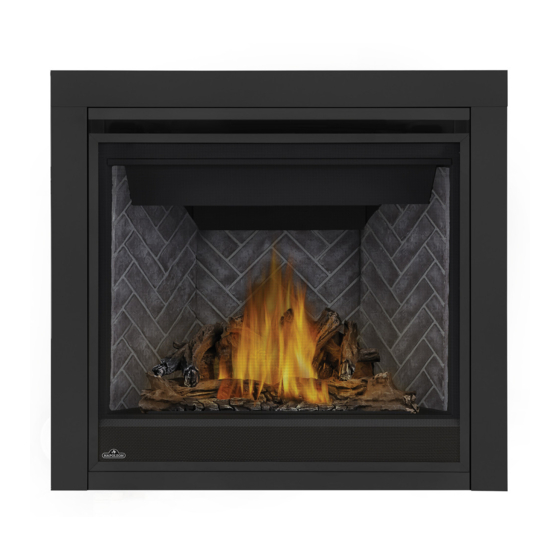
Ascent™ X 36
Product Name / Code
(MUST use title from Price Book)
ADD ____ ILLUSTRATED
ADD PRODUCT IMAGE
FOR INDOOR USE ONLY
NUMBER LABEL HERE
PLACE BARCODE LABEL ON THE
IF SEPARATE MANUALS, ADD "PLACE
OWNER'S MANUAL
ENGLISH
FRENCH PG. 75
W415-2354 / B / 12.09.20
Advertisement
Chapters
Table of Contents
Troubleshooting

Related Manuals for Napoleon Ascent X 36


Summary of Contents for Napoleon Ascent X 36
- Page 1 OWNER’S MANUAL BARCODE LABEL ON THE OWNER’S MANUAL” LOGO Wolf Steel Ltd., 24 Napoleon Rd., Barrie, ON, L4M 0G8 Canada / 103 Miller Drive, Crittenden, Kentucky, USA, 41030 Phone 1 (866) 820-8686 • www.napoleon.com • hearth@napoleon.com $10.00 W415-2354 / B / 12.09.20...
- Page 2 safety information WARNING DANGER • This appliance is hot when operated and can cause severe burns if contacted. • Any changes or alterations to this appliance or its controls can be dangerous and is prohibited. HOT GLASS WILL CAUSE • Do not operate appliance before reading and BURNS.
- Page 3 patterns. RAAK HET GLAS NIET AAN TOT HET IS AFGEKOELD. DUTCH safety information LAAT KINDEREN NOOIT HET GLAS AANRAKEN. WARNING Dit apparaat is voorzien van een barrière die is ontworpen om het risico van brandwonden door het hete kijkglas te beperken. Deze barrière moet worden geïnstalleerd ter bescherming van kinderen •...
-
Page 4: Table Of Contents
table of contents general information finish framing rates and efficiencies minimum framing dimensions installation overview 10.0 finishing rating plate information 10.1 safety barrier / door removal and mobile home installation installation dimensions 10.2 front hood installation venting requirements 10.3 non-combustible facing material typical vent installation 10.4 minimum mantel clearances... -
Page 5: General Information
standard checklist Installer: please fill out appliance checklist in the Owner's manual. 1.0 general information When the appliance is installed at elevations above 4,500ft (1372m), and in the absence of specific recommendations from the local authority having jurisdiction, the certified high altitude input rating shall be reduced at the rate of 4% for each additional 1,000ft (305m). -
Page 6: Installation Overview
standard checklist installation overview Recommended installation steps: 1. Determine venting requirements before deciding the final location of the appliance. 2. Install rough framing (see “rough framing” section). 3. Place the appliance in its final position. 4. Install appliance venting (see “venting installation” section). 5. - Page 7 general information WARNING • Always light the pilot whether for the first time or if the gas supply has run out, with the glass door opened or removed. • Provide adequate clearance for servicing and operating the appliance. • Provide adequate ventilation. •...
-
Page 8: Rating Plate Information
Recessed depth X” Profondeur d’encastré une face X” L’appareil doit être ventilé à l’aide de l’ensemble d’évacuation propre à Napoleon. Référez au *** Mantel X” from appliance opening *** Tablette X” de l’ouverture de l’appareil manuel d’installation pour les spécifications d’évacuation. Il est nécessaire de bien réinstaller et *** Maximum horizontal extension: *** L’extension horizontale maximale: X”. -
Page 9: Dimensions
general information dimensions W415-2354 / B / 12.09.20... -
Page 10: Venting Requirements
2.0 venting requirements venting requirements WARNING • Risk of fi re. Maintain specifi ed air space clearances to vent pipe and appliance. • The vent system must be supported every 3’(0.9m) for both vertical and horizontal runs. Use support ring assembly W010- 0067 or equivalent non-combustible strapping to maintain the minimum clearance to combustibles for both vertical and horizontal runs. -
Page 11: Typical Vent Installation
horizontally or three vertically (excluding the appliance and the air terminal connections) when using fl exible venting. Horizontal runs may have a 0” rise per foot or 0mm rise per meter however for optimum performance it is recommended that all horizontal runs have a minimum 1/4” rise per foot or 21mm rise per meter using fl exible venting. For safe and proper venting requirements operation of the appliance, follow the venting instructions exactly. - Page 12 venting requirements 16" (40.6cm) minimum 40 ft (12m) Maximum 3 ft (1m) minimum 20" (50.8cm) Max. 24" (61cm) 24" minimum plus rise * (61cm) REAR VENT * See "venting" section W415-2354 / B / 12.09.20...
-
Page 13: Special Vent Installations
venting requirements special vent installations 2.2.1 periscope termination Use the periscope kit to locate the air termination above grade. The periscope must be installed so that when fi nal grading is completed, the bottom air slot is located a minimum 12” (305mm) above grade. The maximum allowable vent length (including both rise and run) is 10’... -
Page 14: Minimum Air Terminal Location Clearances
venting requirements minimum air terminal location clearances Covered balcony applications ††* = 3 feet ≤ 15 feet = 2 x ACTUAL (0.9m) (4.6m) note: INSTALLATIONS Wall terminals are for illustration purposes only. Size and shapes may vary. CANADA U.S.A. 12” (30.5cm) 12”... -
Page 15: Venting Application Flow Chart
venting requirements venting application flow chart TOP EXIT Horizontal Termination Vertical Termination Vertical rise is equal Vertical rise is equal Vertical rise is less Vertical rise is less to or greater than to or greater than than horizontal run than horizontal run the horizontal run the horizontal run Horizontal run +... -
Page 16: Definitions
venting requirements definitions For the following symbols used in the venting calculations and examples are: > - greater than > - equal to or greater than < - less than < - equal to or less than - total of both horizontal vent lengths (Hr) and offsets (Ho) in feet - combined horizontal vent lengths in feet - offset factor: .03 (total degrees of offset - 90°*) in feet - combined vertical vent lengths in feet... -
Page 17: Top Exit Horizontal Termination
venting requirements top exit horizontal termination ) < (V See graph to determine the required vertical Simple venting confi guration (only one 90° elbow) rise V for the required horizontal run H 40 (12.2) 40 (12.2) 39 (11.9) 39 (11.9) REQUIRED 30 (9.1) REQUIRED... - Page 18 venting requirements ) > (V Simple venting configuration See graph to determine the required vertical rise V for the required horizontal run H (only one 90° elbow) 150 (381) 147 (373) REQUIRED VERTICAL 100 (254) RISE IN INCHES (CENTIMETERS) V 57 (145) 50 (127) 8 (20.3)
-
Page 19: Rear Exit Horizontal Termination
venting requirements rear exit horizontal termination ) < (V Simple venting configuration See graph to determine the required vertical rise V for the required (only two 90° elbows) horizontal run H 40 (12.2) 35.3 (10.7) REQUIRED 30 (9.1) VERTICAL RISE IN 20 (6.1) FEET (METERS) V... - Page 20 venting requirements ) > (V Simple venting configuration See graph to determine the required vertical rise V for the (only two 90° elbows) required horizontal run H 12.5 (3.8) 12.25 (3.7) REQUIRED VERTICAL RISE IN 8.3 (2.54) FEET (METERS)V (1.68) 4.2 (1.3) (0.3) 12.5...
-
Page 21: Top And Rear Exit Vertical Termination
venting requirements top and rear exit vertical termination ) < (V See graph to determine the required vertical rise V for the Simple venting configurations. required horizontal run H 40 (12.2) 30 (9.1) REQUIRED VERTICAL RISE IN FEET 20 (6.1) (METERS)V 10 (3.1) 3 (0.9) - Page 22 venting requirements ) > (V See graph to determine the required vertical rise V for the Simple venting configurations. required horizontal run H 20 (6.1) 19 (5.8) REQUIRED VERTICAL 10 (3.1) RISE IN FEET 3 (0.9) (METERS)V (1.5) (3.1) (4.6) (6.1) (7.6) (9.1)
-
Page 23: Rear Exit
venting requirements Example: = 1.5 FT (0.5m) = 5 FT (1.5m) = 1.5FT (0.5m)+ 5FT (1.5m) = 6.5 FT (2m) = 1 FT (0.3m) = 1 FT (0.3m) = 10.75 FT (3.3m) = 1FT (0.3m) + 1FT (0.3m) + 10.75FT (3.3m) = 12.75FT (3.9m) = .03 (three 90°... -
Page 24: Rear Exit Shield (For Rear Vent Only)
venting requirements 2.11 rear exit shield (for rear vent only) Remove the safety barrier assembly and door from the appliance, refer to the “safety barrier & door removal / installation” section of the manual for detailed instructions. Loosen the two screws, that secure the exhaust plate, and slide the shield in place by sliding its slotted openings behind the screwheads, tighten the two previously loosened screws. -
Page 25: Top Exit
venting requirements 2.12 top exit WARNING • Failure to install the cover plate and gasket will cause the appliance to function improperly and can cause injury or property damage. This appliance has been factory shipped as a rear vent. Remove the safety barrier and glass door (see "safety barrier & door removal/installation" section). FIG. -
Page 26: Rough Framing
3.0 rough framing rough framing note: When using optional fi nishing accessories, the framing dimensions and fi nishing materials may differ from what is outlined in the section below; refer to the leafl et instructions supplied in the accessory kit for specifi c framing and fi nishing specifi cations. -
Page 27: Minimum Framing Dimensions
rough framing minimum framing dimensions 33 7/8” SIDE WALL (86cm) 2” (51mm) 35 1/2” (90.2cm) Do not put objects in front of the appliance (minimum distance of 4 feet) 16” (40.6cm) HORIZONTAL VENT SECTIONS: A minimum of 1" (25mm) at the bottom and sides, and 3" (76.2mm) at the top of the vent pipe on all horizontal runs to combustibles is required. -
Page 28: Minimum Enclosure Clearances
rough framing minimum enclosure clearances TOP VENT PLAFOND CEILING ENCLOSURE TOP EXIT ENCLOSURE The appliance requires a minimum enclosure height of 50 1/2" (128.3cm). For temperature requirements, the enclosure space around and above the appliance must be left unobstructed. NOTE: The vent shield is telescopic and must be adjusted to shield the full depth of the combustible wall penetration. - Page 29 rough framing MINIMUM REAR VENT CLEARANCES For rear vent termination not exceeding 10" (254mm) of horizontal vent run. Ceiling Plafo Enclosure 24" (61cm) REAR EXIT ENCLOSURE The appliance requires a minimum enclosure height of 44" (111.8cm). For temperature requirements, the enclosure space around and above the appliance must be left unobstructed.
- Page 30 rough framing MAXIMUM REAR VENT CLEARANCES (EXAMPLE 1: INTERIOR NICHE / BUMPOUT / ALCOVE) 24" (61cm) REAR EXIT ENCLOSURE The appliance requires a minimum enclosure height of 44" (111.8cm). For temperature requirements, the enclosure space around and above the appliance must be left unobstructed. NOTE: The vent shield is telescopic and must be adjusted to shield the full depth of the combustible wall penetration.
- Page 31 rough framing MAXIMUM REAR VENT CLEARANCES (EXAMPLE 2: EXTERIOR ALCOVE / DOGHOUSE) 24" (61cm) REAR EXIT ENCLOSURE The appliance requires a minimum enclosure height of 44" (111.8cm). For temperature requirements, the enclosure space around and above the appliance must be left unobstructed. NOTE: The vent shield is telescopic and must be adjusted to shield the full depth of the combustible wall penetration.
- Page 32 rough framing note: For heavier finishing materials such as marble, we recommend adding extra support to the frame. Ensure there is adequate floor support for the appliance and finishing material. Before framing your appliance, determine vent requirements before deciding the final location of the appliance. After rough framing, place the appliance in its final position.
-
Page 33: Venting Installation
venting installation 4.0 venting installation WARNING • Ensure to unpack all loose materials from inside the fi rebox prior to connecting the gas and electrical supply • If your appliance is supplied with a remote, ensure the remote receiver is in the “OFF” position prior to connecting the gas and electrical supply to the appliance. -
Page 34: Horizontal Installation
venting installation horizontal installation WARNING • The fi restop assembly must be installed with the vent shield to the top. • Terminals must not be recessed into a wall or siding more than the depth of the return fl ange of the mounting plate. -
Page 35: Vertical Installation
venting installation vertical installation This application occurs when venting through a roof. Installation kits for various roof pitches are available from your authorized dealer / distributor. See the “accessories” section to order specifi c kits required. A. Determine the air terminal location, cut and frame a square opening, as illustrated, in the ceiling and the roof to provide the minimum 1"... -
Page 36: Using Either Flexible Or Rigid Vent Components
venting installation using either flexible or rigid vent components WARNING • Do not allow the inner fl ex pipe to bunch up on horizontal or vertical runs and elbows. Keep it pulled tight. • Spacers are attached to the inner fl ex pipe at predetermined intervals to maintain an even air gap to the outer fl ex pipe. -
Page 37: Vertical Air Terminal Installation
venting installation 4.3.2 vertical air terminal installation WARNING • Maintain a minimum 2” (51mm) space between the air inlet base and the storm collar. note: Fastening hardware provided with appropriate roof terminal and liner kits. Fasten the roof support to the roof using 6 screws. The roof support is optional. -
Page 38: Horizontal Air Terminal Installation
venting installation 4.3.4 horizontal air terminal installation Move the appliance into position. Measure #10x2" the vent length required between terminal and SCREWS appliance taking into account the additional CAULKING length needed for the fi nished wall surface and any 2” (50.8mm) overlaps between venting INNER components. -
Page 39: Vertical Air Terminal Installation
venting installation 4.3.5 vertical air terminal installation WARNING • Maintain a minimum 2” (51mm) space between the air inlet base and the storm collar. note: Fastening hardware provided with appropriate roof terminal and liner kits. Before attaching elbows to the collars on the back of the appliance, 1 1/2” (38.1mm) will need to be trimmed off the 4”... -
Page 40: Vertical Through Existing Chimney
venting installation vertical through existing chimney WARNING • Risk of fi re. • Co-axial to co-linear venting confi gurations must only be used in a non-combustible chimney or enclosure. Installation in a combustible enclosure could result in a fi re. This appliance is designed to be attached to a 3”... -
Page 41: Restricting Vertical Vents
venting installation 4.4.1 restricting vertical vents WARNING • Turn off gas and electrical supply before servicing the appliance. • Appliance may be hot, do not service until appliance is cool. • For safe and proper operation of the appliance, follow the venting instruction exactly. •... -
Page 42: Electrical Information
venting installation 5.0 electrical information hard wiring connection It is necessary to hard wire this appliance. This appliance must be electrically connected and grounded in accordance with local codes. In the absence of local codes, use the current CSA C22.1 Canadian Electrical Code in Canada or the ANSI/NFPA 70-1996 National Electrical Code in the United States. -
Page 43: Battery Back-Up Installation
electrical information battery back-up installation note: In the event of a power failure, your appliance can be operated using the battery back-up supplied. Remove the safety barrier by lifting it up and off of the four shoulder screws. Locate your battery holder, this would have been supplied in the manual baggie. Locate the red and black wires from the control module to connect to the battery holder, as shown below. -
Page 44: Gas Installation
6.0 gas installation gas installation WARNING • Risk of fi re, explosion, or asphyxiation. Ensure there are no ignition sources such as sparks or open fl ames. • Support gas control when attaching gas supply pipe to prevent damaging gas line. •... -
Page 45: Operation (Electronic)
7.0 operation (electronic) operation WARNING • If you do not follow these instructions exactly, a fi re or explosion may result causing property damage, personal injury, or loss of life. • If applicable, always light the pilot whether for the fi rst time or if the gas supply has run out with the glass door opened or removed. -
Page 46: Pilot On Demand
In order to start your pilot, turning the main burner on with the switch, remote or thermostat and then turning it off will reactivate the continuous pilot mode and reset the seven day timer. For further information, refer to www.napoleon.com/pilotondemand. 31.2A... -
Page 47: Operation (Millivolt)
operation (electronic) 8.0 operation (millivolt) WARNING • If you do not follow these instructions exactly, a fi re or explosion may result causing property damage, personal injury, or loss of life. • If applicable, always light the pilot whether for the fi rst time or if the gas supply has run out with the glass door opened or removed. -
Page 48: Finish Framing
9.0 finish framing finish framing minimum framing dimensions WARNING • Risk of fire! • Maintain all specified air space clearances to combustibles. Failure to comply with these instructions may cause a fire or cause the appliance to overheat. • Ensure all clearances (i.e. back, side, top, vent, mantel, front, etc.) are clearly maintained. 35"... -
Page 49: Finishing
finishing 10.0 finishing WARNING • Risk of fire! • Never obstruct the front opening of the appliance. • The front of the appliance must be finished with any non-combustible materials such as brick, marble, granite, etc., provided that these materials do not go below the specified dimension, as illustrated. •... -
Page 50: Front Hood Installation
finishing 10.2 front hood installation note: This hood must be installed, if it has not already been factory installed. Safety door and screen must be removed. Remove the securing screws from the top of the firebox, as shown. Install the front hood, ensure it is angled downward when installed. Reinstall the previously removed securing screws. -
Page 51: Non-Combustible Facing Material
finishing 10.3 non-combustible facing material WARNING Non-combustible facing material must not project more than 4” (101.6mm) from the face of the door (all four sides). If greater projections are desired, increase the clearance to the sides, bottom and top by 2” (50.8mm) for every additional 1”... -
Page 52: Minimum Mantel Clearances
finishing 10.4 minimum mantel clearances WARNING • Risk of fi re. Maintain all specifi ed air space clearances to combustibles. Failure to comply with these instructions may cause a fi re or cause the appliance to overheat. Ensure all clearances (i.e. back, side, top, vent, mantel, front, etc.) are clearly maintained. -
Page 53: Recessed Installation
finishing 10.5 recessed installation WARNING • Installing a television or other electronics above the appliance may cause discolouration, melting, or damage to the electronics. Use clearances as guidelines and refer to your TV manufacturer’s instructions for further information Image note: Recesses or alcoves above the appliance must be made with non-combustible material and regular minimum clearances, as defi ned for combustible materials, must still be applied. -
Page 54: Log Placement
The logs are fragile and should be handled with care. If applicable, insert the following statement: PHAZER™ logs and glowing embers, exclusive to Napoleon, provide a unique and realistic glowing effect that “PHAZER™ logs [and glowing embers], exclusive to Napoleon/Continental, provide a unique and realistic is different in every installation. - Page 55 Stud (Log #3) Stud (Log #3) Studs (Log #4) Studs (Log #4) finishing Stud (Log #2) Stud (Log #2) Stud (Log #2) Stud (Log #2) Notch Notch Stud (Log #3) Stud (Log #3) Studs (Log #4) Studs (Log #4) Notch Notch Stud (Log #3) Stud (Log #3)
-
Page 56: Glowing Embers
NOTE: ENSURE NOMENCLATURE IS NOTE: ENSURE NOMENCLATURE IS CONSISTENT THROUGHOUT. CONSISTENT THROUGHOUT. finishing IF SPACE IS LEFT OVER, USE THIS BOX TO IF SPACE IS LEFT OVER, USE THIS BOX TO SHOW CORRECT FINAL LOG PLACEMENT SHOW CORRECT FINAL LOG WITH LINE DRAWINGS. -
Page 57: Optional Blower Installation
NOTE: fOr mOrE dETailEd iNsTrucTiONs rEfEr TO yOur iNsTallaTiON maNual. NOTE: fOr mOrE dETailEd iNsTrucTiONs rEfEr TO yOur iNsTallaTiON maNual. W415-1479 / A / 05.09.16 W415-1479 / A / 05.09.16 Wolf Steel Ltd., 24 Napoleon Rd., Barrie, ON L4M 0G8 Canada • (705)721-1212 • fax (705)720-9081 • www.napoleonfireplaces.com Wolf Steel Ltd., 24 Napoleon Rd., Barrie, ON L4M 0G8 Canada... -
Page 58: Adjustments
12.0 adjustments adjustment 12.1 pilot burner adjustment Adjust the pilot screw to provide properly sized PILOT ELECTRODE flame. Turn in a clockwise direction to reduce the BURNER ELECTRONIC 3/8” - 1/2” ILLUSTRATED gas flow. (9.5mm - 12.7mm) Adjust the pilot screw to provide properly sized fl ame. Turn in a clockwise direction to reduce the gas fl ow. FLAME SENSOR Check Pressure Readings:... -
Page 59: Flame Characteristics
(12.7mm - 9.5mm) of (9.5 thermocouple adjustment 12.3 flame characteristics SIT ELECTRONIC IGNITION It’s important to periodically perform a visual check of 3/8” - 1/2” the pilot and burner flames. Compare them to the ADD IMAGE (9.5mm - 12.7mm) illustration provided. If any flames appear abnormal, call a service person. -
Page 60: Maintenance
13.0 maintenance maintenance WARNING • Turn off the gas and electrical power before servicing the appliance. • Appliance may be hot. Do not service until appliance has cooled. • Do not use abrasive cleaners on glass. • Do not paint the pilot assembly. This appliance and its venting system should be inspected before use and at least annually by a qualifi ed service person. -
Page 61: Annual Maintenance
maintenance 13.1 annual maintenance WARNING • Annual maintenance should be performed by a qualifi ed service technician • The fi rebox becomes very hot during operation. Let the appliance cool completely or wear heat resistant gloves before conducting service. • Never vacuum hot embers. -
Page 62: Door Glass Replacement
maintenance 13.2 door glass replacement WARNING • Do not use substitute materials. • Glass may be hot. Do not touch glass until cooled. • Care must be taken when removing and disposing of any broken door glass or damaged components. Be sure to vacuum up any broken glass from inside appliance before operation. -
Page 63: Replacement Parts
replacement parts 14.0 replacement parts WARNING • Failure to position the parts in accordance with this manual or failure to use only parts specifi cally approved with this appliance may result in property damage or personal injury. • **This is a fast acting thermocouple. It is an integral safety component. Replace only with a fast acting supplied by Wolf Steel Ltd. -
Page 64: Overview
replacement parts W415-2354 / B / 12.09.20... -
Page 65: Millivolt Valve Train Assembly
replacement parts W415-2354 / B / 12.09.20... -
Page 66: Electronic Valve Train Assembly
replacement parts W415-2354 / B / 12.09.20... -
Page 67: Troubleshooting (Electronic)
15.0 troubleshooting (electronic) troubleshooting (electronic) WARNING • Always light the pilot whether for the fi rst time or if the gas supply has run out, with the glass door open or removed. • Turn off gas and electrical power before servicing the appliance. •... - Page 68 Check that venting is installed correctly. appliances). Room is in negative pressure; increase fresh air supply. troubleshooting (electronic) symptom problem test solution Pilot will not light. Makes Wiring: short, loose, or damaged Verify the thermocouple/sensor is clean and the wiring is undamaged. Verify the interrupter block is not damaged or too tight.
- Page 69 Wire connector pins are bent. Straighten pins. Valve wiring is damaged. Replace valve. troubleshooting (electronic) symptom problem test solution Lights or blower Control module switch in Verify ON/OFF switch is in the “I” position which denotes on. won’t function (if wrong position.
-
Page 70: Troubleshooting (Millivolt)
16.0 troubleshooting (millivolt) troubleshooting (millivolt) WARNING • Always light the pilot whether for the fi rst time or if the gas supply has run out, with the glass door open or removed. • Turn off gas and electrical power before servicing the appliance. •... - Page 71 troubleshooting (millivolt) symptom problem test solution Pilot will not light. No spark at pilot burner. Check if pilot can be lit by a match. Check that the wire is connected to the push button ignitor. Check if the push button ignitor needs tightening. PILOT Replace the wire if the wire insulation is broken or frayed.
-
Page 72: Warranty
Napoleon neither assumes, nor authorizes any third party to assume, on its behalf, any other liabilities with respect to the sale of this product. Napoleon will not be responsible for: over- fi ring, downdrafts, spillage caused by environmental conditions such as rooftops, buildings, nearby trees, hills, mountains, inadequate vents or ventilation, excessive venting confi gurations, insuffi cient makeup air, or negative air pressures which may or may not be caused by mechanical systems such as exhaust fans, furnaces, clothes dryers, etc. - Page 73 notes 29.1 W415-2354 / B / 12.09.20...
- Page 74 NAPOLEON CELEBRATING OVER 40 YEARS OF HOME COMFORT PRODUCTS 7200, Route Transcanadienne, Montréal, Québec H4T 1A3 24 Napoleon Road, Barrie, Ontario, Canada L4M 0G8 214 Bayview Drive, Barrie, Ontario, Canada L4N 4Y8 103 Miller Drive, Crittenden, Kentucky, USA 41030 De Riemsdijk 22, 4004 LC Tiel, The Netherlands Phone: 1-866-820-8686 napoleon.com...
- Page 75 LE MANUEL DU PROPRIÉTAIRE LOGO BARCODE LABEL ON THE OWNER’S MANUAL” Wolf Steel Ltd., 24 Napoleon Rd., Barrie, ON, L4M 0G8 Canada / 103 Miller Drive, Crittenden, Kentucky, USA, 41030 Téléphone 1(866)820-8686 • www.napoleon.com • hearth@napoleon.com W415-2354 / B / 12.09.20...
- Page 76 NEVER ALLOW CHILDREN TO TOUCH GLASS. A barrier designed to reduce the risk of burns from the hot consignes de sécurité viewing glass is provided with this appliance and must be installed for the protection of children and other at-risk AVERTISSEMENT individuals.
- Page 77 continue de s’éteindre, faire réparer. Garder propres le brûleur et le compartiment de contrôle. • Cet appareil ne devra être modifi é en aucun cas. • Ne laissez pas les ventilateurs souffl er directement sur l’appareil. Empêchez les courants d’air de modifi er consignes de sécurité...
- Page 78 table des matières information électrique information générales branchement par câble taux et efficacités vue d'ensemble d'installation schéma de câblage électronique information à propos de la plaque installation du sauvegarde de pile d’homologation branchement de gaz installation dans une maison mobile opération (électronique) dimensions veilleuse sur demand...
-
Page 79: Taux Et Efficacités
liste de vérification Installer: veuillez remplir la liste de contrôle de l'appareil dans le manuel du propriétaire. 1.0 information générales Lorsque l’appareil est installé à des élévations dépassant 4,500 pieds (1372m), et en l’absence de recommandations spécifiques de l’autorité compétente locale, l’indice certifié du débit à haute altitude devra être réduit au taux de 4% pour chaque 1,000 pieds (305m) supplémentaires. -
Page 80: Information Générales
information générales vue d'ensemble d'installation Étapes d'installation recommandées: 1. Determinez les exigences d'évacuation avant de determinez le position finale de l'appareil. 2. Installez l'encadrement approximatif (voir la section « encadrement approximatif »). 3. Placez l'appareil dans le position finale. 4. Installez l'évacuation de l'appareil (voir la section « installation d'évacuation »). 5. - Page 81 information générales AVERTISSEMENT • Allumez toujours la veilleuse, que ce soit pour la première fois ou lorsque l’approvisionnement en gaz est épuisé, avec la porte vitrée ouverte ou retirée. • Prévoyez un accès suffisant pour entretenir et opérer l’appareil. • Assurez-vous d’une quantité...
-
Page 82: Information À Propos De La Plaque
Recessed depth X” Profondeur d’encastré une face X” L’appareil doit être ventilé à l’aide de l’ensemble d’évacuation propre à Napoleon. Référez au *** Mantel X” from appliance opening *** Tablette X” de l’ouverture de l’appareil manuel d’installation pour les spécifications d’évacuation. Il est nécessaire de bien réinstaller et *** Maximum horizontal extension: *** L’extension horizontale maximale: X”. - Page 83 information générales dimensions W415-2354 / B / 12.09.20...
-
Page 84: Exigences D'évacuation
2.0 exigences d'évacuation exigences d'évacuation AVERTISSEMENT • Risque d’incendie. Conservez les dégagements nécessaires au conduit d’évent et à l’appareil. • Les courses horizontales et verticales du système doivent être supportées à tous les 3 pi (0,9m). Utilisez l’ensemble de support mural Wolf Steel W010-0067 ou des attaches incombustibles équivalents afi n de maintenir le dégagement aux matériaux combustibles pour les courses verticales et horizontales. -
Page 85: Installations Typiques D'évents
Pour une performance optimale de l’appareil et une apparence optimale des fl ammes, gardez la longueur des évents et le nombre de coudes au minimum. exigences d'évacuation La prise d’air de la terminaison extérieure doit demeurer dégagée en tout temps. Vérifi ez la prise d’air de la terminaison au moins une fois l’an pour vous assurer qu’elle n’est pas obstruée ni endommagée. - Page 86 exigences d'évacuation 16" (40,6cm) minimum 40 FT (12m) Maximum 3 ft (1m) minimum 20" (50,8cm) 24" 24" (61cm) (61cm) minimum plus la pente* ÉVACUATION SUR L’ARRIÈRE * Voir la section « ÉVACUATION » W415-2354 / B / 12.09.20...
-
Page 87: Installations Particulières D'évents
exigences d'évacuation installations particulières d'évents 2.2.1 ensemble périscopique Utilisez l’ensemble périscopique afi n de positionner la terminaison au-dessus du niveau du sol. L’ensemble périscopique doit être installé de façon à ce que la fente d’air du bas soit située à un minimum de 12 pouces (305mm) au-dessus du niveau du sol. -
Page 88: Emplacements Et Dégagements Minimaux De La Terminaison
exigences d'évacuation emplacements et dégagements minimaux de la terminaison Applications pour balcon couvert ††* = 3 feet ≤ 15 feet = 2 x ACTUAL (0.9m) (4.6m) note: INSTALLATIONS Les terminaux du mur sont à des fi ns d’illustration seulement. La taille et les formes peuvent varier. CANADA É.-U. -
Page 89: Charte D'application Des Évacuations
exigences d'évacuation charte d'application des évacuations ÉVACUATION SUR LE DESSUS Terminaison horizontale Terminaison verticale La course verticale La course verticale est La course verticale La course verticale est est plus petite que la est plus petite que la plus grande ou égale à plus grande ou égale à... -
Page 90: Valeurs Du Coude En Longueurs D'évent
exigences d'évacuation valeurs du coude en longueurs d'évent PIEDS POUCES MILLIMÈTRES 1° 0,03 12,7 15° 0,45 152,4 30° 11,0 279,4 45° 1,35 16,0 406,4 90°* 32,0 812,8 * La première déviation de 90° a une valeur zéro et est illustrée dans la formule comme - 90° 15.1A évacuation sur le dessus terminaison horizontale ) <... - Page 91 exigences d'évacuation ) > (V Configuration d'évacuation simple Consultez le graphique pour déterminer la course verticale nécessaire V (un coude de 90° seulement) par rapport à la course horizontale requise H 150 (381) 147 (373) COURSE VERTICALE 100 (254) REQUISE EN POUCES (CENTIMÈTRES)V 57 (145)
-
Page 92: Évacuation Sur L'arriére Terminaison Horizontale
exigences d'évacuation évacuation sur l'arriére terminaison horizontale ) < (V Configuration d'évacuation simple Consultez le graphique pour déterminer la course verticale nécessaire (deux coudes de 90° seulement) par rapport à la course horizontale requise H 40 (12,2) 38,3 (11,7) COURSE 30 (9,1) VERTICALE REQUISE... - Page 93 exigences d'évacuation ) > (V Configuration d'évacuation simple Consultez le graphique pour déterminer la course verticale (deux coudes de 90° seulement) nécessaire V par rapport à la course horizontale requise H 12,5 (3,8) 12,25 (3,7) COURSE VERTICALE 8,3 (2,54) REQUISE EN PIEDS (MÈTRES) V (1,68)
-
Page 94: Évacuation Sur L'arriére Et Au Dessus
exigences d'évacuation évacuation sur l'arriére et au dessus terminaison verticale ) < (V Consultez le graphique pour déterminer la course verticale Configurations d'évacuation simples. nécessaire V par rapport à la course horizontale requise H 40 (12,2) 30 (9,1) COURSE VERTICALE 20 (6,1) REQUISE EN PIEDS... - Page 95 exigences d'évacuation ) > (V Configurations d'évacuation simples. Consultez le graphique pour déterminer la course verticale nécessaire V par rapport à la course horizontale requise H 20 (6,1) 19 (5,8) COURSE VERTICALE REQUISE EN 10 (3,1) PIEDS (MÈTRES) V 3 (0,9) (1,5) (3,1) (4,6)
-
Page 96: Évacuation À L'arrière
exigences d'évacuation 2.10 évacuation à l'arrière AVERTISSEMENT • Il est essentiel que le couvercle d'évacuation soit installé. si non, l'appareil ne fonctionnera pas correcte- ment et pourrait causer des blessures ou des dommages matériels. Fig. 1 Enlevez l'écran de protection et vitre de la porte, référer de la section, «... -
Page 97: Déflecteur Du Ventilation Arrière (Pour L'application De Ventilation Arrière)
exigences d'évacuation 2.11 déflecteur du ventilation arrière (pour l'application de ventilation arrière) Retirez l'assemblage de l'écran de protection et la porte de l'appareil, consultez la section « installation et enlevement de l'écran de protection et la porte » du manuel pour obtenir des instructions détaillées. Desserrez les deux vis servant à... -
Page 98: Évacuation Sur Le Dessus
exigences d'évacuation 2.12 évacuation sur le dessus AVERTISSEMENT • Il est essentiel que le couvercle d'évacuation soit installé, si non, l'appareil ne fonctionnera pas correcte- ment et pourrait causer des blessures ou des dommages matériels. Cette appareil a été expédié avec une évacuation à l'arrière. Enlevez l'écran de protection et vitre de la porte (voir la section «... -
Page 99: Encadrement Approximatif
encadrement approximatif 3.0 encadrement approximatif note: Lorsque vous installez les accessoires de fi nition optionelles, les dimensions de l’ossature et les matériaux de fi nition peuvent différer de ce qui est décrit dans ces instructions ci-dessous, voir les instructions fournies dans le trousse de l’accessoire pour les spécifi cations détaillées. -
Page 100: Dégagements Minimaux De L'ossature
encadrement approximatif dégagements minimaux de l'ossature 33 7/8” mur de côté (86cm) 2” (51mm) 35 1/2” (90.2cm) Ne placez pas d’objets devant l’appareil Do not put objects in front of the appliance (distance minimale de 4 pieds) (minimum distance of 4 feet)* 16”... -
Page 101: Dégagements Minimaux De L'enceinte
encadrement approximatif dégagements minimaux de l'enceinte ÉVACUATION SUR LE DESSUS PLAFOND ENCEINTE ENCEINTE AVEC ÉVACUATION SUR LE DESSUS L'enceinte de l'appareil doit avoir une hauteur minimale de 50 1/2" (128,3cm). Afin de respecter les contraintes de température, l’espace à l’intérieur de l’enceinte, autour de l'appareil et au-dessus, doit demeurer sans obstruction. NOTE: L'écran de protection est télescopique et doivent être ajusté... - Page 102 encadrement approximatif DÉGAGEMENTS MINIMAUX DE L'ÉVACUATION À L'ARRIÈRE Pour la ventilation arrière ne dépassement pas 10" (254mm) de section horizontale de ventilation. Plafond Enceinte 24" (61cm) ENCEINTE AVEC ÉVACUATION À L'ARRIÈRE L'enceinte de l'appareil doit avoir une hauteur minimale de 44" (111,8cm). Afin de respecter les contraintes de température, l’espace à...
- Page 103 encadrement approximatif DÉGAGEMENTS MAXIMAUX DE ÉVACUATION À L'ARRIÈRE (EXEMPLE 1: NICHE / BUMPOUT / ALCÔVE INTÉRIEUR) 24" (61cm) ENCEINTE AVEC ÉVACUATION À L'ARRIÈRE L'enceinte de l'appareil doit avoir une hauteur minimale de 44" (111,8cm). Afin de respecter les contraintes de température, l’espace à l’intérieur de l’enceinte, autour de l'appareil et au-dessus, doit demeurer sans obstruction.
- Page 104 encadrement approximatif DÉGAGEMENTS MAXIMAUX DE ÉVACUATION À L'ARRIÈRE (EXEMPLE 2: ALCÔVE / NICHE EXTÉRIEUR) 24" (61cm) ENCEINTE AVEC ÉVACUATION À L'ARRIÈRE L'enceinte de l'appareil doit avoir une hauteur minimale de 44" (111,8cm). Afin de respecter les contraintes de température, l’espace à l’intérieur de l’enceinte, autour de l'appareil et au-dessus, doit demeurer sans obstruction.
- Page 105 encadrement approximatif note: Pour les matériaux de finition plus lourds comme du marbre, nous vous recommandons d’ajouter un support additionnel à l’ossature. Assurez-vous que le support de plancher est adéquat pour l’appareil et le matériau de fintion. Avant d’encadrer votre appareil, déterminez les exigences de ventilation avant de décider de l’emplacement finale de l’appareil.
-
Page 106: Installation D'évacuation
installation d'évacuation 4.0 installation d'évacuation AVERTISSEMENT • Avant d’effectuer les branchements pour l’alimentation en gaz et électronique, assurez-vous de retirer toute composante non fi xée à l’intérieur de la chambre de combustion. • Si votre appareil comprend un système de télécommande, assurez-vous que le récepteur est à la position «... -
Page 107: Installation Horizontale
installation d'évacuation installation horizontale AVERTISSEMENT • L’espaceur coupe-feu doit être installé avec l’écran protecteur orienté vers le haut. • La terminaison ne doit pas être enchâssée dans le mur ou le revêtement extérieur plus que l’épaisseur de la bride de la plaque de montage. •... -
Page 108: Installation Verticale
installation d'évacuation installation verticale Cette confi guration s’applique lorsque l’évacuation se fait à travers un toit. Des ensembles d’installation pour les différentes pentes de toit sont disponibles chez votre détaillant autorisé. Voir la section « accessoires » dans le manuel du propriétairepour commander l’ensemble spécifi que dont vous avez besoin. -
Page 109: Flexibles Ou Rigides
installation d'évacuation utilisation de composants d’évacuation flexibles ou rigides AVERTISSEMENT • Ne laissez pas la gaine fl exible se tasser contre les courses horizontales ou verticales et les coudes. Gardez-la tendue. • Des espaceurs sont fi xés à la gaine fl exible à intervalles prédéterminés afi n de garder un espace vide avec le conduit extérieur. -
Page 110: Installation De La Terminaison Verticale
installation d'évacuation 4.3.1 installation de la terminaison verticale AVERTISSEMENT • Conservez un espace minimale de 2 po (51mm) entre la base de la prise d’air et le collet de solin. Matériel de fi xation fourni avec les ensembles de terminal pour toit et raccord appropriées. Fixez le support de toit au toit à... -
Page 111: Installation De La Terminaison
installation d'évacuation 4.3.3 installation de la terminaison horizontale Mettez l’appareil en place. Mesurez la longueur #10x2" d’évent requise entre la terminaison et l’appareil en tenant compte de la longueur additionnelle CALFEUTRAGE nécessaire pour la surface du mur fi ni et tout chevauchement de 2”... -
Page 112: Installation De La Terminaison Verticale
installation d'évacuation 4.3.4 installation de la terminaison verticale AVERTISSEMENT • Conserves un espace minimal de 2” (51mm) entre la base de la prise d’air et le collet de solin. note: Avant de fi xer les coudes aux collets à l’arriére de l’appareil, enlevez 1 1/2” (38.1mm) au collet de 4” (101.6mm) Matériel de fi xation fourni avec les ensembles de terminaison pour toit et raccord appropriée. -
Page 113: Terminaison Verticale À Travers Une Cheminée Existante
installation d'évacuation terminaison verticale à travers une cheminée existante AVERTISSEMENT • Risque d’incendie • Les confi gurations d’évacuation coaxiales à colinéaires ne doivent être utilisées que dans une cheminée ou une enceinte de nature incombustible. Une installation dans une enceinte combustible peut causer un incendie. Cet appareil est conçu pour être raccordé... -
Page 114: Renstreignant Des Évents Verticaux
installation d'évacuation 4.4.1 renstreignant des évents verticaux AVERTISSEMENT • Mettez hors tension de gaz et de l'alimentation électrique avant d'intervenir sur l'appareil. • L'appareil peut être chaud, pas de service jusqu'à ce que l'appareil est refroidi. • Pour l'utilisation sure et correcte de l'appareil, suivez les instructions d'évacuation exactement. •... -
Page 115: Information Électrique
5.0 information électrique information électrique branchement par câble Vous devez effectuer un branchement par câble avec cet appareil. Cet appareil doit être raccordé électriquement et mis à la terre conformément aux codes locaux. En l'absence de codes locaux, utilisez la version courante du Code Canadienne de l'Électricité CSA C22.1 au Canada ou le National Electrical Code ANSI / NFPA 70-1996 aux États-Unis. -
Page 116: Installation Du Sauvegarde De Pile
information électrique installation du sauvegarde de pile note: En cas d'une panne de courant, votre appareil peut fonctionner utilisant le sauvegarde de pile fourni. Enlever l’écran de protection en le levant vers le haut hors des quatre vis d’épaulement. Trouver votre sauvegarde de pile, fourni aux sac du manuel. Localiser les fils rouge et noir du module de contrôle pour brancher à... -
Page 117: Branchement De Gaz
6.0 branchement de gaz branchement de gaz AVERTISSEMENT • Risque d’incendie, d’explosion, ou d’asphyxie. Assurez-vous qu’il n’y ait aucune source d’allumage comme des étincelles ou une fl amme nue. • Soutenez le contrôle du gaz lorsque vous attachez le tuyau pour éviter de plier la conduite de gaz. •... -
Page 118: Opération (Électronique)
opération 7.0 opération (électronique) AVERTISSEMENT • Si ces instructions ne sont pas suivies à la lettre, un incendie ou une explosion pourraient s’ensuivre, causant des dommages matériels, des blessures corporelles ou des pertes de vie. • Si applicable, allumez toujours la veilleuse, que ce soit pour la première fois ou lorsque l’approvisionnement en gaz est épuisé, avec la porte vitrée ouverte ou retirée. -
Page 119: Veilleuse Sur Demand
Pour démarrer la veilleuse, en allumant le brûleur principal à l’aide de l’interrupteur, de la télécommande ou du thermostat, et ensuite en l’éteignant, réactivera le mode veilleuse permanente et réinitialisera la minuterie de sept jours. Pour plus d’informations, consultez le site www.napoleon.com/pilotondemand. 31.2A W415-2354 / B / 12.09.20... -
Page 120: Opération (Millivolt)
opération (électronique) 8.0 opération (millivolt) AVERTISSEMENT • Coupez l’alimentation électrique à l’appareil et laissez-le refroidir avant d’effectuer un entretien. Seulement un • Si ces instructions ne sont pas suivies à la lettre, un incendie ou une explosion pourraient s’ensuivre, causant technicien de service qualifi é... -
Page 121: Dimensions Minimaux De L'ossature
88.9cm 9.0 encadrement fini encadrement fini dimensions minimaux de l'ossature AVERTISSEMENT • Risque d'incendie! • Conservez tous les dégagements aux matériaux combustibles spécifiées. Ne pas respecter ces instructions 16" peut causer un incendie ou une surchauffe. 40.6cm • Assurez-vous que tous les dégagements (arrière, côtés, dessus, évents, tablette, façade, etc.) sont respectés à... -
Page 122: Finitions
finitions 10.0 finitions AVERTISSEMENT • Risque d'incendie! • N'obstruez jamais l'ouverture sur le devant de l'appareil. • La finition de la façade doit être fait avec de matériau incombustible comme de la brique, du marbre du granite, etc., sous réserve que ces matériaux ne dépassent pas le dimension spécifiée, comme illustré. •... -
Page 123: Installation De L'hotte Avant
finitions 10.2 installation de l'hotte avant note: Cette hotte doit être installé si elle n’a pas déjà été installée en usine. La porte et l'écran de protection doivent être enlèvés. Retirer les vis de fixation de la partie supérieure de l'appareil, comme illustré. Installez l'avant hotte, assurer qu'elle est inclinée vers le bas lorsqu'il est installé. -
Page 124: Matériau De Finition Incombustible
finitions 10.3 matériau de finition incombustible AVERTISSEMENT Les matériaux de finition incombustibles ne doivent pas dépasser de plus 4” (101,6mm) la façade de la porte (sur toutes côtés). Si des projections plus grandes sont requises, augmentez les dégagements des côtés et du dessus de 2"... -
Page 125: Dégagements Minimaux De La Tablette
6” 4” 2” finitions NON-COMBUSTIBLE COMBUSTIBLE 18” 16” 8” TABLETTE 10.4 dégagements minimaux de la tablette 14” 12” 2" 6” MATÉRIAU TABLETTE 4” 2" AVERTISSEMENT 0” SI UN MATÉRIAU DE 51mm 2” COMBUSTIBLE 51mm FINITION INCOMBUSTIBL NON-COMBUSTIBLE COMBUSTIBLE 18” 16” •... -
Page 126: Installation Encadrée
finitions 10.5 installation encadrée AVERTISSEMENT • Installation d’une télévision ou d’autres appareils électroniques au-dessus de l’appareil peut provoquer une décoloration, la fonte, détérioration ou des autres dommages aux composants électroniques. Utiliser les autorisations que les lignes directrices et référer aux instructions qui se trouvent dans le manuel d’installation du fabricant de votre électroniques. -
Page 127: Disposition Des Bûches
sation de l’appareil, les couleurs deviendront plus uniforms à mesure que leurs pigments seront « absorbés » pendant le procéde de « cuisson ». Orifi ces de brûleurs bloqués peuvent provoquer une fl amme irrégulière. finitions Insert only if note: applicable ---->... - Page 128 Tige Tige Tiges Tiges (Bûche #3) (Bûche #3) (Bûche #4) (Bûche #4) finitions Tige (Bûche #2) Tige (Bûche #2) Tige (Bûche #2) Tige (Bûche #2) Encoche Encoche Tige Tige Tiges Tiges (Bûche #3) (Bûche #3) (Bûche #4) (Bûche #4) Encoche Encoche Tige Tige...
-
Page 129: Braises Incandescentes
NOTE: ENSURE NOMENCLATURE IS NOTE: ENSURE NOMENCLATURE IS CONSISTENT THROUGHOUT. CONSISTENT THROUGHOUT. finitions IF SPACE IS LEFT OVER, USE THIS BOX TO IF SPACE IS LEFT OVER, USE THIS BOX TO SHOW CORRECT FINAL LOG PLACEMENT SHOW CORRECT FINAL LOG WITH LINE DRAWINGS. -
Page 130: Installation De La Soufflerie Optionnelle
finitions 11.0 installation de la soufflerie optionnelle AVERTISSEMENT • Assurez-vous que l'appareil est complètement refroidi avant de commencer l'installation. • Afin d'éviter les risques de suffocation, gardez le sac d'emballage loin des bébés et des jeunes enfants. Ne le laissez pas traîner dans les berceaux, les lits, les pousettes, ou les parcs de jeu. Ce sac n'est pas un jouet. Nouez-le avant de le jeter. -
Page 131: Réglage De La Veilleuse
THERMOPILE 12.0 réglages réglage 12.1 réglage de la veilleuse PILOT ELECTRODE 3/8” - 1/2” BURNER (9,5mm - 12,7mm) 3/8" - 1/2" ÉLECTRONIQUE 3/8” - 1/2” (9,5mm - 12,7mm) (9.5mm - 12.7mm) ILLUSTRÉ LA FLAMME DOIT LA SONDE FLAME ENVELOPER LA DE FLAMME SENSOR PARTIE SUPÈRIEURE... -
Page 132: Réglage Du Venturi
réglage 12.2 réglage du venturi L’ouverture du volet d’air a été préréglée en usine selon le tableau ci-dessous: Indépendamment de l’orientation du venturi, plus le volet est fermé, plus la VENTURI flamme est jaune et aura tendance à causer des dépôts de carbone. Plus le volet est ouvert, plus la flamme est bleue et plus elle a tendance à... -
Page 133: Entretien
entretien 13.0 entretien AVERTISSEMENT • Coupez l’alimentation en gaz et l’alimentation électrique avant de procéder à l’entretien de l’appareil. • L’appareil peut être chaud. Attendez qu’il soit refroidi avant d’en faire l’entretien. • N’utilisez pas de produits abrasifs. • Ne peinture pas l’assemblage de la veilleuse. Cet appareil et son système d’évacuation devraient être inspectés avant la première utilisation et au moins une fois l’an par un technicien de service qualifi é. -
Page 134: Entretien Annuel
entretien 13.1 entretien annuel AVERTISSEMENT • Le caisson devient trés chaud lors du fonctionnement. Laissez l’appareil se refroidir complétement ou portez des gants antichaleur avant d’effectuer l’entretien. • Ne jamais aspirer des braises qui sont chaudes. • Ne peinturez pas l’assemblage de la veilleuse. •... -
Page 135: Remplacement De La Vitre De Porte
entretien 13.2 remplacement de la vitre de porte AVERTISSEMENT • N’utilisez pas de matériaux de substitution. • La vitre peut étre chaude, ne touchez pas la vitre jusqu’à ce qu’elle ait refroidi. • Usez de prudence lorsque vous enlevez et jetez des débris de verrou des composants endommagés. Assurez-vous d’aspirer tous les débris deverre à... -
Page 136: Pièces De Rechanges
pièces de rechanges 14.0 pièces de rechanges AVERTISSEMENT • Omettre de positionner les pièces conformément à ce manuel ou d’utiliser uniquement des pièces spécifi quement approuvées pour cet appareil peut causer des dommages matériels ou des blessures corporelles. • **Ceci est un thermocouple à action rapide qui constitue un composant essentiel de sécurité. Remplacez uniquement par un thermocouple à... -
Page 137: Vue D'ensemble
pièces de rechanges W415-2354 / B / 12.09.20... -
Page 138: Assemblage De La Soupape Millivolt
pièces de rechanges W415-2354 / B / 12.09.20... - Page 139 pièces de rechanges W415-2354 / B / 12.09.20...
-
Page 140: Guide De Dépannage (Électronique)
15.0 guide de dépannage (électronique) guide de dépannage (électronique) AVERTISSEMENT • Allumez toujours la veilleuse, que ce soit pour la première fois ou lorsque l’approvisionnement en gaz est épuisé, avec la porte vitrée ouverte ou retirée. • Coupez l’alimentation en gaz et l’alimentation électrique avant de procéder à l’entretien de l’appareil. •... - Page 141 guide de dépannage (électronique) symptôme problème solution La veilleuse ne s’allume Câblage: pénurie, connexion Vérifi ez qu’il n’y a pas de connexions desserrées du thermocouple ni sonde de fl amme. pas. Il y a du bruit mais desserrée (rectifi cation de la Vérifi ez l’interrupteur de bloc n’est pas endommagée ou trop serré.
- Page 142 Les broches de connecteur de Redresser les fi ls. fi ls sont courbeés. Câblage de la soupape est Remplacez la soupape. guide de dépannage (électronique) endommagée symptôme problème solution Moteur tourne, les Les piles du récepteur sont Remplacez les piles. bips fréquent se faibles.
-
Page 143: Guide De Dépannage (Millivolt)
16.0 guide de dépannage (millivolt) guide de dépannage (millivolt) AVERTISSEMENT • Allumez toujours la veilleuse, que ce soit pour la première fois ou lorsque l’approvisionnement en gaz est épuisé, avec la porte vitrée ouverte ou retirée. • Coupez l’alimentation en gaz et l’alimentation électrique avant de procéder à l’entretien de l’appareil. •... - Page 144 guide de dépannage (millivolt) symptôme problème solutions La veilleuse ne Aucune étincelle au brûleur de la Vérifi ez si la veilleuse peut être allumée avec une allumette. s’allume pas. veilleuse. Vérifi ez si le fi l est raccordé au bouton-poussoir d’ignition. Vérifi ez si le bouton-poussoir d’ignition doit être resserré.
-
Page 145: Garantie
17.0 garantie garantie Les produtits Napoléon sont fabriqués conformément aux normes strictes du Système de Gestion de la Qualité mondialement reconnu ISO 9001 : 2015. Les produits Napoléon sont conçus avec des composants et des matériaux de qualité supérieure, assemblés par des artisans qualifi és qui sont fi ers de leur travail. - Page 146 notes 29.1 W415-2354 / B / 12.09.20...
- Page 147 notes 29.1 W415-2354 / B / 12.09.20...
- Page 148 NAPOLÉON CÉLÈBRE PLUS DE 40 ANS D’EXISTENCE CONSACRÉS À LA CONCEPTION DE PRODUITS DE CONFORT 7200, Route Transcanadienne, Montréal, Québec H4T 1A3 24 Napoleon Road, Barrie, Ontario, Canada L4M 0G8 214 Bayview Drive, Barrie, Ontario, Canada L4N 4Y8 103 Miller Drive, Crittenden, Kentucky, USA 41030 De Riemsdijk 22, 4004 LC Tiel, Pays-Bas Téléphone: 1-866-820-8686...
Need help?
Do you have a question about the Ascent X 36 and is the answer not in the manual?
Questions and answers