Advertisement
Quick Links
THE "OVAL" CONTROL OPERATING GUIDE
1. Power up the boat's main DC service and turn on the trim tab circuit breaker. The "Oval"
will come up on standby but no LED's will be lit.
2. Turn on the switch provided by the installer which wakes up the "Oval" and puts it in service. The "Oval" will
initiate a 10 second calibration sequence to synchronize the tabs and indicators at full retract, ready for use. The
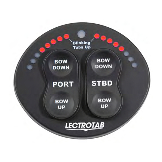
display will show one tab position LED, on both sides, blinking at the top, to indicate both tabs are up.
3. The top portion of the Left switch is marked Port/Bow Down. Pushing this switch deploys the right tab and its
movement is indicated by the Left set of the red LED's. All LED's lit is down. The other 3 switches operate in
the same manner, for port and starboard, bow up and bow down. These switches can be pushed individually,
simultaneously or cross controlled, as appropriate.
4. The spot at the top center is an automatic dimmer for the tab position LED's, for nighttime operations.
5. At trip's end, when the switch which turned the "Oval" on, is turned off, the "Oval" will again initiate a 10 second
calibration sequence to synchronize the tabs and indicators at full retract, and the "Oval" will revert to inoperative
standby, with a 20 ma current draw.
6. If the "Oval" does not appear to be operating correctly, refer to the installation guide on the reverse side for
installation insight, or call 888-LECTROTab for assistance.
7. When leaving the boat, turn off the boat's main D.C. service to turn the 20 ma standby current off.
LECTROTAB ● Linear Devices Corporation ● 11126 Air Park Rd., Suite G ● Ashland, VA 23005 Phone: 804-368-8428, Fax: 804-368-8438,
MODEL SETR-61
www.lectrotab.com
1
Lit # J1107
Revised January 2014
Advertisement

Subscribe to Our Youtube Channel
Related Manuals for Lectrotab Oval SETR-61


Summary of Contents for Lectrotab Oval SETR-61
- Page 1 7. When leaving the boat, turn off the boat’s main D.C. service to turn the 20 ma standby current off. LECTROTAB ● Linear Devices Corporation ● 11126 Air Park Rd., Suite G ● Ashland, VA 23005 Phone: 804-368-8428, Fax: 804-368-8438, www.lectrotab.com...
- Page 2 2. Wire the “Oval” as noted above. If the actuator wires will not reach the control, extend them with AWG # 14 wire. Lectrotab extending cable is color coded black, red, green and white, with recommended connections as follows, BLACK - port actuator black. RED - port actuator white. GREEN - starboard actuator black. WHITE - starboard actuator white.
-
Page 3: Trim Tab Control
* The actual size is about 4” wide, 3 ½” high and ½” deep. Introduction Thanks for your interest in the Lectrotab model SETR-61, Sealed Electronic Trim and Retract system, with tab position indication. The SETR-61 “Oval” is either a stand alone or multi-station, software driven, microprocessor based control, featuring positive click switches with integrated LED position indicators, in a single waterproof unit. - Page 4 The “Oval” Description The SETR-Model SETR-61 “Oval” control operates as described below: Two tab position indicators display left and right tab positions on two separate sets of LEDs. One Blinking LED at the top indicates the tab on the other side is fully retracted as indicated by “Blinking Tabs Up” printed on the face of the control. Photocell senses light level to automatically dim the trim indicator LEDs as daylight fades.
- Page 5 With the Oval, no interface module is used. See the mechanical portion of the Lectrotab installation manual through page 7. Instead of wiring to the manual switches as shown, connect directly to the back of the Oval using ¼”...
- Page 6 After the initial “Oval” has been installed and tested, up to 5 more “Ovals” may be installed as remote stations. For each Oval, one Lectrotab communication wire assembly, part # SR, will be needed. This is an 18 gauge two conductor wire, blue and brown, with a special plug on one end which plugs into the Oval’s communication port on the back side of the control, to the right of Terminal 5.
- Page 7 Alternative Wiring and Operation Per the industry standard, set by most U.S. trim tab manufacturers some years ago, the Lectrotab control switches are set up to be pushed directly according to what the helmsman needs the boat to do. If the bow is high, push the upper portion of both switches to make the bow go DOWN.
- Page 8 The installation and the wiring are quite simple. LECTROTAB ● Linear Devices Corporation ● 11126 Air Park Rd., Suite G ● Ashland, VA 23005 Phone: 804-368-8428, Fax: 804-368-8438, www.lectrotab.com...
- Page 9 Swap LED's: 1 LED on right and left side = LED lights opposite side of key press, 8 LED's on right and left side = LED lights same side as key press LECTROTAB ● Linear Devices Corporation ● 11126 Air Park Rd., Suite G ● Ashland, VA 23005 Phone: 804-368-8428, Fax: 804-368-8438, www.lectrotab.com...
- Page 10 3) The Aux terminal is typically connected to a +12vdc source that is shut down after docking 24vdc. Please call to allow tabs to retract, recalibrate and prevent Lectrotab for fuse damage. sizing (888-532-8768). Lit # J1107 Revised January 2014...
Need help?
Do you have a question about the Oval SETR-61 and is the answer not in the manual?
Questions and answers