Table of Contents

Advertisement

MARINE ELECTRONICS
One Touch To Choose Your World
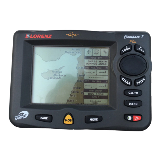
COMPACT 7 Plus
Gray Levels Chartplotter
with Internal GPS Receiver and Antenna
CODE: S3igLZ7m 1001c884/220305
EXCALIBUR 7 Speed
Gray Levels Chartplotter
with External GPS Receiver and Smart Antenna
CODE: S3egLZ7m 1001c884/220305
COMPACT 7 Sun Color
Sunlight Readable Display Color Chartplotter with Internal GPS Receiver and Antenna
CODE: S3igLZ7c 1001c844/220305
EXCALIBUR 7 Speed Sun Color
Sunlight Readable Display Color Chartplotterwith External GPS Receiver and Smart Antenna
CODE: S3egLZ7c 1001c844/220305
U
M
SER
ANUAL
Copyright 2005 LORENZ ELECTRONICS Italia.
All rights reserved. Printed in Italy. No part of this publication may be reproduced or distributed in any form or by any
means, or stored in a database or retrieval system, without prior written permission of the publisher.

Advertisement

Table of Contents
loading

Summary of Contents for Lorenz Excalibur 7 Speed

  • Page 1 CODE: S3egLZ7m 1001c884/220305 COMPACT 7 Sun Color Sunlight Readable Display Color Chartplotter with Internal GPS Receiver and Antenna CODE: S3igLZ7c 1001c844/220305 EXCALIBUR 7 Speed Sun Color Sunlight Readable Display Color Chartplotterwith External GPS Receiver and Smart Antenna CODE: S3egLZ7c 1001c844/220305 ANUAL Copyright 2005 LORENZ ELECTRONICS Italia.
  • Page 2 Warning! Electronic charts displayed by the chartplotter are believed to be accurate and reliable, but they are not intended to replace official charts which should remain your main reference for all the matters related to the execution of a safe navigation. For this reason we would like to remind you that you are required to carry on board and use the officially published and approved nautical charts.
  • Page 3: Table Of Contents

    Table of Content 1 Introduction ................... 11 1.1 CONVENTIONS ..................11 1.2 FEATURES ................... 12 1.2.1 Specifications ................. 12 1.2.1.1 Main Characteristics ............12 1.2.1.2 Phisical Characteristics ............14 1.3 BASICS ................... 15 2 Before You Begin ................... 17 2.1 THE KEYBOARD ..................17 2.2 TURNING THE CHARTPLOTTER ON AND OFF ........
  • Page 4 3.2.7 Nav Aids Presentation ..............32 3.2.8 Input/Output Menu ................32 3.2.8.1 Port 1/Port 2/Port 3 Input ........... 32 3.2.8.2 Port 1/Port 2/Port 3 Output ..........33 3.2.8.3 Port 1/Port 2/Port 3 NMEA Output Messages Selection ... 33 3.2.8.4 GPS Setup Menu ............... 33 Internal GPS F ..
  • Page 5 3.6 MAN OVERBOARD (MOB) ..............50 3.6.1 Inserting MOB .................. 50 3.6.2 Deleting MOB .................. 51 4 For the Experienced User ................... 53 4.1 MORE ABOUT CREATING AND USING ROUTES ........ 53 4.1.1 Waypoint ..................53 4.1.1.1 Adding Waypoint ............... 53 4.1.1.2 Creating a route ..............
  • Page 6 4.3.1 Inserting the A-B-C-D points ............67 4.3.2 Deleting the A-B-C-D Points ............68 4.3.3 Deleting the A-B-C-D Segment ............68 4.3.4 Moving the A-B-C-D points ............. 68 4.3.5 Inserting the A-B-C-D points ............68 4.3.6 Navigating on the A-B-C-D points ..........68 4.4 USING THE TRACK FUNCTIONS ............
  • Page 7 5.2 FIX ................... 80 5.2.1 Fix Correction ................... 81 5.2.2 Compute Correction ................ 81 5.2.3 Correction Offset ................81 5.2.4 Position Filter ................... 81 5.2.5 Speed Filter ..................81 5.2.6 Filter Dump ..................81 5.2.7 Dead Reckoning ................82 5.2.8 Static Navigation ................82 5.3 NAVIGATE ...................
  • Page 8 6.6.3 Cartridges ..................98 6.6.4 Serial Ports ..................99 6.6.5 Modem Test ..................99 A Terms ..................101 B Smart DGPS WAAS Receiver ..................107 B.1 TECHNICAL SPECIFICATIONS ............107 B.1.1 Pysical Characteristics ..............107 B.1.2 Electrical Characteristics .............. 107 B.1.3 GPS Performance ................
  • Page 9: Introduction

    Introduction Congratulations on your purchase of the chartplotter! If you have not used a position-finding instrument before and intend to use your chartplotter for navigating, we suggest you should read this User Manual and make sure you are familiar with its contents. The User Manual is divided into three main parts.
  • Page 10: Features

    1.2 FEATURES The chartplotter is a computer specifically designed for nautical use but, more precisely, to ease and speed up all calculations, which so far have been done manu- ally. If connected to a positioning instrument, the chartplotter displays the current position, the speed, and the heading of the boat and its Track.
  • Page 11 Step by Time : 1, 5, 10, 30 Sec, 1, 5, 10 Min • Cartographic Functions Detailed Map by using C-MAP C-CARD • Coordinates System (ddd mm ss, ddd mm.mm, ddd mm.mmm, UTM, OSGB, TD) • Map Datum • Display Mode (Full, Simple, Fishing, Low, Custom) •...
  • Page 12: Phisical Characteristics

    A-B-C-D Function • Report Functions Depth window • GPS Data page • Navigation Data page • Grafic Data page • Depth Graph page (1/2 screen and 1/3 screen) • About page • Special Functions C-Link, C-Meteo and C-Staff • Fish Finder capability if connected to Fish Finder Black Box •...
  • Page 13: Basics

    Color: Sun Light Viewable LCD (active area 5.6") • Resolution: 320 x 240 pixels • Power consumption Gray Levels: 5 Watt, 10–35 Volt DC • Color: 7.5 Watt, 10–35 Volt DC • Operating Temperature Range From 0°C to 55°C (from 32°F to 131°F) •...
  • Page 14 User Manual...
  • Page 15: Before You Begin

    Before You Begin This chapter provides basic information to get you start using the chartplotter; it will help you to become familiar with the chart display and the functions of the controls before you start using the chartplotter. 2.1 THE KEYBOARD 'CONTRAST'/'BACKLIGHT'/'POWER' key Press and hold the right side of 'POWER' for 1 second to turn the chartplotter On.
  • Page 16: Turning The Chartplotter On And Off

    Press 'MOB' to set MOB (Man OverBoard). When MOB is activated, press 'MOB' to delete it. Press 'CLEAR' to exit from menu or to leave a menu without making changes. In Basic Mode deletes the A, B, C, D points, the User Point (Mark, Event, Waypoint), the MOB, the Target identified by the cursor.
  • Page 17: Turning Off

    emits one rapid beep sound and a title page is opened. After a few seconds, the first of the two Caution Notice pages is displayed, reminding you that the chart plotter is only an aid to navigation, and should be used with appropriate prudence.
  • Page 18: External Connections

    2.5 EXTERNAL CONNECTIONS 2.5.1 GPS CONNECTION FOR CHARTPLOTTER WITH EXTERNAL GPS RECEIVER Connect the GPS to the Port 3: see the picture in Fig. 2.5.1. Control the input setting following the procedure: 'MENU' + "BASIC SETTINGS" + 'ENTER' + "INPUT/OUTPUT" + 'ENTER' + "PORT 3 INPUT"...
  • Page 19 Fig. 2.5.1 - GPS Connection on Port 3 User Manual...
  • Page 20: Autopilot Connection

    2.5.2 AUTOPILOT CONNECTION To connect the Autopilot to the Port 2 see the following picture: Fig. 2.5.2a - Autopilot Connections on Port 2 To choose your preferred setting follow the procedure: 'MENU' + "BASIC SETTINGS" + 'ENTER' + "INPUT/OUTPUT" + 'ENTER' + "PORT 2 OUTPUT"...
  • Page 21: C-Com Gsm Plus Connection

    To choose your preferred setting follow the procedure: 'MENU' + "BASIC SETTINGS" + 'ENTER' + "INPUT/OUTPUT" + 'ENTER' + "PORT 1 INPUT" + 'ENTER' Then choose your preferred setting among the NMEA available settings NMEA 1200-N81-N, NMEA 4800-N81-N, NMEA 4800-N82-N, NMEA 9600-O81- N, NMEA 9600-N81-N (the default setting is 4800-N81-N) and press 'ENTER' to confirm.
  • Page 22: Beacon Receiver Connection

    3. Set the C-COM for Port 1 as follows: 'MENU' + "BASIC SETTINGS" + 'ENTER' + "INPUT/OUTPUT" + 'ENTER' + "PORT 1 INPUT" + 'ENTER' + "C-COM" + 'ENTER' The C-COM can be connected also to the Port 2 and 3, in this case select the format on the used port.
  • Page 23: Inserting C-Card

    or a data storage cartridge. A chart cartridge, called C-CARD, contains detailed charts of the area covered. A data storage cartridge, called User C-CARD can be used to permanently store your routes, Waypoints, Marks, Events and tracks. Note During normal operations the C-CARD should not be removed since the chart plotter may lock 2.6.1 INSERTING C-CARD Hold the C-CARD by the short inclined side so that you can see the C-MAP label.
  • Page 24: Menu Options

    Fig. 2.6.2 - Removing C-CARD Note C-MAP is continuously creating new charts and revising old ones. If you wish to receive information on the newest availbale charts, you can write for the catalog of available C-MAP C-CARD at your dealer. 2.7 MENU OPTIONS You may select how the chartplotter displays primary information (such as how time is displayed) from the main Menu.
  • Page 25: For The New User

    For the New User In order to get started using your chartplotter, you must do the following things: 1) Your chartplotter must have been installed properly according to the in- stallation instruction on Par. 6.2. 2) You must have performed the proper settings for use with your position- ing instrument (see Par.
  • Page 26 Fig. 3.1.1 - Charts and text area The second is with text area on the bottom line of the screen (with partial information on SOG): Fig. 3.1.1a - Charts and text windows If Target is set, in the previous Fig. 3.1.1a instead of the only SOG information window, a text line with DST, BRG, XTE, SOG and TTG information appears.
  • Page 27: Depth Graph

    3.1.2 DEPTH GRAPH The Depth graph can be shown in two different modes. Depth graph dis- played only on 1/3 of the screen: Fig. 3.1.2 - The Depth Graph 1/3 of the screen or Depth graph displayed on 1/2 of the screen: Fig.
  • Page 28: Navigation Data Page

    On the right side of the screen (see Fig. 3.1.3), there is a polar representation of the azimuth and elevation of each satellites. The circle contains a number indicating the PRN of the satellite and it is filled when it is used for the fix solution. On the left side there are histograms indicating the S/N ratio (SNR).
  • Page 29: Basic Settings

    3.2 BASIC SETTINGS The Basic Settings Menu provides access to the set up functions. Here you can choose the language you want (see Par. 2.4). 'MENU' + "BASIC SETTINGS" + 'ENTER' 3.2.1 COURSE VECTOR Disables (Off) or sets time as : 2, 10, 30 min, 1, 2 hours, Infinite. The default setting is Infinite.
  • Page 30: Units Selection

    3.2.6 UNITS SELECTION Allows to select the preferred unit for Distance, Speed, Depth and Altitude (altitude of GPS Antenna on the medium sea level). Speed: Kts(knots)/Mph(miles per hour)/Kph(chilometres per hour). The default set- ting is Kts. 'MENU' + "BASIC SETTINGS" + 'ENTER' + "SPEED" + 'ENTER' Distance: Nm(Nautical Miles)/Sm(statute miles)/Km(chilometres).
  • Page 31: Port 1/Port 2/Port 3 Output

    'MENU' + "BASIC SETTINGS" + 'ENTER' + "INPUT/OUTPUT" + 'ENTER' + "PORT 2 INPUT" + 'ENTER'+ "NMEA-0183 4800-N81-N" + 'ENTER' Note The option C-COM defines on which Port (both Input and Output) the C-COM modem is connected. It is important to remark that this setting affects the Input and the Output of the selected Port. C-COM can only be set on one Port at time.
  • Page 32: Differential Correction Source

    Differential Correction Source Allows setting what kind of Differential Correction will be used by the GPS be- tween WAAS-EGNOS and RTCM (beacon correction). The default setting is WAAS- EGNOS. 'MENU' + "BASIC SETTINGS" + 'ENTER' + "INPUT/OUTPUT" + 'ENTER' + "GPS SETUP"...
  • Page 33: Echosounder

    to the selected time, in the previous example every two minutes. 'MENU' + "BASIC SETTINGS" + 'ENTER' +"C- VOICE" + 'ENTER' + "NAVIGA- TION" + 'ENTER' 3.2.9.2 Echosounder Enables (On) or disables (Off) the Echosounder Voice mode. If it is On, the Depth message is spoken.
  • Page 34: Deleting The A-B-C-D Points

    3.3.2 DELETING THE A-B-C-D POINTS Place the cursor on the desired point (A, B, C or D) and press 'CLEAR': the point is deleted. When the point is deleted, the cursor is placed on the previous point, if existed. The labels of the next points are renamed. 3.3.3 NAVIGATING ON THE A-B-C-D POINTS If fix received is good, place the cursor on the desired point A, B, C or D and press 'GO-TO'.
  • Page 35: Deleting Target

    'PAGE' more times Note If SOG value is less than 1.0 knots or the BRG is greater than 90 degrees, the TTg value is not displayed. 3.4.3 DELETING TARGET Press cursor on Target icon, press 'CLEAR': the symbol identifies Target disappears from the screen.
  • Page 36: Map Menu

    - Perspective View ("Real World" perspective view of the chart, updated realtime during navigation) MAX and NT/NT C-CARD coexistence - When NT data and MAX data cover different areas, the chart plotter gets data from both charts (depending on the current position). - When NT data and MAX data cover the same area, the chart plotter gets data only from MAX chart.
  • Page 37: Map Orientation

    this mode is set the maps are displayed in order to use colors as similar as possible to the ones used in the original paper charts. Classic uses more vivid colors. Night Vision is recommended when the environment is dark in order to reduce the glare of the display.
  • Page 38: Dynamic Nav-Aids

    Fig. 3.5.1.5 - Example of Normal size (on the left side) and Large side (on the right side) settings 3.5.1.6 Dynamic Nav-Aids 'MENU' + "MAP SETTINGS" +'ENTER' + "Dynamic Nav-Aids" + 'ENTER' This function allows settings blinking lights on Nav-Aids. The blink period and color of each Nav-aid is read from the Nav-Aid attributes available on the data cartridge.
  • Page 39: Currents Prediction

    Fig. 3.5.1.8 - Safety Status Bar Boxes definition is as follows: Zoom - Normal: when the chart is displayed at normal scale. - U. Zoom: red when the chart is under-zoomed out more than twice nor- mal scale, gray otherwise. - O.
  • Page 40: Other Map Configurations

    3.5.1.10 Other Map Configurations 'MENU' + "MAP SETTINGS" +'ENTER' + "Other Map Configurations" + 'ENTER' This function allows the user to customize the following selections and is divided into the following setting: Marine Settings, Depth Settings, Land Settings and Chart Settings. Display Mode: To simplify the customization of the chart display, the map settings are now re-organized in modes allowing the user to choose the preferred setting.
  • Page 41 Fig. 3.5.1.10 - Buoy Name On the left side of the previous figure the two buoys have their name shown on the right side. On the right side of the previous figure, the two buoys do not show the name. 'MENU' + "MAP SETTINGS"...
  • Page 42 Tracks & Routes: On/Off. The default setting is On. 'MENU' + "MAP SETTINGS" +'ENTER' + "Other Map Configurations" + 'ENTER' + "Tracks & Routes" + 'ENTER' Underwater Objects: On/Off. The default setting is On. 'MENU' + "MAP SETTINGS" +'ENTER' + "Other Map Configurations" + 'ENTER' + "Underwater Objects"...
  • Page 43: Getting Automatic Info

    Chart Boundaries: On/Off/Auto. The default setting is On. 'MENU' + "MAP SETTINGS" +'ENTER' + "Other Map Configurations" + 'ENTER' + "Chart Boundaries" + 'ENTER' Value Added Data: On/Off. The default setting is On. 'MENU' + "MAP SETTINGS" +'ENTER' + "Other Map Configurations" + 'ENTER' + "Value Added data"...
  • Page 44: Info On Objects With Pictures

    3.5.2.1 Info on objects with Pictures On the Quick Info, there will be the camera icon on the top bar of the window if at least one of the objects found has one or more pictures associated. Fig. 3.5.2.1 - Example of Quick Info on objects with picture On the Full Info, there will be the small camera icon on a corner of the square containing the object icon or a big photo icon centered on the square for the object without icon.
  • Page 45: Info Function

    3.5.4 INFO FUNCTION Place the cursor in any place you want and press: 'MENU' + "INFO" + 'ENTER' to show the Info Tree and Expanded Info page (see Par. 3.5.4). 3.5.5 GETTING PORT INFO Upon viewing the chart of a port or harbour, you will see a Port Info icon that can be clicked on to query the available information immediately displayed with many details.
  • Page 46 Fig. 3.5.6 - Tide Info icon Place the cursor on the Tide symbol, a Automatic Info window is opened: Fig. 3.5.6a - Automatic Info on Tide To display the Tide Graph page, press 'ENTER' for two times. Fig. 3.5.6b - Tide Graph Using the cursor key, it is possible to move the cursor anywhere on the graph and display the time, height (vertical cursor) and draught (horizontal cursor) on a particular graph point.
  • Page 47: Find Function

    Note Tide graphs are an approximation of the Tide and they should be used in conjunction with traditional Tide tables and navigational methods. 3.5.7 FIND FUNCTION The chartplotter allows finding Nearest Services, Port By name, Tide Sta- tions, Wrecks and Obstructions. 3.5.7.1 Finding Nearest Services To locate and display the nearest available facilities of a particular type (i.e.
  • Page 48: Finding Tide Stations

    Allows to locate the port into a selected range. Using the cursor key to insert the preferred value. Press 'ENTER' to confirm. 3.5.7.3 Finding Tide Stations Finds the nearest Tide Stations (up to 10) on the map, from the boat position - if a valid fix is received - or from the cursor position - if the received fix position is not good.
  • Page 49: Deleting Mob

    Fig. 3.6.1 - Man Overboard Note In the information window the bottom side "ENTER for Options" appears only if the "Advanced Functions" item in the "Basic Settings" menu is activated (On), see Par. 3.2.4. 3.6.2 DELETING MOB Press 'MOB', select 'CANCEL" and press 'ENTER' again. The MOB sym- bol remains on the screen shaded until the next screen redraws.
  • Page 50 User Manual...
  • Page 51: For The Experienced User

    For the Experienced User Now you have had a chance to became familiar with your new chartplotter, there are a great number of advanced features that you will find helpful. First of all the use of the Advanced Mode. The chartplotter can operate in two different modes: Basic Mode and Ad- vanced Mode.
  • Page 52: Creating A Route

    Fig. 4.1.1.1 - Waypoint placing 4.1.1.2 Creating a route Repeat the "Adding Waypoint" procedure described in the previous Par. 4.1.1.1. The sequence of moving the cursor and pressing 'ENTER' is continued to create the route, until you have reached the last Waypoint, your final destination. Segments connecting the Waypoints are shown, and the starting point is identified by a circle surrounding the first Waypoint of the route: Fig.
  • Page 53: Deleting Route

    Press 'ENTER'. Select "DELETE" and press 'ENTER'. The Waypoint is deleted and a new line between previous and next Waypoint is shown. The deleted Waypoint remains shaded until the screen is redrawn. Fig. 4.1.1.3a - Deleting Waypoint (II) 4.1.1.4 Deleting route Select Advanced Mode + Place cursor on Waypoint Press 'ENTER'.
  • Page 54: Time To Go

    Time To Go When the Target is set the TTG value is displayed in the Graphic Data page (or in the Navigation Data page): 'PAGE' more times Note If SOG value is less than 1.0 knots or the BRG is greater than 90 degrees, the TTg value is not displayed.
  • Page 55: Inserting Waypoint

    To place the Waypoint in the new position, choose the new place and press 'ENTER' ('CLEAR' otherwise), Waypoint appears in the new position: Fig. 4.1.1.6a - Moving Waypoint function (II) 4.1.1.7 Inserting Waypoint Every time you place the cursor on the segment connecting two existing Waypoints of a route the following function is available.
  • Page 56: Editing Waypoint

    Fig. 4.1.1.7a - Placing Waypoint between two existing ones (II) Once you have positioned the cursor at new location, press 'ENTER' (press 'CLEAR' to abort operation): Fig. 4.1.1.7b - Placing Waypoint between two existing ones (III) 4.1.1.8 Editing Waypoint Select Advanced Mode + Place cursor on Waypoint Press 'ENTER'.
  • Page 57: Finding Info About Waypoints: User Points List Page

    'ENTER': use the cursor key to insert the character (8 characters max), then press 'ENTER'. If Symbol field is selected press 'ENTER': a window with 16 different symbols appears: Fig. 4.1.1.8a - Edit Waypoint (II): Waypoint symbols Use the cursor key to select the symbol and press 'ENTER'. If select Coordinates field, press 'ENTER' and then use the cursor key to insert the value.
  • Page 58: Deleting Selected User Point

    Deleting selected User Point 'MENU' + "ADVANCED SETTINGS" + 'ENTER' + "USER POINTS" + 'ENTER' + "CLR-ONE' + 'ENTER' Deletes the selected User Point. A warning message appears, select "YES" and press 'ENTER' ('CLEAR' otherwise). Deleting all User Points with the same symbol 'MENU' + "ADVANCED SETTINGS"...
  • Page 59: Deleting Route

    A window appears with the route number list and the related route name. Use the cursor key to scroll the list up/down. Pressing 'ENTER' the selected route becames the current route. Note If there is the Target in the current route, it is not possible to change the current route. So if the "Current Route"...
  • Page 60: Selecting Route

    Selecting route 'MENU' + "ADVANCED SETTINGS" + 'ENTER' + "ROUTE" + 'ENTER' + "ROUTE REPORT" + 'ENTER' + "ROUTE #" + 'ENTER' Use the cursor key to select the route number and press 'ENTER'. The route, shown by straight segments, is centered on the screen, with the cursor on the central Waypoint.
  • Page 61: Using Marks & Events

    The received route is saved on the Active route, overwriting it. The NMEA WPL & RTE messages are sent to the input port. 4.2 USING MARKS & EVENTS You may place a Mark, as it is called, at your cursor position, while Event is created at your vessel position.
  • Page 62: Editing Mark

    Fig. 4.2.1.4 - Moving Mark function (I) Press 'ENTER': Fig. 4.2.1.4a - Moving Mark function (II) The Mark is placed in the new position, the "old" Mark, remains on the screen shaded until the screen is redrawn. Note If you try to move a Mark that belongs to many routes, the chart plotter emits three beeps and on the screen a Warning message appears.
  • Page 63: Finding Information About Marks: User Points List Page

    Fig. 4.2.1.5 - Edit Mark Use the cursor key to select the field. If you have selected Name field, press 'ENTER': use the cursor key to insert the character (8 characters max), then press 'ENTER'. If Symbol field is selected press 'ENTER': a window with 16 different symbols appears.
  • Page 64: Adding Event

    ber, directly on the ship's position. Move the cursor to exit from Navigate mode; place the cursor on an Event to access the following functions. 4.2.2.1 Adding Event Select Advanced Mode + 'MODE', then 'ENTER' + "EVENT" + 'ENTER' An Event is placed directly on the ship's position. 4.2.2.2 Deleting Event Place cursor on Event...
  • Page 65: Finding Information About Events: User Points List Page

    Note FOR COLOR CHARTPLOTTER If Color field is selected press 'ENTER': a window with 8 different colors appears, use the cursor key to select the desired color and press 'ENTER'. 4.2.2.5 Finding information about Events: User Points List page 'MENU' + "ADVANCED SETTINGS" + 'ENTER' + "USER POINTS" + 'ENTER' A full window is opened showing information about all stored User Points (Marks, Events and Waypoints).
  • Page 66: Deleting The A-B-C-D Points

    4.3.2 DELETING THE A-B-C-D POINTS When placing the cursor on the desired point (A, B, C or D) the information window appears. Press 'ENTER', select "DELETE" and press 'ENTER' again: the point is deleted. When the point is deleted, the cursor is placed on the previous point, if existed.
  • Page 67: Selecting Active Track

    4.4.1 SELECTING ACTIVE TRACK 'MENU' + "ADVANCED SETTINGS" + 'ENTER' + "TRACK" + 'ENTER' + "AC- TIVE TRK" + 'ENTER' Select the number of the active track. The default setting is 1. 4.4.2 ENABLING TRACK STORING 'MENU' + "CONFIGURAZIONI SPECIALI" + 'ENTER' + "TRACCIA" + 'ENTER' + "TRACCIA"...
  • Page 68: Selecting Track Memorizing Type

    (select "No" otherwise). 4.4.7 SELECTING TRACK MEMORIZING TYPE 'MENU' + "ADVANCED SETTINGS" + 'ENTER' + "TRACK" + 'ENTER' + "STEP UNIT" + 'ENTER' Choose Distance (Dist) - the chartplotter can store a fix when the distance from its last stored position is greater than a defined distance; Time - the chartplotter can store a fix after a defined time;...
  • Page 69: Saving File

    Fig. 4.5 -User C-CARD Menu 4.5.1 SAVING FILE 'MENU' + "ADVANCED SETTINGS" + 'ENTER' + "USER C-CARD" + 'ENTER' + "SAVE" + 'ENTER' A window is opened to insert the file name and the type of data to save: Fig. 4.5.1 - Save File function (I) Select the file name.
  • Page 70: Loading File

    Fig. 4.5.1a - Save File function (II) 4.5.2 LOADING FILE 'MENU' + "ADVANCED SETTINGS" + 'ENTER' + "USER C-CARD" + 'ENTER' + "LOAD" + 'ENTER' Before pressing 'ENTER', choose file name in the list shown on the screen using the cursor key. 4.5.3 DELETING FILE 'MENU' + "ADVANCED SETTINGS"...
  • Page 71: C-Link

    4.6 C-LINK C-Link system is a feature which allows to sharing the same cartographic data between two chart plotter units (CP) linked via serial I/O port. In order to activate C-Link function, a “MAX data C-CARD” (called REGU- LAR C-CARD) must be inserted into one of the two chart plotters and a special MAX data C-CARD (called MIRROR C-CARD) must be inserted on the other chart plotter.
  • Page 72: Operations

    If the Master is navigating to a Route, the Slave will show the Route Leg composed by the Destination and the Waypoint after the Destination (Next Waypoint) and activate the navigation to it. Any variation to the current C-Link navigation data will be transferred from the Master to the Slave.
  • Page 73: C-Link Serial Connection

    Slave chart plotter. Any variation of the C-Link navigation data on the Master will be communicated to the Slave so to keep data aligned on both devices. 4.7.1.2 C-Link serial connection The two chart plotters should be connected via serial ports. Any of the avail- able ports can be used, the software will recognize automatically the serial ports used.
  • Page 74: Inhibit Navigation Operation

    An appropriate warning message will be shown to notify that the Navigation is already active and to confirm whether Slave mode can be set. Inhibit Navigation operation As soon as Slave mode is set, the destination cannot be placed anymore either the C-Link navigation data is received from the Master or not.
  • Page 75: Graphical Representation On Map Display

    4.7.1.6 Graphical representation on Map Display Fig. 4.7.1.6 - Graphical Displaying 4.7.1.7 Route Data Report When the Navigation to the External Route is received, it will be possible to display the information related to the External Route by entering the Route Data Report.
  • Page 76: Quick Info

    - Distance to Next Wpt : Distance to travel from ship to the Wpt after the Des- tination (calculated: Distance to Dest + Next Route Leg length) - Distance to Last Wpt : Distance to travel from ship to the End of the Route (Calculated: Distance to Dest +Distance From Dest to last Wpt received from PCMPN,1) - TTG To Destination...
  • Page 77: Advanced Settings

    Advanced Settings The Advanced Settings menu allows the user to control the advanced func- tions of the chartplotter. The functions are organized into menus. For example all options related to the Fix are in a menu called Fix. For menus there is not an explaniation because they are in the previous Chapters, so for the Map Setting menu see Par.
  • Page 78: Date Format

    5.1.3 DATE FORMAT Sets you preferred date between MM-DD-YY (month-day-year) and DD- MM-YY (day-month-year). The default setting is MM-DD-YY. 'MENU' + "ADVANCED SETTINGS" + 'ENTER' + "SETUP" + 'ENTER' + "DATE FORMAT" + 'ENTER' 5.1.4 WIND SPEED Selects the Wind Speed unit amang Kts = Knots, m/s and Kmh = kilometers per hour.
  • Page 79: Fix Correction

    5.2.1 FIX CORRECTION Turns On/Off the Correction from the positioning system. If the new Cor- rection is calculated, but the Correction is not enabled, the ship's position is not changed. The default setting is Off. 'MENU' + "ADVANCED SETTINGS" + 'ENTER' + "FIX" + 'ENTER' + "FIX COR- RECTION"...
  • Page 80: Dead Reckoning

    'MENU' + "ADVANCED SETTINGS" + 'ENTER' + "FIX" + 'ENTER' + "FILTER DUMP" + 'ENTER' 5.2.7 DEAD RECKONING Enables (On) or disables (Off) the Dead Reckoning. The default setting is Off. 'MENU' + "ADVANCED SETTINGS" + 'ENTER' + "FIX" + 'ENTER' + "DEAD RECKONING"...
  • Page 81: Map Datum

    'MENU' + "ADVANCED SETTINGS" + 'ENTER' + "NAVIGATE" + 'ENTER' + "FIX DATUM" + 'ENTER' 5.3.3 MAP DATUM Selects the Map Datum among 130 items. WGS-84 is the default Fix Datum. 'MENU' + "ADVANCED SETTINGS" + 'ENTER' + "NAVIGATE" + 'ENTER' + "MAP DATUM"...
  • Page 82: Bearings

    5.4.1 BEARINGS Selects either degrees magnetic or true. If magnetic readings are selected the variation is computed automatically for every zone as soon as the chart is displayed. The default setting is Mag. 'MENU' + "ADVANCED SETTINGS" + 'ENTER' + "COMPASS" + 'ENTER' + "BEARINGS"...
  • Page 83: Xte Alarm

    5.5.2 XTE ALARM Disables the XTE Alarm (Off) or selects the desired value. The default setting is Off. 'MENU' + "ADVANCED SETTINGS" + 'ENTER' + "ALARMS" + 'ENTER' + "XTE ALARM" + 'ENTER' 5.5.3 ANCHOR ALARM This function allows inserting of the limit of anchor dragging: beyond that, the alarm is activated.
  • Page 84: Grounding Alarm Range

    5.5.6 GROUNDING ALARM RANGE Allows setting the length of the sector to be detected among 0.25, 0.5, 1.0 Nm. The default setting is 0.25 Nm. When any of the searched objects is found in the scanned area, a tick marker is printed on the relative box in the Grounding Alarm Report page to identify which dangerous objects have been currently detected.
  • Page 85: Date And Time

    'MENU' + "ADVANCED SETTINGS" + 'ENTER' + "SIMULATION" + 'ENTER' + "HEADING" + 'ENTER' 5.6.4 DATE AND TIME 'MENU' + "ADVANCED SETTINGS" + 'ENTER' + "SIMULATION" + 'ENTER' + "DATE" + 'ENTER' 'MENU' + "ADVANCED SETTINGS" + 'ENTER' + "SIMULATION" + 'ENTER' + "TIME"...
  • Page 86: Fish Finder Menu

    5.9 FISH FINDER MENU The chart plotter combined with the sonar performance of the Fish Finder is one of the most advanced marine navigation system available. 'MENU' + "FISH FINDER SETUP" + 'ENTER' For more information see the specific User Manual. User Manual...
  • Page 87: For The Technician

    For the Technician 6.1 DIMENSIONS Fig. 6.1 - EXCALIBUR models Dimensions User Manual...
  • Page 88: Installation And Removing

    Fig. 6.1a - COMPACT models Dimensions 6.2 INSTALLATION AND REMOVING Fig. 6.2 - EXCALIBUR models Installation User Manual...
  • Page 89 Fig. 6.2a - COMPACT models Installation To remove the chartplotter press the bracket button (1) as indicated in the following Fig. 6.2b (left side of the picture for EXCALIBUR models and right side of the picture for COMPACT models) and then eject to the top the chart plotter (2). Fig.
  • Page 90: External Wiring

    6.3 EXTERNAL WIRING Fig. 6.3 - External Wiring for chartplotter with external GPS receiver Fig. 6.3a - External Wiring for chartplotter with internal GPS receiver User Manual...
  • Page 91: Typical Connections

    6.4 TYPICAL CONNECTIONS Fig. 6.4 - Beacon Receive Connection for chartplotter with internal GPS receiver User Manual...
  • Page 92 Fig. 6.4a - GPS Connection on Port 3 for chartplotter with external GPS receiver User Manual...
  • Page 93 Fig. 6.4b - Autopilot Connection on Port 2 Fig. 6.4c - External NMEA Connection on Port 1 Fig. 6.4d - C-COM Connection on Port 1 User Manual...
  • Page 94: Troubleshooting

    6.5 TROUBLESHOOTING The following is a brief guide to some of the problems you may experience while using the chartplotter with common solutions. 6.5.1 PROBLEMS AND SOLUTIONS The chartplotter does not turn On — Make sure that the correct voltage (10-35 volt dc) is present.
  • Page 95: World Background Charts

    have the option of saving user Marks, Track history and Routes to a User C-CARD (this is an optional purchase from your dealer). To perform a RAM Clear see Par. 6.6.1. If you still need assistance, call your local dealer, reporting the Software Re- lease and Cartography information available in the About page.
  • Page 96: Ram Menu

    Use the cursor key to select the preferred test: this will display in reverse video and with the relative menu window. To choice the test press 'ENTER'. To exit from any submenu press 'CLEAR'. To exit from the System Test turn Off the chartplotter.
  • Page 97: Serial Ports

    1. if there is a C-CARD inserted in the slot and there is not a malfunction, the name of the C-CARD zone and the message "OK" are shown. 2. if there is a C-CARD inserted in the slot, but it is a damaged C-CARD, the name of the C-CARD zone and the message "Faulty"...
  • Page 98 User Manual...
  • Page 99: A Terms

    Terms This section explains the terms that may be unfamiliar to the reader. Advanced Mode The chartplotter can operate in two different modes: Basic Mode and Advanced Mode. In Advanced Mode it is possible to have more available functions, for example it is possible to handle Waypoints. Altitude Altitude of GPS Antenna on the medium sea level.
  • Page 100 Chain Selects the preferred chain. The Loran chains are groups of transmitting stations that use timed radio pulse transmissions. In each of these chains there is a master station and two or more slave or secondary stations. Stations belonging to a same chain transmit pulses in timing groups: a different time base identifies each chain.
  • Page 101 HDG = Heading The horizontal direction in which a ship actually points or heads in any moment (see also COG). HDOP = Horizontal Dilution Of Precision It is the index for position-fixing accuracy. The smaller the HDOP value, the more accurately the position can be fixed Home In this operating mode (called also Navigate mode) all operations refer to the ship's position.
  • Page 102 Fig.A.1 - Pictures and Diagrams OSGB = Ordnance Survey of Great Britain A coordinate system describing only Great Britain. Generally used with GBR36 datum, which also describes only Great Britain. This coordinate system cannot be used in any other part of the world. Port Info The Port Info function is a combination of a new Port Info database containing all the relevant Safety and Navigational information normally found in good pilot books and a new presentation software...
  • Page 103 Tide Info The Tide Info feature is the combination of a new tide heights database that will be included within new C-CARDs and new features which calculate the tide graph for all primary and secondary ports world-wide. This function can calculate the tide heights for any past or future date and as a by-product of this calculation will also display the Maximum and Minimum Tide height and time for the day selected plus the times of Sunrise and Sunset.
  • Page 104 UTC = Universal Time Coordinated A time scale based on the rotation of the earth that is used by most broadcast time services. UTM = Universal Transverse Mercator Metric Grid system used on most large and intermediate scale land topographic charts and maps. VAD = Value Added Data The Value Added Data (VAD) is a collection of additional cartographic objects which are not present on the original paper chart (from which the electronic chart derives).
  • Page 105: B Smart Dgps Waas Receiver

    Smart DGPS WAAS Receiver The Smart DGPS WAAS receiver is based on a ultimate 12 channel GPS engine that delivers accuracy better than three meters by decoding the GPS correc- tion signals from the satellite-based WAAS (Wide Area Augmentation System). The GPS engine, interface electronics and the passive antenna are enclosed inside the water-proof plastic housing.
  • Page 106: Environmental Characteristics

    Acquisition Time (Approximate) Hot start : < 20 seconds Warm start : < 45 seconds Cold start : < 40 seconds : RTCM SC104 v. 2,WAAS (North America), EGNOS DGPS Capability (Europe), MSAS (Asia) Output Format : NMEA 0183 Version 2.0, Baud Rate 4800, N81 Interfaces : Asynchronous serial output compatible with RS-232 (TTL...
  • Page 107: Mechanical Characteristics & Mounting

    are defined in "NMEA-0183 Version 2.0" (for more information see NMEA, www..nmea.org). B.4 MECHANICAL CHARACTERISTICS & MOUNTING B.4.1 INSTALLING Choose a location for the antenna that has a clear view of the sky. Ensure there are no major obstructions or fixtures in the immediate proximity to the an- tenna.
  • Page 108: Dimensions

    Fig.B.4.1a - Installing GPS Antenna (II) 3. Remove the template and let the cable go through the central hole. 4. Apply a small coat of RTV to the underside of the antenna. 5. Place the antenna and then screw it with the three M3 screws. Fig.B.5.4.1b - Installing GPS Antenna (III) B.4.2 DIMENSIONS Fig.B.4.2 - GPS Antenna Dimensions...
  • Page 109: Analytical Index

    Analytical Index C-CARD Test ........98 A-B-C-D function ......35, 67 C-COM ..........23 Add to Route ........65, 67 C-COM Connection ......23 Adding Event ........66 C-COM GSM Plus ....... 23 Adding Mark .......... 63 C-Link ..........34, 73 Adding Waypoint ........
  • Page 110 Datum ..........102 Finding User Point ........ 59 Dead Reckoning ........82 Fish Finder ..........88 Default ..........102 Fix Correction ........81 Deleting A-B-C-D ......36, 68 Fix Datum ..........82 Deleting Event ........66 Fix menu ..........80 Deleting File ..........
  • Page 111 Light Sectors ......... 43 POIs ............44 line pattern ..........69 Port 1/Port 2/Port 3 Input ..... 32 Loading File .......... 72 Port 1/Port 2/Port 3 NMEA Output ..33 LOG ............ 103 Port 1/Port 2/Port 3 Output ....33 Longitude ..........
  • Page 112 Spot Sounding ........104 Typical Connection ....... 93 Static Navigation ........82 Steering ..........104 STR ............. 104 Underwater Objects ......44 Structure ..........41 Units Selection ........32 Surface Clutter ........41 User C-CARD ........ 70, 99 System Test .......... 97 User Point ......

This manual is also suitable for:

Compact 7 sun colorCompact 7 plusExcalibur 7 speed sun color

Table of Contents