Advertisement
Quick Links
Download this manual
See also:
Quick Start Manual
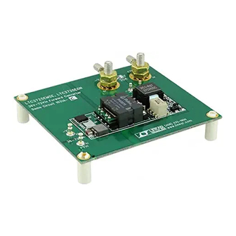
QUICK START GUIDE FOR DEMONSTRATION CIRCUIT 1031A-C
DESCRIPTION
Demonstration circuit 1031A-C is a 36V-72Vin, syn-
chronous
forward
LTC3725/LTC3726. This circuit was designed spe-
cifically to attain a high current, low ripple, synchro-
nously rectified forward to efficiently power 5.0V
loads at up to 20A from a typical telecom input volt-
age range. This circuit features secondary-side con-
Table 1. Performance Summary (T
PARAMETER
Minimum Input Voltage
Maximum Input Voltage
Output Voltage V
OUT
Maximum Output Current
Typical Output Ripple V
OUT
Size
Load Transient Response
Nominal Switching Frequency
Efficiency
OPERATING PRINCIPLES
The LTC3726 controller is used on the secondary and
the LTC3725 driver with self-starting capability is
used on the primary. When an input voltage is ap-
plied, the LTC3725 begins a controlled soft-start of
the output voltage. As this voltage begins to rise, the
LTC3726 secondary controller is quickly powered up
via T1, D1, and Q27. The LTC3726 then assumes
control of the output voltage by sending encoded
PWM gate pulses to the LTC3725 primary driver via
the small signal transformer, T2. The LTC3725 then
operates as a simple driver receiving both input sig-
nals and bias power through T2.
36V-72VIN, SYNCHRONOUS FORWARD CONVERTER
converter
featuring
= 25°C)
A
CONDITION
V
= 36V to 72V, I
IN
200LFM Airflow
V
= 72V, I
IN
Component Area x Top Component Height
Peak Deviation with Load Step of 10A to 20A (10A/us)
Settling Time
V
= 48V, I
IN
trol of the supply eliminating the need for an opto-
the
coupler, self-starting architecture, input undervoltage
lockout, and output overvoltage protection.
Design files for this circuit board are available.
Call the LTC factory.
, LTC and LT are registered trademarks of Linear Technology Corporation.
= 0A to 20A
OUT
= 20A
OUT
= 20A
OUT
The transition from primary to secondary control oc-
curs seamlessly at a fraction of the output voltage.
From that point on, operation and design simplifies to
that of a simple buck converter. Secondary sensing
eliminates delays, tames large-signal overshoot and
reduces output capacitance while utilizing off-the-
shelf magnetics and attaining high efficiency.
For large values of input inductance, a 100V, 47uF elec-
trolytic capacitor can be added across the input termi-
nals to damp the input filter and provide adequate stabil-
ity. See Linear Technology Application Note AN19 for a
discussion on input filter stability analysis. A recom-
mended part is the Sanyo 100MV39AX.
LTC3725 / LTC3726
VALUE
36V
72V
5.0V
20A
100mV
P–P
2.3" x 0.9" x 0.394"
±200mV
40us
300kHz
91.5% Typical
1
Advertisement

Related Manuals for Linear Technology LTC3725


Summary of Contents for Linear Technology LTC3725
- Page 1 5.0V loads at up to 20A from a typical telecom input volt- , LTC and LT are registered trademarks of Linear Technology Corporation. age range. This circuit features secondary-side con- Table 1. Performance Summary (T = 25°C)
-
Page 2: Quick Start Procedure
QUICK START PROCEDURE Demonstration circuit 1031A-C is easy to set up to Turn on the power at the input. evaluate the performance of the LTC3725/LTC3726. Make sure that the input voltage never ex- NOTE: Refer to Figure 1 for proper measurement equipment ceeds 72V. - Page 3 QUICK START GUIDE FOR DEMONSTRATION CIRCUIT 1031A-C 36V-72VIN, SYNCHRONOUS FORWARD CONVERTER Figure 1. Proper Measurement Equipment Setup Figure 2. Measuring Input or Output Ripple...
-
Page 4: Measured Data
QUICK START GUIDE FOR DEMONSTRATION CIRCUIT 1031A-C 36V-72VIN, SYNCHRONOUS FORWARD CONVERTER MEASURED DATA Figures 3 through 11 are measured data for a typical DC1031A-C. Figures 12 through 21 are schematics, bill of mate- rials and layout. LOAD CURRENT (A) Figure 3. Efficiency (200lfm airflow) 50mV/div 1us/div Figure 4. - Page 5 QUICK START GUIDE FOR DEMONSTRATION CIRCUIT 1031A-C 36V-72VIN, SYNCHRONOUS FORWARD CONVERTER Vout 200mV/DIV Iout 10A/div 20us/DIV Figure 5. Output Voltage Transient Response (48Vin, 10A to 20A step)
- Page 6 QUICK START GUIDE FOR DEMONSTRATION CIRCUIT 1031A-C 36V-72VIN, SYNCHRONOUS FORWARD CONVERTER Figure 6. Temp Data (48Vin, 20A, 25 C, 200LFM airflow – front) Figure 7. Temp Data (48Vin, 20A, 25 C, 200LFM airflow – back) Figure 8. Temp Data (36Vin, 20A, 25 C, 200LFM airflow – front)
- Page 7 QUICK START GUIDE FOR DEMONSTRATION CIRCUIT 1031A-C 36V-72VIN, SYNCHRONOUS FORWARD CONVERTER Figure 9. Temp Data (36Vin, 20A, 25 C, 200LFM airflow – back Figure 10. Temp Data (72Vin, 20A, 25 C, 200LFM airflow – front) Figure 11. Temp Data (72Vin, 20A, 25 C, 200LFM airflow – back)
- Page 8 QUICK START GUIDE FOR DEMONSTRATION CIRCUIT 1031A-C 36V-72VIN, SYNCHRONOUS FORWARD CONVERTER Figure 12. Simplified Schematic...
- Page 9 QUICK START GUIDE FOR DEMONSTRATION CIRCUIT 1031A-C 36V-72VIN, SYNCHRONOUS FORWARD CONVERTER Figure 13. Full Board Schematic...
- Page 10 QUICK START GUIDE FOR DEMONSTRATION CIRCUIT 1031A-C 36V-72VIN, SYNCHRONOUS FORWARD CONVERTER Item Reference Part Description Manufacture / Part # REQUIRED CIRCUIT COMPONENTS C2,C3,C4,C5 CAP., X7R, 1.0uF, 100V, 20%, 1210 TDK, C3225X7R2A105M C71,C24 CAP., X7R, 1uF, 16V 10%, 0805 TAIYO YUDEN, EMK212BJ105KG C27,C70 CAP., X7R, 330pF, 25V, 10%, 0603 AVX, 06033C331KAT2A...
- Page 11 QUICK START GUIDE FOR DEMONSTRATION CIRCUIT 1031A-C 36V-72VIN, SYNCHRONOUS FORWARD CONVERTER RES., CHIP, 536, 1/16W, 5%, 0603 AAC, CR16-5360FM TRANSFORMER, 1750VDC BASIC, PA0811 PULSE, PA0811 TRANSFORMER, 1500VRMS BASIC, PA0297 PULSE, PA0297 I.C., LTC3725EMSE, MS10E LINEAR TECH., LTC3725EMSE I.C., LTC3726EGN, SSOP16GN LINEAR TECH., LTC3726EGN ADDITIONAL DEMO BOARD CIRCUIT COMPONENTS C23,C76 (opt.)
- Page 12 QUICK START GUIDE FOR DEMONSTRATION CIRCUIT 1031A-C 36V-72VIN, SYNCHRONOUS FORWARD CONVERTER Figure 15. Top...
- Page 13 QUICK START GUIDE FOR DEMONSTRATION CIRCUIT 1031A-C 36V-72VIN, SYNCHRONOUS FORWARD CONVERTER Figure 16. Layer 2...
- Page 14 QUICK START GUIDE FOR DEMONSTRATION CIRCUIT 1031A-C 36V-72VIN, SYNCHRONOUS FORWARD CONVERTER Figure 17. Layer 3...
- Page 15 QUICK START GUIDE FOR DEMONSTRATION CIRCUIT 1031A-C 36V-72VIN, SYNCHRONOUS FORWARD CONVERTER Figure 18. Layer 4...
- Page 16 QUICK START GUIDE FOR DEMONSTRATION CIRCUIT 1031A-C 36V-72VIN, SYNCHRONOUS FORWARD CONVERTER Figure 19. Layer 5...
- Page 17 QUICK START GUIDE FOR DEMONSTRATION CIRCUIT 1031A-C 36V-72VIN, SYNCHRONOUS FORWARD CONVERTER Figure 20. Bottom...
- Page 18 QUICK START GUIDE FOR DEMONSTRATION CIRCUIT 1031A-C 36V-72VIN, SYNCHRONOUS FORWARD CONVERTER Figure 21. Bottom Mirrored...
- Page 19 Mouser Electronics Authorized Distributor Click to View Pricing, Inventory, Delivery & Lifecycle Information: Analog Devices Inc. DC1031A-C...
Need help?
Do you have a question about the LTC3725 and is the answer not in the manual?
Questions and answers